Table of Contents
Advertisement
Quick Links
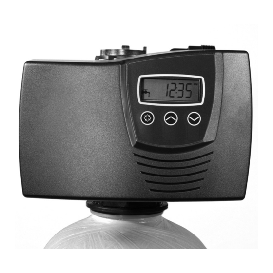
Fleck 7000SXT
Service Manual
TABLE OF CONTENTS
JOB SPECIFICATION SHEET . ..............................................1
INSTALLATION ......................................................................2
START-UP INSTRUCTIONS . .................................................2
TIMER FEATURES ................................................................3
TIMER OPERATION ..............................................................4
MASTER PROGRAMMING MODE CHART ..........................5
MASTER PROGRAMMING MODE . .......................................6
USER PROGRAMMING MODE . ............................................9
DIAGNOSTIC PROGRAMMING MODE . ...............................10
POWERHEAD A SSEMBLY . ...................................................11
VALVE A SSEMBLY .................................................................12
BYPASS A SSEMBLY..............................................................13
BYPASS VALVE A SSEMBLY (PLASTIC) . ..............................14
TROUBLESHOOTING . ..........................................................15
REMOVING GEAR BOX A SSEMBLY . ...................................17
INSERTING CIRCUIT BOARD ...............................................17
CONNECTING THE CIRCUIT BOARD . .................................17
WATER CONDITIONER FLOW DIAGRAMS . ........................18
INJECTOR FLOW DATA . .......................................................19
METER FLOW DATA . .............................................................20
DIMENSIONS . ........................................................................20
JOB SPECIFICATION SHEET
Job Number: ___________________________________________________
Model Number: _________________________________________________
Water Hardness: _ ______________________________________ ppm or gpg
Capacity Per Unit: _______________________________________________
Mineral Tank Size: _ _____________ Diameter: ________ Height: _________
Salt Setting per Regeneration: _____________________________________
1. Type of Timer:
A. 7 Day or 12 Day
B. Meter Initiated
2.
3. Meter Size:
A. 3/4" Std Range (125 - 2,100 gallon setting)
B. 3/4" Ext Range (625 - 10,625 gallon setting)
C. 1" Std Range (310 - 5,270 gallon setting)
D. 1" Ext Range (1,150 - 26,350 gallon setting)
E. 1-1/2" Std Range (625 - 10,625 gallon setting)
F. 1-1/2" Ext Range (3,125 - 53,125 gallon setting)
G. 2" Std Range (1,250 - 21,250 gallon setting)
H. 2" Ext Range (6,250 - 106,250 gallon setting)
I. 3" Std Range (3,750 - 63,750 gallon setting)
J. 3" Ext Range (18,750 - 318,750 gallon setting)
K. Electronic _ ________ Pulse Count ________ Meter Size _______
4. System Type:
A. System #4: 1 Tank, 1 Meter, Immediate, or Delayed Regeneration
B. System #4: Time Clock
C. System #4: Twin Tank
D. System #5: 2-5 Tanks, Interlock Mechanical
2-4 Tanks, Interlock Electronic
Meter per unit for Mechanical and Electronic
E. System #6: 2-5 Tanks, 1 Meter, Series Regeneration, Mechanical
2-4 Tanks, 1 Meter, Series Regeneration, Electronic
F. System #7: 2-5 Tanks, 1 Meter, A lternating Regeneration,
Mechanical
2 Tanks only, 1 Meter, A lternating Regeneration,
Electronic
G. System #9: Electronic Only, 2-4 Tanks, Meter per Valve, A lternating
H. System #14: Electronic Only, 2-4 Tanks, Meter per Valve. Brings
5.
A. Backwash: _ __________________________________ Minutes
B. Brine and Slow Rinse: _ _________________________ Minutes
C. Rapid Rinse: _________________________________ Minutes
D.
______________________________ Minutes
E. Pause Time: _ _________________________________ Minutes
F. Second Backwash: ____________________________ Minutes
6.
______________________________gpm
7. Brine Line Flow Controller: ____________________________gpm
8. Injector Size#: _ ___________________________________________
9. Piston Type:
A. Hard Water Bypass
B. No Hard Water Bypass
42775 Rev D JL10
Advertisement
Table of Contents

Related Manuals for Pentair Fleck7000SXT


Summary of Contents for Pentair Fleck7000SXT
-
Page 1: Table Of Contents
Fleck 7000SXT Service Manual TABLE OF CONTENTS JOB SPECIFICATION SHEET JOB SPECIFICATION SHEET ..........1 Job Number: ___________________________________________________ Model Number: _________________________________________________ INSTALLATION ..............2 Water Hardness: _ ______________________________________ ppm or gpg START-UP INSTRUCTIONS ..........2 Capacity Per Unit: _______________________________________________ TIMER FEATURES ..............3 Mineral Tank Size: ... -
Page 2: Installation
INSTALLATION 11. Slowly place the by-pass in service position and let water A minimum of 20 pounds (1.4 bar) of water pressure is required open a cold water tap nearby and let run until the air is for regeneration valve to operate effectively. -
Page 3: Timer Features
Parameter Data Display Display Indicator 1. Press and hold either the Up or Down buttons until the Error/ Information programming icon replaces the service icon and the Icon parameter display reads DO. 2. Adjust the displayed time with the Up and Down buttons. Flow Indicator 3. -
Page 4: Timer Operation
TIMER OPERATION 1. When timer is in service, press the Extra Cycle button for 5 A meter immediate control measures water usage and seconds on the main screen. regenerates the system as soon as the calculated system 2. -
Page 5: Master Programming Mode Chart
MASTER PROGRAMMING MODE CHART Option Options Gallons Display Format Liters dF2b Softener Double Backwash Fltr Filter Valve Type difff Air Injected Oxidizer Meter Delayed Meter Immediate Control Type Time Clock Day of Week, Time Clock fdpb Flow Delayed Proportional brining Unit Capacity Unit Capacity (Grains) Hardness... -
Page 6: Master Programming Mode
MASTER PROGRAMMING MODE When the Master Programming Mode is entered, all available option setting displays may be viewed and set as needed. Press the Extra Cycle button. Use this display to set the Depending on current option settings, some parameters cannot be viewed or set. - Page 7 MASTER PROGRAMMING MODE continued Press the Extra Cycle button. Use this display to set the Unit Press the Extra Cycle button. Use this display to set the system media. Enter the capacity of the media bed in grains system capacity will be held as a reserve.
- Page 8 MASTER PROGRAMMING MODE continued Press the Extra Cycle button. Use this display to set the Press the Extra Cycle button. Use this display to set the current control will initiate a delayed, manually queued, or day override corner of the screen.
-
Page 9: User Programming Mode
6. Press the Extra Cycle button. Use this display to set the Description “CD” in the upper left hand corner of the screen. Day Override The timer’s day override setting Regeneration The time of day that the system Time will regenerate (meter delayed, ... -
Page 10: Diagnostic Programming Mode
DIAGNOSTIC PROGRAMMING MODE 6. Press the Up button. Use this display to view the Reserve Description upper left hand corner of the screen. Flow Rate Peak Flow Rate rate measured since the last regeneration Hours in Displays the total hours that the unit ... -
Page 11: Powerhead Assembly
POWERHEAD ASSEMBLY BR61501-7000SXT 1 ....1 ..10218 ....Switch, Micro (Optional) 2 ....1 ..40978 ....Support, Upper Bearing 3 ....1 ..61696 ....Circuit Board ... -
Page 12: Valve A Ssembly
* See NOTE 61500-7000EXP Rev C 1 ....1 ..61050 ......Valve Body A ssembly, 7000, 32 mm Dist ... 61455-24 ....DLFC 3/4", 2.4 gpm 2 ....1 ..61452-10 ....Piston A ssembly, 7000, Softener, D/F 35 ... -
Page 13: Bypass Assembly
BYPASS ASSEMBLY 41118 Rev A 41147 Rev A 1 ....1 ..40569 ....Bypass A ssembly, 7000, Less 2 ..61562-10 ...Connector A ssembly, 1-1/2" BSP, Clip 7000, Brass ... -
Page 14: Bypass Valve A Ssembly (Plastic)
1 ....1 ..19645 ....Body, Safety Brine Valve, 2310 2 ....1 ..19803 ....Safety Brine Valve A ssy 3 ....1 ..19804 ....Screw, Sckt Hd, Set, 10-24 x .75 ... -
Page 15: Troubleshooting
Correction Water conditioner fails to Electrical service to unit has been Assure permanent electrical service (check fuse, regenerate. interrupted plug, pull chain, or switch) Timer is defective. Replace timer. Power failure. Reset time of day. Hard water. By-pass valve is open. - Page 16 continued Error Type Cam Sense The valve drive took longer than Unplug the unit and examine the powerhead. Verify that all cam switches are Error 6 minutes to advance to the next connected to the circuit board and functioning properly. Verify that the motor regeneration position and drive train components are in good condition and assembled properly.
-
Page 17: Removing Gear Box A Ssembly
2. When all the way down, snap the circuit board into place under the notches on the right. 40988 REV A Figure 3 1. Unplug the power source. 41033 REV B 2. With 3/8" nut driver, turn the cycle cam counter-clockwise to the position shown in illustration above. -
Page 18: Water Conditioner Flow Diagrams
WATER CONDITIONER FLOW DIAGRAMS Slow Rinse Position 40988 REV A 40988 REV A 41121 REV A 41121 REV A 40988 REV A 41121 REV A 40988 REV A 41121 REV A Brine Position 40988 REV ... -
Page 19: Injector Flow Data
INJECTOR FLOW DATA TR18755 REVB... -
Page 20: Meter Flow Data
METER FLOW DATA TR18753 Softener TR18688 Filter 41140-02 REV A DIMENSIONS 41023 REV C © 2010 Pentair Residential Filtration, LLC 42775 Rev D JL10...