Table of Contents
Advertisement
Quick Links
OWNER'S/OPERATOR'S MANUAL
This manual covers the following filter tanks:
THS3461
THS3484
THS4272
THS4284
THS4296
WARNING: This manual contains critical safety information that must be furnished to the end
user. Failure to read and follow the instructions could result in serious personal injury and/or
major property damage.
PENTAIR POOL PRODUCTS
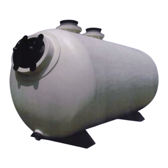
THS SERIES FILTER
TANKS ONLY
Pentair Pool Products
1620 Hawkins Ave.
Sanford, NC 27330
Phone: 919-774-4151
Fax: 919-774-4841
Advertisement
Table of Contents

Related Manuals for Pentair filter


Summary of Contents for Pentair filter
- Page 1 PENTAIR POOL PRODUCTS OWNER’S/OPERATOR’S MANUAL This manual covers the following filter tanks: THS3461 THS3484 THS4272 THS4284 THS4296 WARNING: This manual contains critical safety information that must be furnished to the end user. Failure to read and follow the instructions could result in serious personal injury and/or major property damage.
-
Page 2: Table Of Contents
TABLE OF CONTENTS 1.0 Basic Principles of Operation 1.1 Filtration - How Your Filter Works 1.2 Backwash 2.0 Installation and Assembly 2.1 Receiving and Inspecting 2.2 Locating the Filter 2.3 Setting Anchor Bolts 2.4 Install All Piping 2.5 Inspection of Components 2.6 Pressure Test System... -
Page 3: Basic Principles Of Operation
Thank you for purchasing your new high rate sand filter from Paragon Aquatics. Your new filter vessel is the best that money can buy, with its ability to operate for years with a minimum amount of maintenance, as well as having excellent resistance to corrosion due to its all fiberglass construction. -
Page 4: Backwash
The basic principal of filter backwash is to reverse the flow of water through the filter. This will remove the dirt and debris trapped in the filter bed. For this principal to work properly a flow of 15-20 GPM per square foot of filter area should pass through the filter in the reverse direction. -
Page 5: Installation And Assembly
Dimensions ‘A’ and ‘B’ in Figure 1 (next page) give the minimum filter to wall clearance in order to maintain a 6” minimum clearance between the tank and the wall (or other equipment). These are only given as minimum distance guidelines. -
Page 6: Setting Anchor Bolts
"A" Model (in.) THS3461 THS3484 THS4272 THS4284 THS4296 • Ensure that the tank(s) are level, both across each pipe connection and from the influent pipe to the effluent pipe. For two tank systems, make sure the tanks are level to each other. If adjustments need to be made, loosen the nut underneath the saddles and adjust the saddle placement as needed. -
Page 7: Install All Piping
2.5 Inspection of Components Before performing the initial start up of the filter system, inspect the tanks and components to ensure that no damage has occurred during the shipment of the vessel. -
Page 8: Pressure Test System
All gases are compressible, and under pressure create a danger. Severe bodily injury or property damage could occur if the filter is subjected to air or gas pressure. CAUTION: DO NOT exceed the maximum working pressure of the vessel (50 psi) during testing or operation. -
Page 9: Media Installation
3.0 Start-up and Operation The following steps should be followed in the order shown for initial start up of the filter system. Each section will be explained in more detail in the following pages. 1. Start system in backwash mode 2. -
Page 10: Maintenance
4.1 for more details. Appendix D, which will be referred to later, provides a chart to log these pressures into for future reference. Congratulations, your filter is now ready to filter water. Please read the next section on Maintenance to learn how to care for your new filter tank(s). -
Page 11: Periodic Inspection Of Filters
4.2 Periodic Inspection of filters Part of the maintenance schedule that is suggested for these tanks is to check certain areas of the filter tanks for signs of possible problems. Below are some key areas, which should be inspected regularly. -
Page 12: Draining The Filters
Some maintenance may require the filters to be drained of all water. To accomplish this you must: • Make sure that the system is shut down. Isolate all water sources from the filter(s). • Remove the drain cap located on the bottom of the front of the tank. See figure below for location. -
Page 13: Installation/Removal Of Manway Cover
Snug yoke bolts. Tighten bolts one full turn past hand tight. If manway leaks during refilling of system, tighten bolts in quarter turn increments until leak stops. After filter is at operating pressure, yokes will be loose due to internal pressure. Snug bolts until yokes no longer move. -
Page 14: Winterizing The Filter Tanks
Loosen any flanges in low-lying sections of piping to completely drain the system of water. • Store any plugs/caps removed near the filter and mark all flanges that have been loosened so that they may be reinstalled and tightened at time of start Tank Owner’s Manual 9/26/05 Pg. -
Page 15: Appendix
APPENDIX A APPENDIX B APPENDIX C APPENDIX D APPENDIX E APPENDIX F Tank Owner’s Manual 9/26/05 APPENDIX PRESSURE DIFFERENTIAL CURVES MEDIA REQUIREMENTS TROUBLE SHOOTING BACKWASH LOG GENERAL TANK SPECIFICATIONS TANK PARTS Pg. 15 of 23 Rev. D... - Page 16 Clean Filter Pressure Drop Clean Filter Pressure Drops NOTE: 1. The charts are based on using NSF approved #20 sand in the filters. Variation in sand media may affect pressure differential values. 2. These charts are for pressure drop through the tanks only. Depending on the location of the pressure gauges, there will likely be additional contributors to the pressure differential, such as valves, fittings, etc.
- Page 17 Filter Area Filter Model THS3461 13.5 THS3484 19.0 THS4272 19.7 THS4284 23.2 THS4296 26.7 Media Type Media Size Specific Gravity Pea Gravel 1/4" - 1/8" Greater than 2.5 #20 Standard Sand .018"-.022" (.45mm-.55mm) NOTE: 1. All gravel and sand should be washed and screened. It should contain less than 1% of loam, clay, sand, shells, dirt organic impurities or other foreign matter.
-
Page 18: Appendix
1-6 hours typically depending on the application and appropriate codes. If the filter system is filtering the water too slow, dirt and debris can build up faster than the water is cleaned. The flow through the filters may need to be increased. - Page 19 1. After performing the backwash for the initial start up, and returning the filter to normal operation, record the clean filter influent and effluent pressures into the first line of the chart and calculate ∆ P for a clean filter. It is recommended that backwashing occur when the pressure differential increases by 10 Psi from this value.
- Page 20 APPENDIX E Tank Owner’s Manual Pg. 20 of 23 9/26/05 Rev. D...
- Page 21 SS-THS3461 SPEC SHEET HERE Tank Owner’s Manual Pg. 21 of 23 9/26/05 Rev. D...
- Page 22 SS-THS SPEC SHEET HERE Tank Owner’s Manual Pg. 22 of 23 9/26/05 Rev. D...
- Page 23 Ref # Part Number B4848BL Tank Saddle, Black B4856 Yoke, Dog (Manway) B4852ABL Glass Filled Manway Cover (Black) B4951 HHMB, 3/4" x 4" T316 S/S B4860 3/4" Flat Washer, T316 S/S B4804 B4803 3 1/2" Effluent Lateral B4980 Media Dump Assembly B4981 1 1/2"...