SMA SUNNY BOY 3000-US Installation Manual
Pv inverter
Hide thumbs
Also See for SUNNY BOY 3000-US:
- Installation manual (106 pages) ,
- Installation manual (100 pages) ,
- User manual (36 pages)

Related Manuals for SMA SUNNY BOY 3000-US


Summary of Contents for SMA SUNNY BOY 3000-US
- Page 1 PV Inverter SUNNY BOY 3000-US / 3800-US / 4000-US Installation Manual SB30-40-US-IA-en-33 | TBUS-SB30_40US | Version 3.3...
- Page 3 All such warranties are expressly disclaimed. Neither SMA America, LLC nor its distributors or dealers nor SMA Solar Technology Canada Inc. nor its distributors or dealers shall be liable for any indirect, incidental, or consequential damages under any circumstances.
-
Page 4: Important Safety Instructions
A warning describes a hazard to equipment or personnel. It calls attention to a procedure or practice, which, if not correctly performed or adhered to, could result in damage to or destruction of part or all of the SMA equipment and/or other equipment connected to the SMA equipment or personal injury. Symbol... - Page 5 The product contains no user-serviceable parts. For all repair and maintenance, always return the unit to an authorized SMA Service Center. Before installing or using the product, read all of the instructions, cautions, and warnings in this manual.
- Page 6 General Warnings SMA America, LLC SB30-40-US-IA-en-33 Installation Manual...
-
Page 7: Table Of Contents
SMA America, LLC Table of Contents Table of Contents Information on this Document..... . 11 Safety ......... 13 Intended Use. - Page 8 Table of Contents SMA America, LLC 5.6.1 Inserting the DC Varistors ........32 5.6.2...
- Page 9 Sunny Boy 3000-US ........
- Page 10 Table of Contents SMA America, LLC 12.6 Tripping Limits/Tripping Times......97 Accessories ........97 Compliance Information .
-
Page 11: Information On This Document
This document is for electrically qualified persons. Only skilled workers are allowed to perform the tasks set forth in this document (see Section 2.2 "Skills of Electrically Qualified Persons", page 14). Additional information Additional information is available at www.SMA-America.com. Symbols Symbols... - Page 12 1. • Elements to be entered Nomenclature The following nomenclature is used in this document: Complete designation Designation in this document SMA America, LLC SMA Solar Technology Canada Inc. Sunny Boy 3000-US/3800-US/4000-US Inverter/Sunny Boy Abbreviations Abbreviations Designation Explanations...
-
Page 13: Safety
SMA America, LLC 2 Safety Safety 2.1 Intended Use The Sunny Boy is a PV inverter that converts the direct current from the PV array into alternating current. Figure 1: Principle of a PV plant with Sunny Boy Position Designation... -
Page 14: Skills Of Electrically Qualified Persons
For safety reasons, it is forbidden to modify the product or install components that are not explicitly recommended or distributed by SMA America, LLC for this product. Use the Sunny Boy in accordance with the information provided in the enclosed documentation only. -
Page 15: Safety Precaution
SMA America, LLC 2 Safety 2.3 Safety Precaution Danger to life due to high voltages in the inverter High voltages capable of causing electric shocks are present in the conductive components of the inverter. • All work on the inverter may be carried out by an electrically qualified person only. -
Page 16: Scope Of Delivery
3 Scope of Delivery SMA America, LLC Scope of Delivery Check the delivery for completeness and any externally visible damage. Contact your specialty retailer if the delivery is incomplete or damaged. Figure 2: Components included in delivery Position Quantity Designation... - Page 17 SMA America, LLC 3 Scope of Delivery Position Quantity Designation Explanation Conical spring washer For M6x10 cheese-head screws and M6x16 cheese-head screw DC varistor* ‒ Insertion tool* For DC varistors Installation manual, user ‒ manual, document set with explanations and certificates...
-
Page 18: Product Description
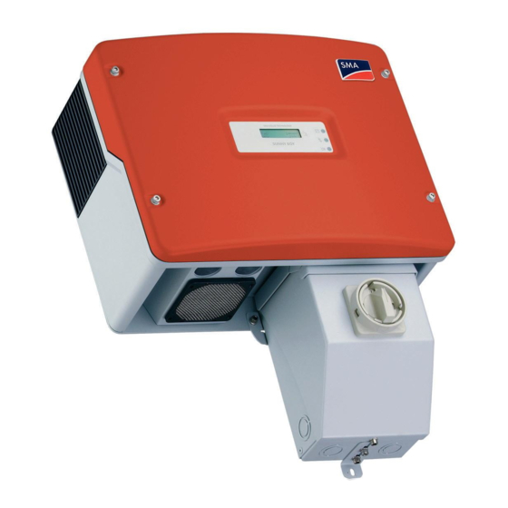
4 Product Description SMA America, LLC Product Description 4.1 Sunny Boy The Sunny Boy is a PV inverter which converts the direct current of the PV array to alternating current and feeds it into the power distribution grid. Figure 3:... -
Page 19: Symbols On The Inverter
SMA America, LLC 4 Product Description Symbols on the Inverter Symbol Designation Explanation Tap symbol You can operate the display by tapping on the enclosure lid: • To switch on the backlight, tap once. • To switch to the next displayed message, tap once. -
Page 20: Type Labels
Inverter serial number Device-specific characteristics ‒ You require the information on the type label to use the inverter safely and for customer support at the SMA Service Line. The type label must be permanently affixed to the inverter. SB30-40-US-IA-en-33 Installation Manual... -
Page 21: Sma America, Llc
4 Product Description 4.2.2 DC Disconnect Type Labels The type labels provide a unique identification of the DC Disconnect. The type label is on the right- hand side of the enclosure. SMA Solar Technology AG www.sma-solar.com DC-Disconnect Engineered in Germany Item No.l... -
Page 22: Symbols On The Type Labels
DC Disconnect serial number You require the information on the type labels to use the DC Disconnect safely and for customer support at the SMA Service Line. The type labels must be permanently affixed to the DC Disconnect. Symbols on the type labels Observe the operating instructions Read the relevant documentation before working on the product. -
Page 23: Dc Disconnect
The inverter can be equipped with a communication module for wired communication with special data capture devices or a PC with corresponding software (for information on supported communication products connected to with the communication module, see www.SMA-America.com). 4.5 Ground-Fault Protective Device (GFDI) ®... -
Page 24: Arc-Fault Circuit Interrupter (Afci)
4 Product Description SMA America, LLC 4.6 Arc-Fault Circuit Interrupter (AFCI) ® According to the National Electrical Code , Section 690.11, the Sunny Boy has a system for electric arc detection and interruption. An electric arc with a power of 300 W or greater must be interrupted by the AFCI in the time specified by UL 1699B. -
Page 25: Mounting
SMA America, LLC 5 Mounting Mounting 5.1 Safety during Mounting Risk of injury due to inverter falling over Potential risk of bruising and broken bones due to the heavy weight of the inverter. • When mounting the inverter, note that it has a weight of 88 lb. (40 kg). -
Page 26: Selecting The Mounting Location
5 Mounting SMA America, LLC 5.2 Selecting the Mounting Location Requirements for the mounting location: Danger to life due to fire or explosions With electrical devices, there is always a certain danger that a fire may break out. • Do not mount the inverter in the vicinity of combustible materials. - Page 27 SMA America, LLC 5 Mounting Wall mounting bracket dimensions: Figure 8: Dimensions of the wall mounting bracket Observe recommended clearances: Figure 9: Recommended clearances for mounting the inverter Installation Manual SB30-40-US-IA-en-33...
- Page 28 5 Mounting SMA America, LLC • If the inverter is mounted outdoors, the clearance below the inverter must amount to 3 ft. (900 mm). This prevents the ingress of waterspray into the inverter. • Observe minimum clearances to the walls as well as to other inverters or objects. This ensures adequate heat dissipation and sufficient space.
-
Page 29: Mounting The Wall Mounting Bracket On A Stone Wall
SMA America, LLC 5 Mounting 5.3 Mounting the Wall Mounting Bracket on a Stone Wall Additional required mounting material (not included in the scope of delivery): ☐ 3 screws suitable for the foundation. ☐ 3 washers suitable for the screws. -
Page 30: With A Stud Or A Post
5 Mounting SMA America, LLC 5.4 Mounting the Wall Mounting Bracket on a Wooden Wall with a Stud or a Post Additional required mounting material (not included in the scope of delivery): ☐ 3 screws suitable for the foundation. ☐ 3 washers suitable for the screws. -
Page 31: Mounting The Wall Mounting Bracket On A Wooden Wall With Two Studs Or On Two Posts
SMA America, LLC 5 Mounting 5.5 Mounting the Wall Mounting Bracket on a Wooden Wall with two Studs or on two Posts Additional required mounting material (not included in the scope of delivery): ☐ 2 screws suitable for the foundation. -
Page 32: Mounting The Dc Disconnect
5 Mounting SMA America, LLC 5.6 Mounting the DC Disconnect 5.6.1 Inserting the DC Varistors To protect inverters with an arc-fault circuit interrupter from overvoltage, the provided DC varistors must be inserted into the intended terminals prior to mounting the DC Disconnect. -
Page 33: Mounting The Dc Disconnect On The Wall
SMA America, LLC 5 Mounting 2. Equip the 3 terminals with DC varistors: • Insert the insertion tool into the rectangular opening of the terminal. • Insert the DC varistor into the terminal. • Pull the insertion tool out of the rectangular opening of the terminal. -
Page 34: Mounting The Inverter
5 Mounting SMA America, LLC 5.7 Mounting the Inverter 1. Transport the inverter using the side handles and hook the inverter into the wall mounting bracket from above. Ensure that the inverter is positioned in the center of the wall mounting bracket. -
Page 35: Electrical Connection
SMA America, LLC 6 Electrical Connection Electrical Connection 6.1 Safety During Electrical Connection Danger to life due to high voltages in PV modules that are exposed to light Death or serious injury due to electric shock as a result of touching a DC cable. -
Page 36: Overview Of The Connection Area
6 Electrical Connection SMA America, LLC 6.2 Overview of the Connection Area 6.2.1 Interior Connection Area Figure 12: Components and connection areas in the interior of the inverter and the DC Disconnect Position Designation Explanation Pin header For connecting the jumper when grounding the... -
Page 37: Connection Area Of The Inverter
SMA America, LLC 6 Electrical Connection 6.2.2 Connection Area of the Inverter Figure 13: Terminals on the underside of the inverter Position Designation Explanation Enclosure opening with filler- For inserting the communication cable plug Enclosure opening with rubber For inserting the DC cable of the... -
Page 38: Connection Area Of The Dc Disconnect
6 Electrical Connection SMA America, LLC 6.2.3 Connection Area of the DC Disconnect Figure 14: Connection Area of the DC Disconnect Position Designation Explanation Knockout For inserting the AC cables of the power distribution grid Knockout For inserting the DC cable of the... -
Page 39: Ac Connection
SMA America, LLC 6 Electrical Connection 6.3 AC Connection 6.3.1 Inserting the AC Cables into the DC Disconnect Additional required mounting material (not included in the scope of delivery): ☐ 1 rain-tight or water-tight sleeve ( ⁄ in. (19 mm)). -
Page 40: Connecting The Ac Cables To The Dc Disconnect
6 Electrical Connection SMA America, LLC 6.3.2 Connecting the AC Cables to the DC Disconnect Figure 15: AC connecting terminal plate for connecting the power distribution grid Position Designation Screw terminal "L1" Screw terminal "L2" Screw terminal "N" Screw terminal 1. -
Page 41: Connecting The Ac Cable Of The Dc Disconnect To The Inverter
SMA America, LLC 6 Electrical Connection 6.3.3 Connecting the AC Cable of the DC Disconnect to the Inverter The power distribution grid is connected to the inverter via the DC Disconnect. Inserting the AC cable of the DC Disconnect into the inverter 1. -
Page 42: Dc Connection
6 Electrical Connection SMA America, LLC 1. Connect the black insulated conductor to screw terminal "L1" (torque: 15 in-lb. (1.7 Nm)). 2. Connect the red insulated conductor to screw terminal "L2" (torque: 15 in-lb. (1.7 Nm)). 3. Connect the white insulated conductor to screw terminal "N" (torque: 15 in-lb. (1.7 Nm)). -
Page 43: Grounding The Dc Disconnect
SMA America, LLC 6 Electrical Connection 1. Disconnect the AC miniature circuit-breaker and ensure that it cannot be reconnected. 2. Open the DC Disconnect (see Section 9.3). 3. Break out a suitable knockout on the underside of the DC Disconnect for inserting the DC cable of the PV array. -
Page 44: Grounding The Dc Input
6 Electrical Connection SMA America, LLC 1. Connect the PV ground terminal to the PV protective conductor (torque: 15 in-lb. (1.7 Nm)). 2. If a DC protective conductor is prescribed, connect the DC protective conductor to the DC ground terminal (torque: 15 in-lb. (1.7 Nm)). - Page 45 SMA America, LLC 6 Electrical Connection • To negatively ground the DC input, insert the fuse extractor with ground fuse into the fuse holder and insert the jumper into the pin header: • Insert the fuse extractor with ground fuse into the upper fuse holder.
-
Page 46: Connecting The Dc Cables To The Dc Disconnect
• Configure the DC input voltage range accordingly before connecting the PV modules to the inverter. For this purpose, use the design program "Sunny Design" for string configuration (see PC Software>Sunny Design at www.SMA-America.com). Figure 19: DC connecting terminal plates for connecting the PV array... -
Page 47: Connecting The Dc Cable Of The Dc Disconnect To The Inverter
SMA America, LLC 6 Electrical Connection 1. Ensure that the inverter is grounded as prescribed (see Section 6.4.3 "Grounding the DC Input", page 44). 2. Ensure that the DC Disconnect is grounded as prescribed (see Section 6.4.2 "Grounding the DC Disconnect", page 43). - Page 48 6 Electrical Connection SMA America, LLC Connecting the DC cable of the DC disconnect to the inverter Figure 20: DC+ and DC − connecting terminal plates for connecting the DC cable of the DC Disconnect Position Designation Screw terminal DC+ Screw terminal DC −...
-
Page 49: Connecting The Combiner Box To The Dc Disconnect
SMA America, LLC 6 Electrical Connection 6.5 Connecting the Combiner Box to the DC Disconnect Figure 21: Terminals for the Combiner Box Position Designation "COMBINED" spring terminal "GROUNDED" screw terminal Connecting the DC cable to the "COMBINED" spring terminal Requirement: ☐... - Page 50 6 Electrical Connection SMA America, LLC 2. Press the insulated screwdriver upward and insert the stripped cable into the spring terminal. 3. Remove the insulated screwdriver from the spring terminal. 4. Carefully pull the cable to ensure that it is correctly connected.
-
Page 51: Configuration
SMA America, LLC 7 Configuration Configuration 7.1 Automatic Line Voltage Detection The inverter automatically detects the line voltage that it must feed in. Depending on the voltage and the phase angle between L1-N and L2-N, the inverter determines whether it is connected to a 208 V or 240 V power distribution grid. -
Page 52: Possible Grounding Systems
7 Configuration SMA America, LLC 7.2 Possible Grounding Systems The image illustrates the permitted and prohibited grounding systems in which the inverter can be operated. Tip: When connecting the inverter to the power distribution grid, the phase relationship is not important, but the voltage must be compatible. -
Page 53: Jumper Assignments For Grounding Systems
SMA America, LLC 7 Configuration 7.3 Jumper Assignments for Grounding Systems At the factory, the inverter is configured for connection to the power distribution grid via a neutral conductor. By setting the jumper, the inverter can be configured for various grounding systems. This means it is possible to connect the inverter to grounding systems without a neutral conductor (e.g. - Page 54 7 Configuration SMA America, LLC The inverter is compatible with grounding systems with a 208 V AC output or a 240 V AC output. Example: Jumper assignment for 240 V Delta: 120 V Stinger The example shows the jumper assignment for the connection of 3 inverters to a 240 Delta: 120 V Stinger power distribution grid.
-
Page 55: Changing The Display Language
SMA America, LLC 7 Configuration 7.4 Changing the Display Language You can change the display language of the inverter. The language is configured via two switches that are located on the bottom edge of the display. Figure 24: Switch for setting the language on the bottom edge of the display... -
Page 56: Commissioning The Inverter
8 Commissioning the Inverter SMA America, LLC Commissioning the Inverter Always commission the inverter according to the following procedure. Requirements: ☐ The AC miniature circuit-breaker must be correctly rated. ☐ All cables must be correctly connected. ☐ The enclosure lid must be closed and correctly grounded. -
Page 57: Opening And Closing
SMA America, LLC 9 Opening and Closing Opening and Closing 9.1 Opening the Inverter Danger to life due to high voltages in the inverter High voltages capable of causing electric shocks are present in the conductive components of the inverter. -
Page 58: Closing The Inverter
9 Opening and Closing SMA America, LLC 4. Remove all 4 screws and conical spring washers from the enclosure lid and remove the enclosure lid in an upward direction. 5. The enclosure lid, screws, and conical spring washers are to be stored safely. -
Page 59: Opening The Dc Disconnect
SMA America, LLC 9 Opening and Closing 2. Attach the enclosure lid to the enclosure using all 4 screws and conical spring washers: • Attach 1 conical spring washer on each screw. Here, the grooved side of the conical spring washer must point to the screw head. - Page 60 9 Opening and Closing SMA America, LLC 3. If additional DC switch-disconnectors are available, switch off the DC switch-disconnectors and secure against re-connection. 4. Loosen the screw on the rotary switch of the DC Disconnect. Use a cross-head screwdriver for this.
-
Page 61: Closing The Dc Disconnect
SMA America, LLC 9 Opening and Closing 7. Remove the cover of the DC Disconnect. 9.4 Closing the DC Disconnect Always close the DC Disconnect as per the following procedure. 1. If a Combiner Box is not connected, ensure that the fuse extractors with string fuses are securely positioned in the fuse holders of the DC Disconnect (see Section 11.8 "Replacing String... - Page 62 9 Opening and Closing SMA America, LLC 4. Turn the rotary switch of the DC Disconnect to the Off position. 5. Tighten the screw on the right-hand side of the rotary switch. Use a cross-head screwdriver for this. 6. Attach the conical spring washer on the screw of the DC Disconnect.
-
Page 63: Troubleshooting
SMA America, LLC 10 Troubleshooting 10 Troubleshooting 10.1 LED Signals The LEDs represent the current operating state of the inverter clarify the messages in the display by means of the various blink codes. Figure 25: Position of the LEDs Position... - Page 64 10 Troubleshooting SMA America, LLC Position Designation Status Explanation Red LED Glowing Tripped ground fuse Ground fuse was tripped or is not available. Corrective measures: • Check the PV plant for ground-faults (see Section 11.6). Yellow LED Glowing Control System Fault The operation of the inverter is permanently inhibited.
-
Page 65: Measurement Channels
SMA America, LLC 10 Troubleshooting Position Designation Status Explanation Glows for 5 s, High DC input voltage goes out for 3 s, The inverter has detected a DC input voltage blinks 4 times that is too high for safe operation. -
Page 66: Operating Parameters
10 Troubleshooting SMA America, LLC Measurement channel Explanation h-Total Total number of feed-in operation hours I-dif Residual current Line current DC input current Max Temperature Measured maximum temperature at IGBT module Max Vpv Maximum DC input voltage Mode Current operating mode... - Page 67 SMA America, LLC 10 Troubleshooting Name Description Value/range Explanation Default value CO2-Fact The inverter assesses the 0 lb./kWh to 2 lb./ 1.7 lb./kWh yield and displays the approximate amount of that the inverter has saved. The amount of CO calculated by multiplying...
- Page 68 10 Troubleshooting SMA America, LLC Name Description Value/range Explanation Default value Fac-delta+* Maximum permissible 0 Hz to 4.5 Hz 0.49 Hz frequency deviation (for the above the power country frequency of 60 Hz setting USA/ before the grid monitoring UL1741/...
- Page 69 SMA America, LLC 10 Troubleshooting Name Description Value/range Explanation Default value Memory Function no function no function Default param. Sets all parameters to the standard value. Reset Op.Data Sets all parameters that are visible on the user level to the standard values.
- Page 70 10 Troubleshooting SMA America, LLC Name Description Value/range Explanation Default value T-Start-Fan Fan turn-on temperature at 32°F to 212°F 122°F minimum speed. (0°C to 100°C) (50°C) T-Stop Time during which the 1 s to 1,800 s inverter waits before disconnecting from the power distribution grid if "Pac"...
- Page 71 SMA America, LLC 10 Troubleshooting Name Description Value/range Explanation Default value Vac-Max* Additional monitoring of 0% to 20% the AC voltage The value is used to calculate the upper limit of the permissible AC voltage. The standard value is optimal for plants ˂...
- Page 72 10 Troubleshooting SMA America, LLC Name Description Value/range Explanation Default value Vac-Max-Recnet The value is used to 0% to 20% 5.83% calculate the upper limit that is required for reconnecting to the power distribution grid after a grid failure. Vpv-Start...
-
Page 73: Display Messages
SMA America, LLC 10 Troubleshooting 10.4 Display messages 10.4.1 Status Messages Message Explanation Derating Reduction of the power fed into the power distribution grid due to high heat sink temperatures Disturbance Displays an error status that concerns the power distribution grid. This error status resolves itself. -
Page 74: Error Messages
Cause and corrective measures Bfr-Srr Communication between micro-controllers is interrupted. Corrective measures: • Contact the SMA Service Line (see Section 15). Derating The inverter reduces its output power due to excess temperature. Corrective measures: • Clean the fan (see Section 11.2). - Page 75 Corrective measures: • Contact the SMA Service Line (see Section 15). OFFSET Grid monitoring self-test failed. Corrective measures: • If the message occurs frequently, contact the SMA Service Line (see Section 15). Installation Manual SB30-40-US-IA-en-33...
- Page 76 Message Cause and corrective measures Internal test of the inverter control system firmware failed. Corrective measures: • If the message occurs frequently, contact the SMA Service Line (see Section 15). Shut-Down Overcurrent present at the DC input of the inverter.
-
Page 77: Resetting "Error Afci" Disturbance
• If the AFCI self-test continues to be unsuccessful, turn the rotary switch of the DC Disconnect to the Off position and switch off the AC miniature circuit-breaker. • If the AFCI self-test is consistently unsuccessful, contact the SMA Service Line (see Section 15 "Contact", page 99). -
Page 78: Cleaning And Care
11 Cleaning and Care SMA America, LLC 11 Cleaning and Care 11.1 Cleaning the Ventilation Grids For optimal heat dissipation of the device, the ventilation grids must be clean. 1. Remove the ventilation grids sideways. Risk of damage to the inverter due to intrusion of foreign bodies If the ventilation grid has been removed, foreign bodies (e.g. -
Page 79: Cleaning The Fans
SMA America, LLC 11 Cleaning and Care 11.2 Cleaning the Fans If the inverter displays the message "Derating", the fan may be dirty or defective. Always clean the fan as per the following procedure. 1. Open the inverter (see Section 9.1). - Page 80 11 Cleaning and Care SMA America, LLC • Unlock and remove the fan plug. Damage to the fan due to compressed air • Clean the fan with a soft brush, a paint brush, or a damp cloth. 5. Insert the fan plug into the jack until it snaps into place.
-
Page 81: Checking The Fan
☐ A communication product, data logger, or item of software, which is suitable for the type of communication used, must be available. 1. Request the installer password from the SMA Service Line (see Section 15 "Contact", page 99). 2. Launch the user interface of the data logger or the software. -
Page 82: Checking The Dc Disconnect
PV plant is not equipped with additional overvoltage protection. In such cases, SMA recommends replacing DC varistors with new ones after an operating period of 10 years in order to ensure that the functionality of the DC varistors remains at a constant level. - Page 83 SMA America, LLC 11 Cleaning and Care Figure 26: Position of the DC varistors and string fuses Position Designation Explanation DC varistors ‒ Fuse holder For connecting 4 fuse extractors with string fuses Requirement: ☐ Set with 3 replacement varistors including insertion tool must be available (see Section 13 "Accessories", page 97).
- Page 84 11 Cleaning and Care SMA America, LLC If no voltage is present at the DC varistors, replace all DC varistors. • Insert the insertion tool into the rectangular opening of the terminal. • Remove the DC varistor. • Insert the new DC varistor into the terminal.
-
Page 85: Checking The Pv Plant For A Ground-Fault
SMA America, LLC 11 Cleaning and Care 11.6 Checking the PV Plant for a ground-fault If the red and yellow LEDs glow, there may be a ground-fault in the PV plant. Check each string of the PV plant for a ground-fault as per the following procedure: Danger to life due to electric shock Death or serious injuries due to high voltages at the PV array. -
Page 86: Replacing The Ground Fuse
11 Cleaning and Care SMA America, LLC Example: Location of the ground-fault The example shows a ground-fault between the second and third PV modules. Figure 27: ground-fault in the PV array 3. Close the DC Disconnect (see Section 9.4). 4. Commission the inverter (see Section 8). - Page 87 SMA America, LLC 11 Cleaning and Care Figure 28: Position of the ground fuse Position Designation Fuse extractor with ground fuse Additional required mounting material (not included in the scope of delivery): ☐ 1 functional and correctly designed ground fuse must be available 1.
-
Page 88: Replacing String Fuses
11 Cleaning and Care SMA America, LLC 11.8 Replacing String Fuses Danger to life due to high voltages in the PV plant Death or serious injury due to electric shock. • Only replace string fuses in the inverter with fuse extractors. - Page 89 SMA America, LLC 11 Cleaning and Care Additional required mounting material (not included in the scope of delivery): ☐ 4 functional and correctly rated string fuses must be available. 1. Open the DC Disconnect (see Section 9.3 "Opening the DC Disconnect", page 59).
-
Page 90: Technical Data
12 Technical Data SMA America, LLC 12 Technical Data 12.1 DC⁄AC 12.1.1 Sunny Boy 3000-US DC input Maximum MPP voltage at 208 V nominal value 180 V to 400 V Maximum MPP voltage at 240 V nominal value 200 V to 400 V... - Page 91 SMA America, LLC 12 Technical Data Efficiency Power factor at nominal power Inverter peak efficiency 96.8% CEC efficiency at 208 V nominal value 95.0% CEC efficiency at 240 V nominal value 95.5% Figure 30: Efficiency curve SB 3000US/3000US - 12...
-
Page 92: Sunny Boy 3800-Us
12 Technical Data SMA America, LLC 12.1.2 Sunny Boy 3800-US DC input Maximum MPP voltage at 240 V nominal value 250 V to 480 V Input operating voltage range 250 V to 600 V Maximum PV array input power 5,000 W... -
Page 93: Sunny Boy 4000-Us
SMA America, LLC 12 Technical Data Figure 31: Efficiency curve SB 3800-US-10/3800-US-12 12.1.3 Sunny Boy 4000-US DC input Maximum MPP voltage at 208 V nominal value 220 V to 480 V Maximum MPP voltage at 240 V nominal value 250 V to 480 V... - Page 94 12 Technical Data SMA America, LLC AC output AC operating voltage range at 208 V nominal value 183 V to 229 V AC operating voltage range at 240 V nominal value 211 V to 264 V AC operating frequency range 59.3 Hz to 60.5 Hz...
-
Page 95: General Data
SMA America, LLC 12 Technical Data Figure 32: Efficiency curve SB 4000US/4000US - 12 12.2 General Data Width x height x depth ⁄ in. x 13 ⁄ in. x 9 ⁄ (462 mm x 351 mm x 236 mm) Weight 88 lb. -
Page 96: Protection Devices
DC reverse polarity protection Short-circuit diode AC short-circuit current capability Software-controlled AC overcurrent protection Current-controlled ® Grid monitoring (SMA Grid Guard 12.4 DC Disconnect Maximum DC input current 30 A Maximum DC short-circuit current 36 A Maximum system voltage 600 V... -
Page 97: Tripping Limits/Tripping Times
Tripping frequency accuracy: ±0.1% of nominal frequency 13 Accessories You will find the corresponding accessories and spare parts for your product in the following overview. If required, these can be ordered from SMA or your specialty retailer. Name Brief description... -
Page 98: Compliance Information
• Connect the equipment into an outlet on a circuit different from that to which the receiver is connected. • Consult the dealer or an experienced radio/TV technician for help. The user is cautioned that changes or modifications not expressly approved by SMA America, Inc. could void the user’s authority to operate this equipment. IC Compliance This device complies with Industry of Canada license-exempt RSS standard(s). -
Page 99: Contact
SMA America, LLC 15 Contact 15 Contact If you have technical problems concerning our products, contact the SMA Service Line. We require the following data in order to provide you with the necessary assistance: • Inverter device type • Inverter serial number •...