
Related Manuals for AXIOMTEK SBC86831 Series


Summary of Contents for AXIOMTEK SBC86831 Series
- Page 1 SBC86831 Series ® ® Intel Intel Yonah & Merom Core 2 Duo/Core Duo/Core Solo All-In-One Mini ITX Board User’s Manual...
- Page 2 AXIOMTEK does not warrant or assume any legal liability or responsibility for the accuracy, completeness or usefulness of any information in this document. AXIOMTEK does not make any commitment to update the information in this manual.
-
Page 3: Esd Precautions
Wear a wrist-grounding strap, available from most electronic component stores, when handling boards and components. Trademarks Acknowledgments AXIOMTEK is a trademark of AXIOMTEK Co., Ltd. ® Windows is a trademark of Microsoft Corporation. Phoenix & AWARD are trademarks of Phoenix Technology Ltd. -
Page 4: Table Of Contents
Table of Contents Disclaimers ......................ii ESD Precautions ....................iii Chapter 1 Introduction ..............1 Specifications ..................2 Utilities Supported ................... 4 Chapter 2 Jumpers and Connectors ..........5 Board Dimensions and Fixing Holes ............5 Board Layout ................... 7 Jumper Settings .................. - Page 5 Chapter 3 Hardware Description..........39 Microprocessors ..................39 BIOS...................... 39 System Memory..................39 I/O Port Address Map................40 Interrupt Controller ................41 Chapter 4 Award BIOS Utility ............43 Entering Setup..................43 Control Keys ..................44 Getting Help ..................44 The Main Menu ..................
- Page 6 MEMO...
-
Page 7: Chapter 1 Introduction
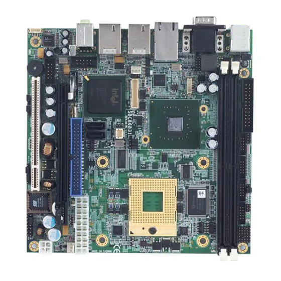
SBC86831 Series All-In-One Mini ITX Board User’s Manual C h a p t e r 1 Introduction ® The SBC86831, a Mini ITX board, supports Socket M (478) for Intel Yonah & Merom Core 2 Duo, Core Duo, Core Solo processors with FSB533/667MHz and graphics, audio, and Gigabit Ethernet interfaces. -
Page 8: Specifications
SBC86831 Series All-In-One Mini ITX Board User’s Manual Specifications ® CPU: Socket M (478-pin) for Intel Yonah & Merom Core Duo, Core Duo and Core Solo processors ® Chipset: Intel 945GME & ICH7M Bus Clock: 533/677MHz FSB BIOS Phoenix-Award BIOS, Y2K compliant... - Page 9 SBC86831 Series All-In-One Mini ITX Board User’s Manual ® Real Time Clock Integrate Intel ICH*7M Watchdog Timer 1~255 seconds; up to 255 levels Graphics/Streaming ® Intel 945GME GMCH Gen 3.5 integrated graphic engine Maximum up to 224MB frame buffer sharing system...
-
Page 10: Utilities Supported
SBC86831 Series All-In-One Mini ITX Board User’s Manual Utilities Supported Chipset Driver Ethernet Driver Graphic Drivers Audio Drivers Introduction... -
Page 11: Chapter 2 Jumpers And Connectors
SBC86831 Series All-In-One Mini ITX Board User’s Manual C h a p t e r 2 Jumpers and Connectors Board Dimensions and Fixing Holes Component Side Jumpers and Connectors... - Page 12 SBC86831 Series All-In-One Mini ITX Board User’s Manual Solder Side Jumpers and Connectors...
-
Page 13: Board Layout
SBC86831 Series All-In-One Mini ITX Board User’s Manual Board Layout Component Side Jumpers and Connectors... - Page 14 SBC86831 Series All-In-One Mini ITX Board User’s Manual Solder Side Jumpers and Connectors...
-
Page 15: Jumper Settings
SBC86831 Series All-In-One Mini ITX Board User’s Manual Jumper Settings Proper jumer settings configure the SBC86831 to meet your application purpose. We are herewith listing a summary table of all jumpers and default settings for onboard devices, respectively. Jumper Default Setting... -
Page 16: Com1 Mode Select Jumper: Jp1, Jp2, Jp3
SBC86831 Series All-In-One Mini ITX Board User’s Manual 2.3.1 COM1 Mode Select Jumper: JP1, JP2, JP3 These jumpers select the COM1 port’s communication mode to operate RS-232 or RS-422/485. Description Function Jumper Setting COM1 Mode RS-232 Select (Default) RS-422 RS-485... -
Page 17: Com1~Com4 Mode Select For Type Jumpers
SBC86831 Series All-In-One Mini ITX Board User’s Manual 2.3.2 COM1~COM4 Mode Select for Type Jumpers: JP4, JP5, JP6, JP7 Description Function Jumper Setting Pin 1=12V COM1 (CN7) Pin 1=5V *Pin 1=DCD (Default) Pin 9=12V Pin 9=5V *Pin 9=RI (Default) Jumpers and Connectors... - Page 18 SBC86831 Series All-In-One Mini ITX Board User’s Manual Description Function Jumper Setting Pin 1=12V COM2 (CN2) Pin 1=5V *Pin 1=DCD (Default) Pin 8=12V Pin 8=5V *Pin 8=RI (Default) Jumpers and Connectors...
- Page 19 SBC86831 Series All-In-One Mini ITX Board User’s Manual Description Function Jumper Setting COM3 (CN3) Pin 1=12V Pin 1=5V *Pin 1=DCD (Default) Pin 8=12V Pin 8=5V *Pin 8=RI (Default) Jumpers and Connectors...
- Page 20 SBC86831 Series All-In-One Mini ITX Board User’s Manual Description Function Jumper Setting COM4 (CN4) Pin 1=12V Pin 1=5V *Pin 1=DCD (Default) Pin 8=12V Pin 8=5V *Pin 8=RI (Default) Jumpers and Connectors...
-
Page 21: Cpu Frequency Select Jumpers: Jp8, Jp9, Jp10
SBC86831 Series All-In-One Mini ITX Board User’s Manual 2.3.3 CPU Frequency Select Jumpers: JP8, JP9, JP10 These jumpers help you set the CPU frequency. Description Function Jumper Setting CPU Frequency Auto (Default) JP10 Select FSB 533 MHz JP10 FSB 667 MHz JP10 2.3.4... -
Page 22: Cmos Clear Jumper: Jp14
SBC86831 Series All-In-One Mini ITX Board User’s Manual 2.3.5 CMOS Clear Jumper: JP14 You may need to use this jumper is to clear the CMOS memory if incorrect settings in the Setup Utility. Description Function Jumper Setting CMOS Clear Normal (Default) -
Page 23: Compactflash Tm Mode Selection Jumper: Jp16
SBC86831 Series All-In-One Mini ITX Board User’s Manual 2.3.7 CompactFlash Mode Selection Jumper: JP16 (Optional) Use this jumper to select the Master or Slave CompactFlash interface. Description Function Jumper Setting CompactFlash Slave (Default) JP16 Mode (Master/Slave) Selection Master JP16 This jumper is optional. It is not mounted as a default design. -
Page 24: Usb Power Selection Jumper: Jp18, Jp19
SBC86831 Series All-In-One Mini ITX Board User’s Manual 2.3.9 USB Power Selection Jumper: JP18 (for CN17), JP19 (for CN19) Use this jumper to select the voltage for USB interface. Description Function Jumper Setting USB Power 5V_SBY JP18, JP19 Selection 5V (Default) JP18, JP19 2.3.10 PCI-Express x16 Select Jumper: JP20... -
Page 25: Connectors
SBC86831 Series All-In-One Mini ITX Board User’s Manual Connectors Connectors connect the board with other parts of the system. Loose or improper connection might cause problems. Make sure all connectors are properly and firmly connected. Here is a summary table shows you all connectors on the SBC86831 Series. -
Page 26: Print Port Or Floppy Connector: Cn1
SBC86831 Series All-In-One Mini ITX Board User’s Manual Connectors Label SM BUS Connector JP13 Slim PCI Slot PCI1 PCI- EXPRESS X16 Slot PCIE1 -- End of Connectors Table -- 2.4.1 Print Port or Floppy Connector: CN1 Print Port Connector [Default] This board has a multi-mode parallel port to support: 1. - Page 27 SBC86831 Series All-In-One Mini ITX Board User’s Manual Floppy Connector [Optional] You can plug one end of FDD cable in the FDD connector, and the other end of cable to the FDD drive. It supports the types of FDD drives 360KB, 720KB, 1.2MB, 1.44MB and 2.88MB.
-
Page 28: Serial Port Connectors: Cn2, Cn3, Cn4
SBC86831 Series All-In-One Mini ITX Board User’s Manual 2.4.2 Serial Port Connectors: CN2, CN3, CN4 Please refer to the RS-232 pin assignment as listed below: Description Description CN2, CN3, CN4 Data Carrier Detect Data Set Ready (DCD) (DSR) Request to Send... -
Page 29: Keyboard And Ps/2 Mouse Connector: Cn6
SBC86831 Series All-In-One Mini ITX Board User’s Manual 2.4.4 Keyboard and PS/2 Mouse Connector: CN6 The board provides a keyboard and Mouse interface with a DIN connector. Signal Signal K/B Data M/S Data K/B CLK M/S CLK M/S Data M/S CLK 2.4.5 VGA &... -
Page 30: Lvds Backlight Connector: Cn8
SBC86831 Series All-In-One Mini ITX Board User’s Manual Description Green Blue CN7B Ground (GND) AnalogGround AGND AnalogGround AGND AnalogGround AGND N.C. Ground (GND) N.C. DDC DATA Horizontal Sync Vertical Sync DDC CLK 2.4.6 LVDS Backlight Connector: CN8 This is a 7-pin connector for inverter on the board that we strongly recommend you to use the matching DF13-7S-1.25C connector. -
Page 31: Lan1*2 Connectors: Cn9_A, Cn9_B
SBC86831 Series All-In-One Mini ITX Board User’s Manual 2.4.7 LAN*2 Connectors: CN9_A, CN9_B Signal CN9_A MDI0+ MDI0- MDI1+ MDI1- MDI2+ MDI2- MDI3+ MDI3- Active LED (Yellow) 1000 (Orange) / 100 (Green) LAN Signal CN9_B MDI0+ MDI0- MDI1+ MDI1- MDI2+ MDI2-... -
Page 32: Usb*2 + Ieee1394 Connectors: Cn10, Cn13
SBC86831 Series All-In-One Mini ITX Board User’s Manual 2.4.8 USB*2 + IEEE1394 Connectors: CN10, CN13 Signal +12V CN10A, CN13A XTPB0N XTPB0P XTPA0N XTPA0P Signal CN10B, CN13B USB D0- USB D0+ USB D1- USB D1+ Jumpers and Connectors... -
Page 33: Lvds Flat Panel Connector: Cn11
SBC86831 Series All-In-One Mini ITX Board User’s Manual 2.4.9 LVDS Flat Panel Connector: CN11 Signal Signal VCCM VCCM VCCM VCCM VCCM VCCM N.C. N.C. Channel B D3- Channel B D0- Channel B D3+ Channel B D0+ Channel B CLK- Channel B D1-... -
Page 34: Sata Connectors: Cn14, Cn15
SBC86831 Series All-In-One Mini ITX Board User’s Manual 2.4.10 SATA Connectors: CN14, CN15 Signal CN14, CN15 SATA_TX+ SATA_TX- SATA_RX- SATA_RX+ 2.4.11 Audio Phone Jack Connector: CN16 Signal CN16 AUDIO_GND MIC_IN1 MIC_IN MIC_IN2 LINE_OUT_L LINE_OUT_L1 LINE_OUT_R1 LINE_OUT_R 2.4.12 USB Connectors: CN17, CN19 These Universal Serial Bus (USB) connectors on this board are for installing versatile USB interface peripherals. -
Page 35: Parallel Ide Connector: Cn18
SBC86831 Series All-In-One Mini ITX Board User’s Manual Signal Signal CN17 UDB4- USB5- USB4+ USB5+ Ground (GND) Ground (GND) Ground (GND) Ground (GND) CN19 Signal Signal UDB7- USB6- USB7+ USB6+ Ground (GND) Ground (GND) Ground (GND) Ground (GND) 2.4.13 Parallel IDE Connector: CN18... -
Page 36: Flat Panel Bezel Connector: Cn20
SBC86831 Series All-In-One Mini ITX Board User’s Manual 2.4.14 Flat Panel Bezel Connector: CN20 This connector (CN20) is making the connection to front panel switches and LEDs. Power LED This 3-pin connector (Pin 1, 3, 5) connects a LED indicator to the system power switch on the case. -
Page 37: Internal Audio Connector: Cn21
SBC86831 Series All-In-One Mini ITX Board User’s Manual 2.4.15 Internal Audio Connector: CN21 CN21 Signal LINE_OUT_L LINE_OUT_R MIC_IN 2.4.16 ATX Power Connector: ATX1 Signal Signal ATX1 3.3V 3.3V 3.3V -12V PS_ON PW_OK 5V_SB 2.4.17 +12V ATX Power Connector: ATX2 Signal... -
Page 38: Compactflash Tm Socket: Cfs1 (Optional)
SBC86831 Series All-In-One Mini ITX Board User’s Manual 2.4.18 CompactFlash Socket: CFS1 (Optional) The board is equipped with a CompactFlash disk type-II socket on the solder side to support an IDE interface CompactFlash disk card with DMA mode supported. The socket is especially designed to avoid incorrect installation of the CompactFlash disk card. -
Page 39: Pci-Express Mini Card Socket: Cns1 (Optional)
SBC86831 Series All-In-One Mini ITX Board User’s Manual CFS1 2.4.19 PCI-Express Mini Card Socket: CNS1 (Optional) CNS1 is a PCI Express Mini Card Socket to support both a PCI Express x1 link and a USB 2.0 link. A PCI Express Mini Card can be applied to either PCI Express or USB 2.0 (or both). -
Page 40: System & Cpu Fan Connectors: Fan1, Fan2
SBC86831 Series All-In-One Mini ITX Board User’s Manual Signal Signal PCIE_RESET- PCIE_RXN +3.3V_SBY PCIE_RXP +1.5V SMB_CLK PCIE_TXN SMB_DATA PCIE_TXP USB_D- USB_D+ +1.5V +3.3V 2.4.20 System & CPU Fan Connectors: FAN1, FAN2 FAN1 is a fan connector for system, and FAN2 for CPU. Pentium microprocessors require a fan for heat dispensing. -
Page 41: Smbus Connector: Jp13
SBC86831 Series All-In-One Mini ITX Board User’s Manual 2.4.21 SMBUS Connector: JP13 Connector JP13 is for SMBUS interface support. Signal JP13 CLOCK DATA 2.4.22 Slim PCI Slot: PCI1 Signal Signal Signal Signal A1 TRST- +12V -12V A3 TMS A5 +5V... -
Page 42: Pci-Express X16 Slot: Pcie1
SBC86831 Series All-In-One Mini ITX Board User’s Manual Signal Signal Signal Signal A45 +3.3V AD[13] AD[14] A47 AD[11] AD[12] AD[10] A49 AD[9] C/BE- AD[6] A53 +3.3V AD[6] AD[7] +3.3V A55 AD[4] AD[5] AD[3] A57 AD[2] AD[0] AD[1] A59 +5V REQ64-... -
Page 43: Jumpers And Connectors
SBC86831 Series All-In-One Mini ITX Board User’s Manual Signal Signal Signal Signal A25 PEG_RXP2 A26 PEG_RXN2 B25 GND B26 GND A27 GND A28 GND B27 PEG_TXP3 B28 PEG_TXN3 A29 PEG_RXP3 A30 PEG_RXN3 B29 GND B30 N.C A31 GND A32 N.C B31 N.C... - Page 44 SBC86831 Series All-In-One Mini ITX Board User’s Manual PCIE1 Jumpers and Connectors...
-
Page 45: Chapter 3 Hardware Description
CPU from damages. BIOS The SBC86831 Series uses Award Plug and Play BIOS with a single 16Mbit SPI Flash EPROM. System Memory The SBC86831 Series industrial CPU card supports two 240-pin DDR2 DIMM sockets for a maximum memory of 4GB DDR2 SDRAMs. -
Page 46: I/O Port Address Map
SBC86831 Series All-In-One Mini ITX Board User’s Manual I/O Port Address Map ® The Intel Yonah & Merom Core 2 Duo, Core Duo, and Core Solo CPUs can communicate via I/O ports. There are total 1KB port addresses available for assignment to other devices via I/O expansion cards. -
Page 47: Interrupt Controller
SBC86831 Series All-In-One Mini ITX Board User’s Manual Interrupt Controller The SBC86831 Series is a 100% PC compatible control board. It consists of 16 interrupt request lines, and four out of them can be programmable. The mapping list of the 16 interrupt request lines is shown as the following table. - Page 48 SBC86831 Series All-In-One Mini ITX Board User’s Manual MEMO Hardware Description...
-
Page 49: Chapter 4 Award Bios Utility
SBC86831 Series All-In-One Mini ITX Board User’s Manual C h a p t e r 4 Award BIOS Utility The Phoenix-Award BIOS provides users with a built-in Setup program to modify basic system configuration. All configured parameters are stored in a battery-backed-up RAM (CMOS RAM) to save the Setup information whenever the power is turned off. -
Page 50: Control Keys
SBC86831 Series All-In-One Mini ITX Board User’s Manual Control Keys Move cursor to the previous item Up arrow Move cursor to the next item Down arrow Move cursor to the item on the left hand Left arrow Move to the item in the right hand... -
Page 51: The Main Menu
SBC86831 Series All-In-One Mini ITX Board User’s Manual The Main Menu Once you enter the Award BIOS CMOS Setup Utility, the Main Menu appears on the screen. In the Main Menu, there are several Setup functions and a couple of Exit options for your selection. Use arrow keys to select the Setup Page you intend to configure then press <Enter>... -
Page 52: Standard Cmos Setup Menu
SBC86831 Series All-In-One Mini ITX Board User’s Manual Standard CMOS Setup Menu The Standard CMOS Setup Menu displays basic information about your system. Use arrow keys to highlight each item, and use <PgUp> or <PgDn> key to select the value you want in each item. - Page 53 SBC86831 Series All-In-One Mini ITX Board User’s Manual IDE Channel Master/IDE Channel Slave These items identify the types of each IDE channel installed in the computer. There are 45 predefined types (Type 1 to Type 45) and 2 user’s definable types (Type User) for Enhanced IDE BIOS.
- Page 54 SBC86831 Series All-In-One Mini ITX Board User’s Manual Halt On This item determines whether the system will halt or not, if an error is detected while powering up. No errors The system booting will halt on any errors detected. (default)
-
Page 55: Advanced Bios Features
SBC86831 Series All-In-One Mini ITX Board User’s Manual Advanced BIOS Features This section allows you to configure and improve your system, to set up some system features according to your preference. Award BIOS Utility... - Page 56 SBC86831 Series All-In-One Mini ITX Board User’s Manual CPU Feature Scroll to this item and press <Enter> to view the CPU Feature sub menu. Hard Disk Boot Priority Scroll to this item and press <Enter> to view the sub menu to decide the disk boot priority.
- Page 57 SBC86831 Series All-In-One Mini ITX Board User’s Manual Press <Esc> to return to the Advanced BIOS Features page. CPU L1 & L2 Cache These two options speed up memory access. However, it depends on the CPU/chipset design. The default setting is “Enabled”.
- Page 58 SBC86831 Series All-In-One Mini ITX Board User’s Manual BIOS searches for floppy disk drive to determine if it is 40 or 80 tracks. Please be noted BIOS can not Enabled differentiate 720K, 1.2M or 1.44M drive type as they all are 80 tracks.
- Page 59 SBC86831 Series All-In-One Mini ITX Board User’s Manual value is “250”. 250 msec 500 msec 750 msec 1000 1000 msec Security Option This item allows you to limit access to the system and Setup, or just to Setup. The default value is “Setup”.
-
Page 60: Advanced Chipset Features
SBC86831 Series All-In-One Mini ITX Board User’s Manual Advanced Chipset Features This section contains completely optimized chipset’s features on the board that you are strongly recommended to leave all items on this page at their default values unless you are very familiar with the technical specifications of your system hardware. - Page 61 SBC86831 Series All-In-One Mini ITX Board User’s Manual CAS and RAS strobe signals, used when DRAM is written to, read from, or refreshed. DRAM RAS# Precharge The precharge time is the number of cycles it takes for the RAS to accumulate its charge before DRAM refresh.
- Page 62 SBC86831 Series All-In-One Mini ITX Board User’s Manual PCI Express Root Port Func Scroll to this item and press <Enter> to view the sub menu to decide the PCI Express Port. Press <Esc> to return to the Advanced Chipset Featurs page, and press it again, return to the Main Menu page.
-
Page 63: Integrated Peripherals
SBC86831 Series All-In-One Mini ITX Board User’s Manual On-Chip Frame Buffer Size Use this item to set the VGA frame buffer size. DVMT Mode DVMT (Dynamic Video Memory Technology) helps you select the video mode. DVMT/Fixed Memory Size DVMT (Dynamic Video Memory Technology) allows you to select a maximum size of dynamic amount usage of the video memory. - Page 64 SBC86831 Series All-In-One Mini ITX Board User’s Manual OnChip IDE Device Scroll to this item and press <Enter> to view the sub menu OnChip IDE Device. IDE HDD Block Mode Block mode is also called block transfer, multiple commands, or multiple sector read/write. If your IDE hard drive supports...
- Page 65 SBC86831 Series All-In-One Mini ITX Board User’s Manual Slave PIO and/or IDE Secondary Master/Slave PIO items on the menu. IDE Primary/Secondary Master/Slave PIO The four IDE PIO (Programmed Input/Output) fields let you set a PIO mode (0-4) for each of the four IDE devices that the onboard IDE interface supports.
- Page 66 SBC86831 Series All-In-One Mini ITX Board User’s Manual Onboard Device Scroll to this item and press <Enter> to view the sub menu Onboard Device. USB Controller Enable this item if you are using the USB in the system. You should disable this item if a higher-level controller is added.
- Page 67 SBC86831 Series All-In-One Mini ITX Board User’s Manual Super IO Device Scroll to this item and press <Enter> to view the sub menu Super IO Device. Onboard FDC Controller Select Enabled, if your system has a floppy disk controller (FDC) installed on the system board and you want to use it.
- Page 68 SBC86831 Series All-In-One Mini ITX Board User’s Manual Serial Port 4 Use IRQ This item selects a corresponding interrupt for the fourth serial port. Onboard Paralellel Port This item allows you to determine the I/O address for onboard parallel port. Options are: “378H/IRQ7”, “278H/IRQ5”, “3BC/IRQ7”...
-
Page 69: Power Management Setup
SBC86831 Series All-In-One Mini ITX Board User’s Manual Power Management Setup The Power Management Setup allows you to save energy of your system effectively. It will shut down the hard disk and turn OFF video display after a period of inactivity. - Page 70 SBC86831 Series All-In-One Mini ITX Board User’s Manual PCI Express PM Func Scroll to this item and press <Enter> to view the sub menu PCI Express PM Function. Press <Esc> to return to the Advanced Chipset Featurs page. ACPI Function This item allows you to enable/disable the Advanced Configuration and Power Management (ACPI).
- Page 71 SBC86831 Series All-In-One Mini ITX Board User’s Manual Power Management This option allows you to select the type (or degree) of power saving for Doze, Standby, and Suspend modes. The table below describes each power management mode: It is maximum power savings, only available for SL CPUs.
- Page 72 SBC86831 Series All-In-One Mini ITX Board User’s Manual Disabled System will never enter SUSPEND mode Defines the continuous idle time before the system 1/2/4/6/8/10/2 entering SUSPEND mode. 0/30/40 If any item defined in (J) is enabled & active, Min/1 Hr...
-
Page 73: Pnp/Pci Configuration Setup
SBC86831 Series All-In-One Mini ITX Board User’s Manual FDD, COM, LPT Port Use this item to configure the FDD, COM and LPT ports monitored by the system. PCI PIRQ[A-D]# This item can be used to detect PCI device activities; if no activity, the system will enter the sleep mode. - Page 74 SBC86831 Series All-In-One Mini ITX Board User’s Manual or if installing a new add-on cause the system reconfiguration a serious conflict that the operating system can not boot. Options: Enabled, Disabled. Resources Controlled By The Award Plug and Play BIOS can automatically configure all boot and Plug and Play-compatible devices.
-
Page 75: Pc Health Status
SBC86831 Series All-In-One Mini ITX Board User’s Manual 4.11 PC Health Status This section supports hardware monitering that lets you monitor those parameters for critical voltages, temperatures and fan speed of the board. CPU Temperature The current system CPU temperature will be automatically detected by the system. -
Page 76: Frequency/Voltage Control
SBC86831 Series All-In-One Mini ITX Board User’s Manual 4.12 Frequency/Voltage Control This section is to control the CPU frequency and Supply Voltage, DIMM OverVoltage and AGP voltage. Auto Detect PCI Clk The item enables or disables the auto detection of the PCI clock. -
Page 77: Load Optimized Defaults
SBC86831 Series All-In-One Mini ITX Board User’s Manual 4.13 Load Optimized Defaults This option allows you to load your system configuration with default values. These default settings are optimized to enable high performance features. To load CMOS SRAM with SETUP default values, please enter “Y”. If not, please enter “N”. -
Page 78: Set Supervisor/User Password
SBC86831 Series All-In-One Mini ITX Board User’s Manual 4.14 Set Supervisor/User Password You can set a supervisor or user password, or both of them. The differences between them are: Supervisor password: You can enter and change the options on the setup menu. -
Page 79: Save & Exit Setup
SBC86831 Series All-In-One Mini ITX Board User’s Manual 4.15 Save & Exit Setup This section allows you to determine whether or not to accept your modifications. Type “Y” to quit the setup utility and save all changes into the CMOS memory. Type “N” to bring you back to the Setup utility. -
Page 80: Exit Without Saving
SBC86831 Series All-In-One Mini ITX Board User’s Manual 4.16 Exit Without Saving Select this option to exit the Setup utility without saving changes you have made in this session. Type “Y”, and it will quit the Setup utility without saving your modifications. Type “N” to return to the Setup utility. -
Page 81: Appendix A Watchdog Timer
SBC86831 Series All-In-One Mini ITX Board User’s Manual A p p e n d i x A Watchdog Timer Watchdog Timer Setting After the system stops working for a while, it can be auto-reset by the Watchdog Timer. The integrated Watchdog Timer can be set up in the system reset mode by program. - Page 82 SBC86831 Series All-In-One Mini ITX Board User’s Manual ; IF to disable WDT: O 2E 30 O 2F 00 ; Can be disable at any time Timeout Value Range 1 to 255 Minute / Second Program Sample Watchdog Timer can be set to system reset after 5-second timeout.
-
Page 83: Appendix B Digital I/O
SBC86831 Series All-In-One Mini ITX Board User’s Manual A p p e n d i x B Digital I/O Digital I/O Software Programming GPI program sample: O 2E 87 O 2E 87 O 2E 2A O 2F FF Setting GP10~GP17... - Page 84 SBC86831 Series All-In-One Mini ITX Board User’s Manual GPO program sample: o 2e 87 o 2e 87 o 2e 2A Setting GP10~GP17 o 2f FF o 2e 07 Select Device 7 o 2f 07 o 2e 30 Setting logic device active...