Yamaha M7CL Owner's Manual
Digital mixing console
Hide thumbs
Also See for M7CL:
- Owner's manual (312 pages) ,
- User manual (51 pages) ,
- Quick start manual (24 pages)
Table of Contents
Advertisement
Quick Links
Advertisement
Table of Contents

Related Manuals for Yamaha M7CL


Summary of Contents for Yamaha M7CL
- Page 1 Owner’s Manual...
- Page 2 Compliance with FCC * This applies only to products distributed by YAMAHA CORPORATION OF AMERICA. (class B) COMPLIANCE INFORMATION STATEMENT IMPORTANT NOTICE FOR THE UNITED KINGDOM...
-
Page 3: Important Safety Instructions
• For the removal of the battery at the moment of the disposal at the end tillverkaren. Kassera använt batteri enligt of the service life please consult your retailer or Yamaha Service Center fabrikantens instruktion. as follows:... - Page 4 Do not open the power switch, disconnect the electric plug from the outlet, and have the device inspected by qualified Yamaha service personnel. • Do not open the device or attempt to disassemble the internal parts or modify them in any way. The device contains no user-serviceable parts. If it should appear to be malfunctioning, discontinue use immediately and have it inspected by qualified Yamaha service personnel.
- Page 5 XLR-type connectors are wired as follows (IEC60268 standard): pin 1: ground, pin 2: hot (+), and pin 3: cold (-). Yamaha cannot be held responsible for damage caused by improper use or modifications to the device, or data that is lost or destroyed.
-
Page 6: Table Of Contents
9. Input/output patching Connections.............. 39 Changing the output patch settings ....... 95 Setting up to use the M7CL ........43 Changing the input patch settings ......98 Restoring the current scene Inserting an external device into a channel ..100 to the default state........... - Page 7 Recalling a scene ..........128 17. MIDI Using user-defined keys to recall ...... 129 Editing scene memories ........130 MIDI functionality on the M7CL ......181 Sorting and renaming scene memories ..... 130 Basic MIDI settings..........182 Scene memory editing ........132 Using program changes to recall scenes and library items ....
- Page 8 Using cascade connections ........210 to user-defined keys .......... 253 Operations on the cascade slave M7CL.... 210 MIDI Data Format ............ 255 Operations on the cascade master M7CL ..211 Warning/Error Messages ........262 Basic settings Troubleshooting ............. 264 for MIX buses and MATRIX buses....212 General Specifications ...........
-
Page 9: Introduction
Introduction Thank you Thank you for purchasing the Yamaha M7CL digital mixing console. In order to take full advan- tage of the M7CL’s superior functionality and enjoy years of trouble-free use, please read this manual before you begin using the product. After you have read the manual, keep it in a safe place. -
Page 10: Cascade Connections
The rear panel provides three slots in which separately sold mini-YGDAI cards can be installed. AD cards, DA A second M7CL unit or a digital mixer such as the cards, or digital I/O cards can be installed in these slots to Yamaha PM5D connected via a digital I/O card installed add inputs and outputs. -
Page 11: Differences Between The M7Cl-48 And M7Cl-32
Differences between the M7CL-48 and M7CL-32 Differences between the M7CL-48 and M7CL-32 The M7CL is available in two models; the M7CL-48 and the M7CL-32. These models differ as fol- lows. ■ M7CL-48 This model provides 48 INPUT jacks and 48 INPUT channels. - Page 12 This model provides 32 INPUT jacks and 32 INPUT channels. INPUT jacks 1–32 are located at the right side of the right panel, just as on the M7CL-48 model, but there are no INPUT jacks at the left side of the rear panel.
-
Page 13: Output Channels
These channels are used to process monaural signals. By L/C/R playback. default, the input signals from the monaural analog input When the M7CL is in the default state, the following out- jacks (INPUT jacks 1–32 {INPUT jacks 1–48}) are put ports are assigned. -
Page 14: About The Mix Bus Types (Vari / Fixed)
About the MIX bus types (VARI / FIXED) • About word clock • Conventions in this manual• About the firmware version About the MIX bus types (VARI / FIXED) The sixteen MIX buses provided on the M7CL can be assigned either as VARI or FIXED types in pairs of adjacent odd-numbered/even-numbered buses (→ p. 212). Each type has the following characteristics. -
Page 15: Panels And Controls
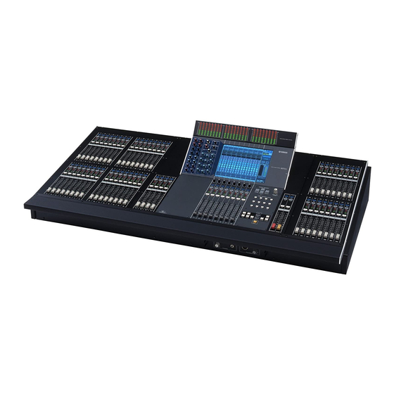
Chapter 2 Panels and controls This chapter explains the names and functions of each part of the M7CL. Top panel The top panel of the M7CL is divided into the following sections. Display section (P. 18) SCENE MEMORY/ Meter bridge (option) -
Page 16: Input Section
[CUE] key from each channel to the currently selected MIX bus. These keys select the channel to be cue-monitored. If cue is on, the LED will light. Meter LEDs These LEDs indicate the input level of the channel. M7CL Owner’s Manual... - Page 17 This adjusts the panning of the signal that is sent from For each band of the four-band EQ, these adjust the Q, the selected channel to the L/R channels (or L/C/R center frequency (cutoff frequency), and gain. channels) of the STEREO bus. M7CL Owner’s Manual...
-
Page 18: Display Section
(saved, loaded, or deleted). Do not disconnect the USB connector or power-off the M7CL while this indicator is shown. Doing so may damage your stor- age media, or may damage the data in the M7CL or on your media. M7CL Owner’s Manual... -
Page 19: Centralogic Section
[MONITOR LEVEL] knob Adjusts the signal level of the monitor output. If the PHONES LEVEL LINK function is turned on in the MONITOR screen, this will also adjust the level of the front panel [PHONES] jack. M7CL Owner’s Manual... - Page 20 This key selects the channel to be cue-monitored. If cue is on, the LED will light. [ON] key This key switches the channel on/off. If a channel is on, the key LED will light. Fader This adjusts the output level of the channel. M7CL Owner’s Manual...
- Page 21 This key assigns the STEREO channel L/R and the MONO channel to modules 1–3 of the Centralogic sec- tion. In this case, modules 4–8 are not used. [IN 33-40] key {M7CL-48 only} [IN 41-48] key {M7CL-48 only} These keys select INPUT channels 33–40 and 41–48 respectively.
-
Page 22: Rear Panel
This is a D-sub 9-pin male connector for remotely control- power to a separately sold gooseneck lamp (such as the ling an external head amp device (e.g., Yamaha AD8HR) Yamaha LA5000). {The M7CL-48 has these connectors at that supports a special protocol. It can also be used to two locations.}... - Page 23 Studio Manager required for starting up M7CL Edi- power from the PW800W even if its own internal power tor, and the M7CL Editor itself can be downloaded from the follow- supply shuts down due to a problem. ing Yamaha website.
-
Page 24: Under The Front Pad
+48V phantom power to this jack. This is used to send instructions from the mixer operator to the desired output channel. TALKBACK GAIN knob This adjusts the input level of the mic connected to the TALKBACK jack. M7CL Owner’s Manual... -
Page 25: Basic Operation Of The M7Cl
Basic operations in the top panel / touch screen This section explains the basic procedures you can perform in the M7CL’s top panel and touch screen. In general, you will operate the M7CL using the appropriate combination of the opera- tions explained here. -
Page 26: Multifunction Encoder Operations
▼ When you press a button that has a symbol, a separate window will open, allowing you to make detailed settings. M7CL Owner’s Manual... -
Page 27: Faders / Knobs
Knobs for which a double frame is displayed indicate PAN/BALANCE. HINT • For some knobs, pressing them again when they are enclosed by a heavy frame will open a window where you can make additional detailed settings. M7CL Owner’s Manual... -
Page 28: Popup Windows
Press the OK button to execute the operation. The opera- tion will be cancelled if you press the CANCEL button. Viewing the touch screen The M7CL’s touch screen shows the following information, and is broadly divided into two areas. Function access area Main area... -
Page 29: Main Area
When you press a button through to access the cor- responding screen, the button will be highlighted. In this state, pressing the button once again will return either to the most recently recalled SELECTED CHANNEL VIEW screen or the OVERVIEW screen. M7CL Owner’s Manual... -
Page 30: Entering Names
Entering names Entering names On the M7CL you can assign a name to each input channel, output channel, and DCA group, and assign a title to scene and library data when saving it. To assign a name, you will use the keyboard window shown in the screen. -
Page 31: Using The Tool Buttons
fied bus. 1 EQ graph field • ALL POST ..Specifies POST as the position from Dynamics 1/2 field which all signals are sent to the speci- fied bus. M7CL Owner’s Manual... - Page 32 / channel name buttons in the popup window. Channel number / Channel name buttons 1 RACK button Racks M7CL Owner’s Manual...
- Page 33 If you select a library number that cannot be recalled, it will not be possible to press the RECALL button. Press the LIBRARY tool button to open the corresponding library window. Library windows contain the following items. M7CL Owner’s Manual...
- Page 34 (GEQ/effect) will be stored to the NOTE position selected in the list. • Be aware that if you store settings to a location that already contains data, the existing data will be overwritten. (Read- only data cannot be overwritten.) M7CL Owner’s Manual...
-
Page 35: Initializing Settings
To execute the Clear operation, press the OK button. The data you selected in step 3 will be cleared. If you decide to cancel the Clear operation, press the CAN- CEL button instead of the OK button. M7CL Owner’s Manual... -
Page 36: Copying/Pasting Settings
• Of the two types of GEQ, using the tool buttons in a rack where a Flex15GEQ is selected will cause the settings to be copied/pasted individually. • Effect settings with an effect type of “HQ.Pitch” or “Freeze” cannot be pasted to rack 6 or 8. M7CL Owner’s Manual... - Page 37 • The settings in the buffer memory can also be used for the Paste operation. NOTE • Of the two types of GEQ, using the tool buttons in a rack where a Flex15GEQ is selected will cause the settings to be exchanged individually with the buffer memory. M7CL Owner’s Manual...
- Page 38 M7CL Owner’s Manual...
-
Page 39: Connections And Setup
Chapter 4 Connections and setup This chapter explains how to make audio input/output connections, and how to perform the setup required when starting the M7CL for the first time. Connections ■ Analog input connections MUSIC PRODUCTION SYNTHESIZER Integrated Sampling Sequencer... -
Page 40: Analog Output Connections
(C)), monitor signals (MONITOR OUT L/R/C channel), and the direct out signals of INPUT channels 1–32 {1–48}. When the M7CL is in the default state, the signals of the following channels are patched to each output port. (You are free to change this patching as desired.) - Page 41 Main speakers Use the 2TR OUT DIGITAL jack to send the M7CL’s internal signals to an external digital audio device. When the M7CL is in the default state, the output signal of the STEREO channel is patched to the 2TR OUT DIGITAL jack, and can be used to record the main mix onto a CD recorder or other device.
-
Page 42: Installing An Option Card
Before you install I/O cards in slots 1–3, you must check the Yamaha website to determine whether the card is compatible with the M7CL, and to verify the total number of Yamaha or third-party cards that can be installed in combination with that card. -
Page 43: Setting Up To Use The M7Cl
Setting up to use the M7CL This section explains the setup required when starting up the M7CL for the first time. We will also discuss basic operations for sending an input channel signal out from the STEREO bus so that you can check the connections. -
Page 44: Making Ha (Head Amp) Gain Settings
● When using word clock data from the WORD CLOCK IN jack as the clock source Press the WORD CLOCK IN button. If the M7CL is operating correctly with the new clock, the symbol immediately above the corresponding but- ton will turn light blue. - Page 45 Setting up to use the M7CL [SELECTED CHANNEL section] For example if you want to make head amp settings for INPUT jack 7, press the [SEL] key of the channel strip for INPUT channel 7. [INPUT section channel strip] 1 [HA] encoder...
- Page 46 Setting up to use the M7CL ● [IN 1-8] key While performing on the mic or instrument, ● [IN 9-16] key turn the [HA] encoder of the SELECTED ● [IN 17-24] key CHANNEL section to adjust the gain of the currently selected channel.
-
Page 47: Sending An Input Channel Signal To The Stereo Bus
Setting up to use the M7CL For example, the following illustration shows the Sending an input channel signal OVERVIEW screen for INPUT channels 1–8. The knobs of the HA/PHASE field indicate the amount of to the STEREO bus HA gain for each channel. - Page 48 Setting up to use the M7CL In the STEREO/MONO MASTER section, HINT make sure that the [ON] key of the STEREO • The signal being output from the STEREO channel can channel is on, and raise the STEREO chan- also be monitored using headphones connected to the PHONES nel fader to 0 dB.
- Page 49 Setting up to use the M7CL In the Centralogic section, verify that the [ON] of the corresponding input channel is In the STEREO/MONO MASTER section, make sure that the [ON] key of the STEREO channel is on, and raise the STEREO chan- nel fader to 0 dB.
- Page 50 M7CL Owner’s Manual...
-
Page 51: Input Channel Operations
There are two types of input channel, as follows. I INPUT channels 1–32 {1–48} These channels are used to process monaural signals. When the M7CL is in the default state, the input signals from INPUT jacks 1–32 {1–48} are assigned to these channels. - Page 52 This meters the level of the input channel. You can switch the setting of this parameter will also be applied to the sig- the position at which the level is detected. nal sent to two MIX or MATRIX buses that are set to ste- reo. M7CL Owner’s Manual...
-
Page 53: Specifying The Channel Name And Icon
Specifying the channel name and icon Specifying the channel name and icon On the M7CL, the name and icon shown in the screen can be specified for each input channel. Here we will explain how to specify the channel name and icon. - Page 54 HINT • You can press the TAB button to switch to the next channel. You can press the ENTER button to close the popup window in the same way as using the “ × ” symbol. M7CL Owner’s Manual...
-
Page 55: Making Ha (Head Amp) Settings
1 Icon / Channel number / Channel name This shows the icon, channel number, and channel name for that channel. +48V button This switches the phantom power on (red) or off (black) for the head amp assigned to this channel. M7CL Owner’s Manual... - Page 56 INPUT jack, ST IN sponding port. jack, or a slot that is connected to an external head amp device (e.g., Yamaha AD8HR). (For details on connecting ø (Phase) button external head amp devices → p. 177).
-
Page 57: Sending The Signal From An Input Channel To The Stereo/Mono Buses
[TO STEREO/MONO popup window (8 ch)] Here you can control the on/off and pan/balance set- tings of the signal sent from input channels to the STEREO (L/R) bus and MONO (C) bus, in groups of 1 STEREO/MONO field eight channels. M7CL Owner’s Manual... - Page 58 [ON] key sponding multifunction encoder. of the STEREO channel / MONO channel is turned on, and raise the fader to an appro- priate position. M7CL Owner’s Manual...
- Page 59 STEREO (L/R) bus and MONO (C) bus as shown in the following diagram. Signal sent to the MONO (C) bus Signal sent to the STEREO (L) bus Signal sent to the STEREO (R) bus PAN knob M7CL Owner’s Manual...
- Page 60 STEREO (L) bus TO ST BALANCE knob Signal sent from the ST IN (R) channel to the MONO (C) bus Signal sent from the ST IN (R) channel to the STEREO (R) bus TO ST BALANCE knob M7CL Owner’s Manual...
-
Page 61: Sending The Signal From An Input Channel To A Mix Bus
■ Using the faders of the top panel In this method, you switch the M7CL to SENDS ON FADER mode, and use the faders of the top panel to adjust the send levels to the MIX buses. When using this method, the signals sent from all input channels to a specific MIX bus can be adjusted simultaneously. - Page 62 If the send-destination MIX bus is assigned as stereo, the left knob of the two adjacent TO MIX SEND LEVEL knobs will operate as the TO MIX PAN knob (for a ST IN channel, it will operate as the TO MIX BALANCE knob). M7CL Owner’s Manual...
-
Page 63: Using The Centralogic Section
[SEL] key will These are on/off switches for the signal sent from the light. input channels to the MIX bus. These buttons are shown only when the send-destination MIX bus is a FIXED type. M7CL Owner’s Manual... -
Page 64: Using The Faders (Sends On Fader Mode)
SENDS ON FADER button. This button selects PRE as the position from which The M7CL will switch to SENDS ON FADER mode. signals are sent from all input channels to VARI-type The most recently selected group of MIX buses will be MIX buses. - Page 65 • You can assign the SENDS ON FADER function to a user- defined key. This lets you quickly switch to SENDS ON state, and the M7CL will exit SENDS ON FADER FADER mode for a specific MIX bus, and quickly switch back mode and return to normal mode.
-
Page 66: Sending The Signal From An Input Channel To The Matrix Buses
MATRIX buses 1–8. If this button is off, press the but- ton to turn it on. If necessary, you can specify two adjacent odd-num- bered/even-numbered MATRIX buses as a stereo bus and link the main parameters (→ p. 212). M7CL Owner’s Manual... -
Page 67: Using The Centralogic Section
Press the TO MATRIX SEND LEVEL knob for level to the MATRIX buses in the same way. the desired send-destination MATRIX bus. A bold frame will appear around all TO MATRIX SEND LEVEL knobs for that MATRIX bus. M7CL Owner’s Manual... - Page 68 PRE FADER (Immediately before the fader) as specified in the BUS SETUP popup window if this button is on. TO MATRIX SEND ON/OFF button These are on/off switches for the signal sent from the input channels to the MATRIX bus. M7CL Owner’s Manual...
-
Page 69: Output Channel Operations
MATRIX bus. If input channels are in LCR mode, the STEREO (L/R) channels and the MONO (C) channel can be used together as a set of three output channels. When the M7CL is in the default state, the fol- lowing output ports are assigned. - Page 70 These channels process the signals sent from MIX channels and STEREO/MONO channels to MATRIX buses, and send them to the corresponding output ports. When the M7CL is in the default state, the following output ports are assigned. MATRIX channels 1–8 Slot 3 output channels 1–8, 9–16...
-
Page 71: Specifying The Channel Name And Icon
This indicates the currently selected output port. If you press this button when selecting an icon or changing the channel name, you will return to the output port select screen. Tabs These tabs select the items shown in the lower part of the screen. M7CL Owner’s Manual... -
Page 72: Sending Signals From Mix Channels To The Stereo/Mono Bus
• If you want to monitor the signal of the STEREO bus or MONO bus through headphones etc., you should press the MONITOR button in the function access area to select “LCR” as the monitor source before you continue with the following procedure ( → p. 142). M7CL Owner’s Manual... - Page 73 STEREO bus or MONO bus. This mode can be speci- fied individually for each channel. The two modes will alternate each time you press the button. An indicator (ST/MONO or LCR) immediately above the button will light to indicate the currently selected mode. M7CL Owner’s Manual...
- Page 74 Refer to page 59 for details on how the signal level sent from an LCR mode MIX channel to each bus will change according to the operation of the TO ST PAN knob. M7CL Owner’s Manual...
-
Page 75: Sending Signals From Mix Channels And Stereo/Mono Channels To Matrix Buses
PRE (pre-fader). This indica- tion is not shown for POST (post-fader). (For details on how to switch between PRE and POST → p. 77). M7CL Owner’s Manual... -
Page 76: Using The Centralogic Section
PAN knob (for stereo MIX channels or for the STE- REO channel, the BALANCE knob). Press the TO MATRIX SEND LEVEL knob for the desired send-destination MATRIX bus. A bold frame will appear around all TO MATRIX SEND LEVEL knobs for that MATRIX bus. M7CL Owner’s Manual... - Page 77 TO MATRIX SEND ON/OFF button This is an on/off switch for the signal sent from the MIX or STEREO/MONO channel to the MATRIX bus. M7CL Owner’s Manual...
- Page 78 M7CL Owner’s Manual...
-
Page 79: Operations In The Selected Channel Section
You can use the encoders on the panel to control mix parameters such as head amp gain, HPF/ EQ settings, the threshold setting of the dynamics processors, pan/balance settings, and send levels to the MIX/MATRIX buses. SELECTED CHANNEL section M7CL Owner’s Manual... -
Page 80: About The Selected Channel View Screen
OVER indicator. EQ field Here you can switch the four-band EQ on/off, and view its parameters. M7CL Owner’s Manual... -
Page 81: Operations In The Selected Channel Section
NEL section, the SELECTED CHANNEL VIEW screen for the currently selected channel will appear. If you leave this screen displayed, you will always be able to view the settings in the screen while operating an encoder of the SELECTED CHANNEL section. M7CL Owner’s Manual... - Page 82 These are on/off switches for the signal sent from the MIX channel. (For details on changing the send position channel to each MIX bus / MATRIX bus. → p. 77). M7CL Owner’s Manual...
- Page 83 (For MONO button or LCR button to select the send-destina- details on the popup window → p. 98). tion bus, and operate the [PAN] encoder of the SELECTED CHANNEL section. M7CL Owner’s Manual...
-
Page 84: Changing The Output Patching
These buttons turn dynamics processors 1/2 on/off. 1 Q/FREQUENCY/GAIN knobs Parameter knobs These knobs indicate the Q, FREQUENCY (center These knobs indicate the values of parameters other frequency), and GAIN (amount of boost/cut) for each than THRESHOLD. band (LOW, LOW-MID, HIGH-MID, and HIGH). M7CL Owner’s Manual... - Page 85 Recall Safe only for specific parameters, press the RECALL SAFE popup window to open the RECALL SAFE MODE popup window, and then select the parame- ters for which you want to specify Recall Safe. (For details on the popup window → p. 136). M7CL Owner’s Manual...
-
Page 86: Assigning A Channel To A Mute Group
This accesses the DCA/MUTE GROUP ASSIGN MODE popup window, where you can select the chan- nels that will be assigned to each DCA group or mute group. DCA buttons 1–8 These buttons select the DCA group(s) to which this channel is assigned. M7CL Owner’s Manual... -
Page 87: Operations In The Centralogic Section
When you press one of the navigation keys in the NAVIGATION KEYS section, the channels / DCA groups corresponding to that key will be assigned to the Centralogic section, and can be controlled using the faders, [ON] keys, and [CUE] keys of the Centralogic section. M7CL Owner’s Manual... -
Page 88: About The Overview Screen
HA/PHASE field (input channels only) For input channels that have a rear panel input jack or external head amp device (e.g., Yamaha AD8HR) patched to them, the head amp settings (gain setting, phantom power on/off, phase setting) are displayed here. - Page 89 DCA groups shown in areas encoders 1–8. will be different. On the M7CL, you can leave the channels/groups assigned HINT to the Centralogic section fixed, and switch only the eight- • If input channels are shown, you can use the TO MIX / TO MATRIX channel groups displayed in the OVERVIEW screen (→...
-
Page 90: Operations In The Centralogic Section
1–8 of the Centralogic section. For input channels to which a rear panel input jack or an external head amp device (e.g., Yamaha AD8HR) is Use the fields in the OVERVIEW screen and patched, you can use the HA/PHASE field of the OVER- the multifunction encoders and [CUE] keys VIEW screen to control the head amp. - Page 91 When you press the EQ graph field, the ATT/HPF/EQ popup window (1 ch) will appear. In this window you can use the on-screen buttons and the multifunction encoders to control all of the ATT/HPF/EQ parameters. (For details on the popup window → p. 105). M7CL Owner’s Manual...
- Page 92 MIX channel to TO MIIX PAN/ MATRIX buses 1–8, and select the send position TO MATRIX PAN knob (PRE/POST). (Use the buttons in the window to select MIX channels. For details on the popup win- dow → p. 64). M7CL Owner’s Manual...
- Page 93 The LCR indicator shows the overall on/off status of the signals sent from that channel to the STEREO (L/ R) bus and MONO (C) bus. To switch this on/off, press the selected knob once again to open the TO STEREO/MONO popup win- dow. M7CL Owner’s Manual...
-
Page 94: Fixing The Channels Or Dca Groups Of The Centralogic Section
1 once again, and hold it down until the navigation key LED changes from blinking to lit. When the navigation key LED changes to being lit, its channels or DCA groups will be assigned to both the Centralogic section and the OVERVIEW screen. M7CL Owner’s Manual... -
Page 95: Input/Output Patching
Changing the output patch settings When the M7CL is in its default state, the output ports are In the top part of the screen, press the patched to the following channels. - Page 96 • METER (343.59m/s) ...The delay time is shown as a dis- tance in meters, calculated as the speed of sound (343.59 m/s) at an air temperature of 20 °C (68 °F) multiplied by the delay time (sec- onds). M7CL Owner’s Manual...
- Page 97 HINT Use the output port select tabs at the bot- • If you selected CH 1–32 or CH 33–48 {M7CL–48 only}, the tom of the popup window to select the out- input channel you selected will be output directly from the cor- responding output port.
-
Page 98: Changing The Input Patch Settings
(For details, refer to p. 198). Changing the input patch settings [PATCH / NAME popup window (PATCH)] When the M7CL is in its default state, the following input ports are patched to each input channel. INPUT channels 1–32 {1–48} INPUT jacks 1–32 {1–48} ST IN channels 1–4... - Page 99 • In the PATCH / NAME popup window you can select the icon for a channel or assign a name to it ( → p. 53). • You can also select input ports from the HA/PATCH popup window. Repeat step 2–4 to assign input ports for other channels. M7CL Owner’s Manual...
-
Page 100: Inserting An External Device Into A Channel
• If you install a digital I/O card in a slot and digitally connect an external device, you’ll need to synchronize the word clock ¡ between the M7CL and your external device ( p. 208). [INSERT/DIRECT OUT popup window (8ch)]... - Page 101 Use the output port select tabs and the out- put port select buttons to specify the out- put port that will be used as insert-out, and press the CLOSE button. You will return to the INSERT/DIRECT OUT popup window. M7CL Owner’s Manual...
-
Page 102: Directly Outputting An Input Channel
For example, signals can be sent via a digital I/O card installed in a slot to an external digital recorder, so that a live recording can be made without being affected by mixing operations within the M7CL. As desired, connect your external equip-... - Page 103 Use the output port select tabs and the out- put port select buttons to specify the out- put port that will be used for direct output, and press the CLOSE button. You will return to the INSERT/DIRECT OUT popup window. M7CL Owner’s Manual...
- Page 104 M7CL Owner’s Manual...
-
Page 105: Eq And Dynamics
M7CL. About EQ and dynamics Each input channel and output channel of the M7CL provides a four-band EQ and dynamics. EQ can be used on all input channels and all output channels. An attenuator is provided immedi- ately before the EQ, allowing you to adjust the level of the input signal. - Page 106 HPF knob, HPF ON/OFF button (input channels only) These controls switch the high-pass filter on/off, and adjust its cutoff frequency. You can press the HPF knob to select it, and then use multifunction encoders 1–8 to make adjustments. M7CL Owner’s Manual...
- Page 107 Access the ATT/HPF/EQ popup window (1 ch), and press the EQ ON button to enable the EQ. If the ATT/HPF/EQ popup window is displayed, you will be able to edit all of the EQ parameters. M7CL Owner’s Manual...
-
Page 108: Using Dynamics
• For details on the parameters, refer to the supplementary DYNAMICS 1 GATE material at the end of this manual. ( → p. 225) DUCKING COMPRESSOR EXPANDER DYNAMICS 2 COMPRESSOR COMPANDER-H (Hard compander) COMPANDER-S (Soft compander) DE-ESSER M7CL Owner’s Manual... - Page 109 Gain reduc- 30 dB or 0–30 dB 0 dB – tion amount more If you access the DYNAMICS 1 (2) popup window (1 ch), you’ll be able to edit all parameters. M7CL Owner’s Manual...
- Page 110 MIX channel *2 The selectable signals are limited to the group to which that channel belongs, from the four groups MIX 1–8, MIX 9–16, MATRIX 1–8, and ST/MONO (C). Press the CLOSE button to close the popup window. M7CL Owner’s Manual...
-
Page 111: Using The Eq Or Dynamics Libraries
Use the “Dynamics Library” to store/recall dynamics set- recall EQ settings for input channels, and an “OUTPUT tings. All of the M7CL’s dynamics processors use this EQ LIBRARY” that lets you store/recall EQ settings for dynamics library. (However, the available types will differ output channels. - Page 112 M7CL Owner’s Manual...
-
Page 113: Grouping And Linking
About DCA Groups and Mute Groups The M7CL provides eight DCA groups and eight mute groups that let you control the level of multiple channels simultaneously. DCA groups allow you to assign input channels to eight groups, so that the Centralogic section faders 1–8 can be used to control the level of all channels in each group. - Page 114 To cancel an assignment, press a lit [SEL] key once ASSIGN MODE popup window. For details, refer to again to make it go dark. “Selecting the channels that will belong to a specific DCA group” (→ p. 113). M7CL Owner’s Manual...
-
Page 115: Controlling Dca Groups
When you press the Centralogic section [CUE] key to make it light, the [CUE] keys of the channels assigned to that DCA group will blink, and cue monitoring will be enabled. For more about cue, refer to “Using the Cue function” (→ p. 145). M7CL Owner’s Manual... -
Page 116: Using Mute Groups
MUTE GROUP field of the OVERVIEW screen indi- cates the mute group(s) to which each channel is assigned. Numbers that are lit red in the lower line of this field indicate the mute groups to which that chan- nel belongs. M7CL Owner’s Manual... -
Page 117: Controlling Mute Groups
Select the mute group(s) for other channels Press the popup button for the user-defined in the same way. key to which you want to assign the mute on/off function. The USER DEFINED KEY SETUP popup window will appear. M7CL Owner’s Manual... - Page 118 • If you cancel the assignment of the user-defined key, that mute group will be forcibly set to the unmuted state. HINT If, after synchronizing with M7CL Editor, the system goes • For more about user-defined keys, refer to “User-defined offline, mute groups not assigned to user-defined keys will keys”...
-
Page 119: Using The Mute Safe Function
Channels that are set to Mute Safe will not be affected when you mute a mute group to which that channel belongs. HINT • Mute Safe settings are not saved in the scene. They will remain valid until you cancel the settings. M7CL Owner’s Manual... -
Page 120: The Channel Link Function
If you have turned on the MIX ON, MIX SEND, linked. The window includes the following items. MATRIX ON, or MATRIX send buttons in the LINK PARAMETER field, use the buttons of this field to specify the send-destination bus(es). M7CL Owner’s Manual... - Page 121 Subsequent operations of the parameters you selected in steps 3 and 4 will be linked between channels belonging to the same link group. The current link status is shown in the channel display field of the window. M7CL Owner’s Manual...
-
Page 122: Copying, Moving, Or Initializing A Channel
You can press this field to cancel the channel that is shown. DESTINATION CHs field Indicates the channel that is selected as the copy-desti- nation. You can press this field to cancel the channel that is shown. M7CL Owner’s Manual... -
Page 123: Moving The Parameters Of A Channel
When the Move has been executed, the SOURCE CH field and DESTINATION CH field will return to an un-set state. To close the CH MOVE MODE popup win- dow, press the CLOSE button. M7CL Owner’s Manual... -
Page 124: Initializing The Parameters Of A Channel
[SEL] key to make it light (multiple selections are allowed). The corresponding channel(s) is/are highlighted in the TARGET CHs field of the window. If you want to de-select all of the selected channels, press the TARGET CHs field. M7CL Owner’s Manual... -
Page 125: Scene Memory
This chapter explains how to perform scene memory operations. About scene memories On the M7CL, the mix parameter settings and input/output port patching can be assigned a name and stored into memory (and later recalled from memory) as a “scene.”... - Page 126 It is possible to cancel a scene store operation immediately after overwriting a scene ( → p. 128). 1 SCENE TITLE field Press this field to select it, and enter a title for the scene (maximum 16 characters). M7CL Owner’s Manual...
- Page 127 • You can also assign the same function as the STORE UNDO turning it.) button to a user-defined key. ( → p. 200) Turn one of the multifunction encoders to select the store-destination scene number. M7CL Owner’s Manual...
-
Page 128: Recalling A Scene
• You can also assign the same function as the RECALL UNDO button to a user-defined key. ( → p. 200) • You can also use MIDI messages (program changes) to recall scenes. ( → p. 184) M7CL Owner’s Manual... -
Page 129: Using User-Defined Keys To Recall
If desired, assign scene-recall functions to other user- switch between using the tabs located at the bottom of defined keys in the same way. the window. Press the user-defined key to which you assigned a recall function. The corresponding scene will be recalled. M7CL Owner’s Manual... -
Page 130: Editing Scene Memories
SCENE STORE popup window, where you can This lists the scenes that are stored in scene memory. assign a title or comment to the scene. The line highlighted in blue indicates the scene cur- rently selected for operations. M7CL Owner’s Manual... - Page 131 Sorted in numeric/alphabetical order of comment. TIME STAMP Sorted in order of date of creation. HINT • By pressing the same location again, you can change the direction (forward or backward) in which the list is sorted. M7CL Owner’s Manual...
-
Page 132: Scene Memory Editing
• The UNDO button cannot be used if you’ve simultaneously NOTE edited multiple scenes. • If nothing has been stored in the buffer memory, the PASTE button is not available. Perform the desired editing operation. For details on the procedure, refer to the following explanations. M7CL Owner’s Manual... -
Page 133: Clearing A Scene
The scene number(s) you selected in step 2 will be cleared. If you decide to cancel the Clear operation, press the CANCEL button instead of the OK button. NOTE • Read-only scenes or write-protected scenes cannot be cleared. M7CL Owner’s Manual... -
Page 134: Cutting A Scene
• Be aware that if you copy or cut a different scene before you will be moved backward by the number of scenes that paste or insert, the newly copied or cut scene will overwrite the scene in the buffer memory. were inserted. M7CL Owner’s Manual... -
Page 135: Using The Focus Function
Safe function ( ¡ p. 136). Channels or parameters that are excluded from Recall operations by either Focus or Recall HINT Safe will not be recalled. • When you recall a scene, the Focus settings of that scene will be reflected in CURRENT SETTING. M7CL Owner’s Manual... -
Page 136: Using The Recall Safe Function
• While the APPLY TO ALL INPUT button (or the APPLY TO mix, rather than to specific channels) that will be set to ALL OUTPUT button) is on, operations in the SAFE PARAM- ETER SELECT field will apply to all input channels (or output Recall Safe. channels). M7CL Owner’s Manual... -
Page 137: If An Input Channel Is Selected
• If the ALL button is on, all other buttons in the lower part of On/off status and send level of signals sent WITH MATRIX the SAFE PARAMETER SELECT field will be turned off. from input channels / MIX channels / STEREO/ SEND MONO channels to MATRIX buses M7CL Owner’s Manual... - Page 138 DCA groups for which it is enabled (i.e., the highlighted channels and DCA groups). • You can also switch Recall Safe on/off in the SEL CH VIEW screen’s RECALL SAFE field ( ¡ p. 85). M7CL Owner’s Manual...
-
Page 139: Using The Fade Function
• When you recall a scene, the Fade settings of that scene will be reflected in CURRENT SETTING. popup window. You can cancel a selection by pressing a lit [SEL] key once again to make it go dark. M7CL Owner’s Manual... - Page 140 [SEL] key, you can stop the fade operation of the fader at that point. • If you recall the same scene while faders are moving, the fad- ers of all channels and DCA groups will move immediately to their target positions. M7CL Owner’s Manual...
-
Page 141: Monitor/Cue
The Monitor function lets you audition various outputs through your nearfield monitors or head- phones. Below the M7CL’s front pad there is a PHONES OUT jack for monitoring, and this jack always lets you monitor the signal that is selected as the monitoring source. By assigning the MONITOR OUT L/R/C channels to the desired output jacks, you can also monitor the same sig- nal through external speakers. -
Page 142: Using The Monitor Function
MONITOR screen. This indicates the level of the monitor signal. This meter shows the level immediately before the dimmer. The MONITOR popup window will appear if you press this field, allowing you to make detailed settings for monitoring. M7CL Owner’s Manual... - Page 143 CLOSE button to close the popup window. can select up to eight monitor sources simultaneously. In the same way, specify the output ports for MONI- Pressing the CLEAR ALL button will clear all selec- TOR OUT L, R, and C. tions. M7CL Owner’s Manual...
- Page 144 • The PHONES OUT jack will always output the monitor signal, • Monitor on/off operations, selection of the monitor source, regardless of whether the OUTPUT button is on or off. and dimmer on/off operations can also be assigned to user- defined keys ( → p. 200). M7CL Owner’s Manual...
-
Page 145: Using The Cue Function
Using the Cue function Using the Cue function This section explains how to use the M7CL’s Cue function. About cue groups The M7CL’s cue signals can be categorized into the fol- lowing four groups. STEREO/MONO channel [CUE] key 1 INPUT CUE group The cue signals of input channels make up this group. -
Page 146: Operating The Cue Function
Here you can select the position from which Cue will be output from DCA groups, and specify the output level. • PRE PAN button ...The pre-pan signal will be output • POST PAN button ...The post-pan signal will be output M7CL Owner’s Manual... - Page 147 • [CUE] keys belonging to different Cue groups cannot be turned on simultaneously. The Cue group to which the last- pressed [CUE] key belongs will be turned on, allowing only the signals of that group to be monitored. M7CL Owner’s Manual...
- Page 148 • All Cue selections will be cleared if you switch between MIX CUE mode and LAST CUE mode in the CUE MODE section. • You can also assign the same function as the CLEAR CUE button to a user-defined key ( → p. 200). M7CL Owner’s Manual...
-
Page 149: Talkback / Oscillator
If necessary, a mic connected to INPUT jacks 1–32 {1–48} can also be used for talk- back. The M7CL also contains an oscillator that can output a sine wave or pink noise to the desired bus, and this can be used to check external equipment or to test the acoustical response of the room. - Page 150 The meter in the TALKBACK IN field indicates the input level of the mic connected to the TALKBACK jack. If you want phantom power (+48V) to be sup- plied to the TALKBACK jack, turn on the +48V but- ton located in the TALKBACK IN field. M7CL Owner’s Manual...
-
Page 151: Using The Oscillator
You can choose the following signals. OUTPUT button Turns the oscillator on/off. SINE WAVE 1CH Single-channel sine wave PINK NOISE Pink noise BURST NOISE Burst noise (repeated output of pink noise) M7CL Owner’s Manual... - Page 152 MIX 1–16 buttons MIX buses 1–16 MTRX 1–8 buttons MATRIX buses 1–8 ST L, ST R buttons STEREO bus L/R MONO (C) button MONO bus HINT • You can press the CLEAR ALL button to defeat all selections. M7CL Owner’s Manual...
-
Page 153: Meters
Use these three buttons to select the metering point for input channels. PEAK HOLD button If this button is on, the peak level of the meters will be held. When you turn this button off, the peak level indication that had been held will be cleared. M7CL Owner’s Manual... - Page 154 • You can also assign the PEAK HOLD button on/off function to the screen cannot be operated. a user-defined key ( → p. 200). Fader level This indicates the current fader value in a range of ∞ to 10. M7CL Owner’s Manual...
-
Page 155: Using The Mbm7Cl Meter Bridge (Option)
Using the MBM7CL meter bridge (option) Using the MBM7CL meter bridge (option) If the optional meter bridge (MBM7CL) is installed in the M7CL, you will always be able to view the output levels of MIX channels 1–16 and MATRIX channels 1–8. - Page 156 M7CL Owner’s Manual...
-
Page 157: Graphic Eq And Effects
[Figure 2] HINT • The M7CL provides a rack for mounting external head amps (Yamaha AD8HR) as well as the virtual rack for GEQ and effects. For details, refer to “Using an external head amp” ( → p. 177). M7CL Owner’s Manual... -
Page 158: Virtual Rack Operations
TUAL RACK window. For details on the EXTERNAL This indicates the number of the selected rack. HA field, refer to “Using an external head amp” (→ Virtual rack p. 177). This is the virtual rack in which you can mount a GEQ or effect. M7CL Owner’s Manual... - Page 159 • Normally you can specify two channels of input for each rack. to confirm the change. To confirm the change, press However if you have selected 31 Band GEQ, only one chan- the OK button. nel can be used. M7CL Owner’s Manual...
- Page 160 Button name Output source INPUT channel 1–32 CH 1-32 (*1) CH 1–32 inputs CH 33-48 INPUT channel 33–48 CH 33–48 {M7CL-48 only} (*1) inputs STIN 1L/1R– ST IN channel 1–4 STIN (*1) 4L/4R inputs CH 1-32 INPUT channel 1–32 CH 1–32...
-
Page 161: Graphic Eq Operations
About the graphic EQ Inserting a GEQ in a channel The M7CL lets you mount a GEQ in racks 1–8 and patch The M7CL’s GEQ units can be patched to the insert-in/out it to the insert-out/in of a channel. The gain of each band of any channel except the ST IN channels. - Page 162 When you link GEQ units, a symbol will appear in the the rack. The operating procedure is the same as for GEQ/EFFECT field to indicate the linked status. the OUTPUT button in the GEQ/EFFECT field. Indicate the linked status M7CL Owner’s Manual...
-
Page 163: Using The 31 Band Geq
Flex15GEQ is mounted, the tabs will be split as xA and xB (x is the rack number). INPUT button This button displays the OUTPUT CH SELECT popup window, where you can select the input source of the rack. M7CL Owner’s Manual... - Page 164 [ON] key will light, indicating that this band is being modified. If you press a lit [ON] key to make it go dark, the corresponding band will immediately return to the flat state. M7CL Owner’s Manual...
-
Page 165: Using The Flex15Geq
• To quickly return a boosted or cut band to the flat position, bands (maximum 15) that can be controlled for the press the corresponding [ON] key in the Centralogic section to make it go dark. current GEQ. M7CL Owner’s Manual... - Page 166 For details on how to use these buttons, refer to “Using the tool buttons” (→ p. 31). HINT • GEQ settings can be saved/loaded at any time using the ded- icated library ( → p. 31). M7CL Owner’s Manual...
-
Page 167: About The Internal Effects
About the internal effects About the internal effects The M7CL’s internal effects can be mounted in racks 5–8, and patched to an output channel’s output or input channel’s input, or inserted into a channel. For each effect mounted in a rack, you can choose one of 48 types of effect. -
Page 168: Using An Internal Effect Via Send/Return
L output of the effect. If you’re using the output of the effect in stereo, assign the R input of the same ST IN channel to the R output of the rack in the same way. M7CL Owner’s Manual... - Page 169 MIX channel you specified as the input-source of the rack in step 2 to the Centralogic section, and adjust the cor- responding fader. Set the level as high as possible without allowing the post-effect signal to reach the overload point. M7CL Owner’s Manual...
-
Page 170: Inserting An Internal Effect Into A Channel
For details on Insert Out/In, refer These buttons display the INPUT CH SELECT popup to “Inserting an external device into a channel” (→ window. The operating procedure is the same as for p. 100). the OUTPUT button in the GEQ/EFFECT field. M7CL Owner’s Manual... -
Page 171: Editing The Internal Effect Parameters
GEQ/EFFECT popup window you can use the tabs to switch between the eight racks. 1 INPUT L/R buttons These buttons display the OUTPUT CH SELECT popup window. OUTPUT L/R buttons These buttons display the INPUT CH SELECT popup window. M7CL Owner’s Manual... - Page 172 (multiple selections are allowed). To edit the effect parameters, press a knob Gain reduction meters in the effect parameter field to select it, and These show the amount of gain reduction for each turn the corresponding multifunction band. encoder. M7CL Owner’s Manual...
-
Page 173: Using The Tap Tempo Function
Press the USER DEFINED KEYS tab to select the USER DEFINED KEYS page. The USER DEFINED KEYS page lets you assign functions to user defined keys [1]–[12]. M7CL Owner’s Manual... - Page 174 field, the BPM parameter value will change according to the tempo of the MIDI timing clock received from the MIDI port. In the function access area, press the RACK button to access the VIRTUAL RACK window, and use the GEQ/EFFECT tab to display the GEQ/EFFECT field. M7CL Owner’s Manual...
-
Page 175: Using The Freeze Effect
REC button, and progress bar are shown in the special parameter field. 1 PLAY button REC button Progress bar HINT • As an alternative to switching the effect type, you can also recall settings that use the “FREEZE” effect type from the effect library. M7CL Owner’s Manual... -
Page 176: Using The Graphic Eq And Effect Libraries
Use the “GEQ library” to store and recall GEQ settings. Use the “Effect library” to store and recall effect settings. All GEQ units used in the M7CL can reference this GEQ 199 items can be recalled from the effect library. Library library. -
Page 177: Using An External Head Amp
(Yamaha AD8HR) to the M7CL’s REMOTE connector, you will be able to remotely control param- eters such as the phantom power (+48V), gain, and HPF of each channel from the M7CL. Alternatively, you can use a “daisy chain” connection to External head amp connections remotely control multiple AD8HR units simultaneously. -
Page 178: Remotely Controlling An External Head Amp
When you’ve finished making settings, press the CLOSE button to close the popup window. NOTE • If an external HA is connected to one of the M7CL’s slots, you 1 EXTERNAL HA field must specify the appropriate input port manually. If this is set This field shows the state of the connected external... - Page 179 With these settings, the external HA can be used in the HINT same way as the M7CL’s own HA. For details on the HA/PATCH popup window, refer to “Making HA • If you newly connect an AD8HR, these settings will be the state of the AD8HR.
- Page 180 M7CL Owner’s Manual...
-
Page 181: Midi
Using this capability, M7CL operations can be recorded and played back on a MIDI sequencer or other external device, or changes in system settings and user settings can be reflected on another M7CL console. -
Page 182: Basic Midi Settings
Basic MIDI settings Basic MIDI settings Here’s how to select the type of MIDI messages the M7CL will transmit and receive, the MIDI port that will be used, and the MIDI channel. 1 PORT/CH field In the function access area, press the SETUP button to access the SETUP screen. - Page 183 Select the port that will transmit or receive MIDI mes- • NRPN button sages.... If this button is on, the M7CL’s mix You can choose from the following items. parameters will be transmitted/ received as NRPN messages on...
-
Page 184: Using Program Changes To Recall Scenes And Library Items
Using program changes to recall scenes and library items The M7CL lets you assign a specific event (scene recall or effect library recall) to each program change number, so that when this event is executed on the M7CL, a program change message of the corresponding number will be transmitted to an external device. - Page 185 Pressing this button will restore all event assignments ber in the list will be executed. in the list to their default state. When you execute a specific event on the M7CL, bank Scroll knob select + program change messages for the bank num- This knob scrolls the contents of the list.
- Page 186 With these settings, executing the specified event on appear. In this window you can specify the event the M7CL will cause the corresponding program assigned to each program number. The popup window change (or bank select + program change) message to includes the following items.
-
Page 187: Using Control Changes To Control Parameters
You can use MIDI control change messages to control specified events (fader/encoder opera- tions, [ON] key on/off operations etc.) on the M7CL. This capability can be used to record fader and key operations on a MIDI sequencer or other external device, and play back this data later. - Page 188 ● NRPN mode (when the NRPN button is on) • For details on the events that can be assigned to control The M7CL’s various mix parameters will be trans- changes, refer to the appendix ( → p. 245). mitted and received on a single MIDI channel as NRPN messages.
-
Page 189: Using Parameter Changes To Control Parameters
Using parameter changes to control parameters Using parameter changes to control parameters On the M7CL, you can use a type of system exclusive messages called “parameter changes” to control specific events (fader/encoder operations, [ON] key on/off operations, etc.) as an alterna- tive to using control changes or NRPN messages. - Page 190 M7CL Owner’s Manual...
-
Page 191: User Settings (Security)
User types and user authentication keys There are three types of user, as follows. In order to operate the M7CL, you must log-in as a user. • Administrator.... This is the administrator of the M7CL, and can use all of its functionality. Only one set of Administrator settings is maintained inside the M7CL. -
Page 192: Setting The Administrator Password
In the function access area, press the names” (→ p. 30). SETUP button to access the SETUP screen. PASSWORD CHANGE button Press the PASSWORD CHANGE button. A keyboard window will appear, allowing you to enter a password. M7CL Owner’s Manual... -
Page 193: Creating A User Authentication Key
Guest. NOTE • If the M7CL’S power is turned off and then on again, it will gener- ally start up in the log-in state in which the power was turned off. If a user password has been assigned, you will need to enter the password. - Page 194 • If you select a user authentication key that was created on a different M7CL console, a keyboard window will appear, allowing you to enter the Administrator password of the M7CL that you will be using. (If the Administrator passwords are identical, this window will not appear.) When you enter the...
-
Page 195: Changing The Password
In the function access area, press the SETUP button to access the SETUP screen. PASSWORD CHANGE button Press the PASSWORD CHANGE button. A keyboard window will appear, allowing you to enter a password. M7CL Owner’s Manual... -
Page 196: Editing A User Authentication Key
A dialog box will ask whether you really want to over- write (save) the user authentication key. Press OK to overwrite (save) the user authentication key. Press the USER SETUP button to access the USER SETUP popup window. USER LEVEL for USER LEVEL tab GUEST tab M7CL Owner’s Manual... - Page 197 MIDI CLK button displayed for delay-type and modu- lation-type effects, or the PLAY/REC button displayed for the FREEZE effect. • MUTE GROUP ASSIGN / MASTER ... Operations for mute group assign- ment and mute group master will be restricted. M7CL Owner’s Manual...
-
Page 198: Preferences
Preferences Preferences Here’s how you can make various settings for the M7CL’s operating environment, such as how popup windows appear, and whether SEL key operations will be linked. These settings are changed for the user who is logged-in, but if you are logged-in as the Administrator, you will also be able to change the Guest settings. - Page 199 • REVERSE ..Show the list in descending numeri- cal order. Use the buttons in the screen to make pref- erence settings. When you have finished making settings, close the popup window and press the SETUP button in the function access area. M7CL Owner’s Manual...
-
Page 200: User-Defined Keys
[1]–[12] on the panel, and the function or parameter assigned to each one is shown below the corresponding button. If nothing is assigned to the but- ton, an indication of “—” is shown. M7CL Owner’s Manual... -
Page 201: Console Lock
• If you have forgotten the password, refer to “Initializing the M7CL’s internal memory” ( p. 216). • The Guest cannot set a password. • Even while the console is locked, control from an external device via MIDI or M7CL Editor will still operate as usual. Locking the console In the function access area, press the SETUP button to access the SETUP screen. -
Page 202: Using A Usb Storage Device To Save/Load Data
M7CL or user authentication keys. NOTE • The M7CL can handle FAT32, FAT16, or FAT12 file systems, but if you format the storage device from the M7CL it will be formatted as FAT16. Long file names are not supported. -
Page 203: Loading A File From A Usb Storage Device
Loading a file from a dialog box will appear. USB storage device Here’s how to load a M7CL setting file (.M7C) from the USB storage device on which it was saved. In the function access area, press the SETUP button to access the SETUP screen. - Page 204 Using a USB storage device to save/load data • FILE TYPE ..Files that contain M7CL internal set- 1 2 3 4 tings are shown as “ALL,” user keys as “KEY,” other files as “???”, and directories as [DIR]. • TIME STAMP ...This shows the date and time at...
- Page 205 • You can’t delete a protected file. Turn multifunction encoder 1 to select the copy-source file, and press the COPY but- ton. The highlighted line in the file list indicates the file that is selected for operations. M7CL Owner’s Manual...
-
Page 206: Formatting Media On A Usb Storage Device
FAT16 file system. USB storage devices up to 2 G bytes in capacity are supported. In the function access area, press the To execute the Format operation, press the SETUP button to access the SETUP screen. OK button. SAVE/LOAD button M7CL Owner’s Manual... -
Page 207: Other Functions
This chapter explains other functionality of the M7CL not covered elsewhere. About the SETUP screen In the SETUP screen you can make various settings that apply to the entire M7CL. To access the SETUP screen, press the SETUP button in the function access area. The screen contains the following items. -
Page 208: Word Clock And Slot Settings
If you wish to use the M7CL as a word clock slave that is synchronized to the word clock supplied from an external device, you must specify the appropriate clock source (the port through which the word clock is obtained). - Page 209 44.1 kHz, respectively) will be the clock source. HINT Choose one of these if you want to use the M7CL as • If you use a digital I/O card that contains a sampling rate con- the word clock master.
-
Page 210: Using Cascade Connections
Using cascade connections Using cascade connections By cascade-connecting two or more M7CL units or an M7CL with an external mixer (such as the Yamaha PM5D) you can share the buses. For example this is convenient when you want to use an external mixer to increase the number of inputs. -
Page 211: Operations On The Cascade Master M7Cl
In this state, the bus signals of the cascade slave will be sent via the slot to the buses of the cascade master, and the combined signals of both buses will be output from the cascade master. M7CL Owner’s Manual... -
Page 212: Basic Settings For Mix Buses And Matrix Buses
• PRE FADER ...The signal is sent from immediately be linked with the INPUT TO ST PAN setting. before the input channel fader. MIX BUS SETUP/MATRIX BUS SETUP tabs These tabs switch the type of buses (MIX buses or MATRIX buses) shown in the screen. M7CL Owner’s Manual... -
Page 213: Setting The Date And Time Of The Internal Clock
” symbol. Setting the date and time of the internal clock This section explains how to set the date and time of the clock built into the M7CL, and how to view the date and time. The date and time you specify here will affect the time stamp used when saving a scene. -
Page 214: Setting The Network Address
Setting the network address Setting the network address Here’s how to set the network address that will be required when you use the M7CL’s Ethernet connector to connect it to a Windows computer. NOTE • The cue signal is sent to the same output destination as the monitor signal. Be aware that for this reason, if you turn off the Monitor function, the cue signal will no longer be sent to the connected monitor speak- ers. -
Page 215: Specifying The Brightness Of The Touch Screen, Leds, And Lamps
LEDs of the meter bridge. NOTE • If the AD8HR is connected, the brightness of the AD8HR’s LEDs will also change. ● LAMP Adjusts the brightness of the lamps connected to the rear panel LAMP jacks. M7CL Owner’s Manual... -
Page 216: Initializing The M7Cl's Internal Memory
Initializing the M7CL’s internal memory Initializing the M7CL’s internal memory If an error occurs in the M7CL’s internal memory, or if you have forgotten the password, you can use the following procedure to initialize the internal memory. CAUTION • The entire contents of memory will be lost if you initialize the internal memory. -
Page 217: Adjusting The Detection Point Of The Touch Screen (Calibration Function)
Press the EXIT button. The M7CL will start up in normal operating mode. HINT Press the TOUCH SCREEN CALIBRATION • Alternatively, you can continue by selecting a different menu instead of pressing the EXIT button. -
Page 218: Adjusting The Faders (Calibration Function)
Adjusting the faders (Calibration function) Adjusting the faders (Calibration function) Depending on the environment in which you use the M7CL, discrepancies may occur in the motion of the motor faders. You can use the Calibration function to correct these discrepancies. -
Page 219: Adjusting The Input/Output Gain (Calibration Function)
0 dB. The factory settings are also 0 dB. Press the EXIT button. The M7CL will start up in normal operating mode. HINT • Alternatively, you can continue by selecting a different menu instead of pressing the EXIT button. - Page 220 Adjusting the input/output gain (Calibration function) M7CL Owner’s Manual...
-
Page 221: Appendices
+1.5 dB 0.0 dB –2.0 dB –1.0 dB +1.5 dB +3.0 dB 12 Syn. Bass 2 24 Brass Sec. 125 Hz 180 Hz 1.12 kHz 12.5 kHz 90.0 Hz 850 Hz 2.12 kHz 4.50 kHz — 0.70 M7CL Owner’s Manual... -
Page 222: Dynamics Library List
Decay (ms) Threshold (dB) –10 Threshold (dB) –8 Ratio ( :1) Range (dB) –23 Attack (ms) Compander (H) COMPANDER-H A. Dr. SN GATE Attack (ms) Out gain (dB) Hold (ms) 0.63 Width (dB) Decay (ms) Release (ms) M7CL Owner’s Manual... - Page 223 Release (ms) Threshold (dB) –12 Threshold (dB) –13 Ratio ( :1) Ratio ( :1) Attack (ms) Attack (ms) E. B. Slap COMPRESSOR Syn. Pad COMPRESSOR Out gain (dB) Out gain (dB) Knee hard Knee Release (ms) Release (ms) M7CL Owner’s Manual...
- Page 224 Threshold (dB) –14 Ratio ( :1) Attack (ms) Announcer COMPANDER-H Out gain (dB) –2.5 Width (dB) Release (ms) Threshold (dB) –9 Ratio ( :1) Attack (ms) Limiter1 COMPANDER-S Out gain (dB) –3.0 Width (dB) Release (ms) 3.90 s M7CL Owner’s Manual...
-
Page 225: Dynamics Parameters
48kHz: 5 ms – 42.3 sec (160 points) for the level to change by 6 dB. • I/O Characteristics • Time Series Analysis Input Signal Output Signal HOLD THRESHOLD ATTACK DECAY THRESHOLD RANGE RANGE Input Level Time Time M7CL Owner’s Manual... - Page 226 • Time Series Analysis (RATIO= ∞:1) • I/O Characteristics (KNEE= hard, OUT GAIN= 0.0dB) Input Signal Output Signal THRESHOLD ATTACK RELEASE THRESHOLD Input Level Time Time RATIO M7CL Owner’s Manual...
- Page 227 This detects and compresses only the sibilants and other high-frequency consonants of the vocal. Parameter Range Description THRESHOLD –54 to 0 (55 points) Threshold level at which the de-esser effect applies. FREQUENCY 1kHz – 12.5kHz (45 points) Cutoff frequency of the HPF used to detect the high frequencies. M7CL Owner’s Manual...
-
Page 228: Effect Type List
Chorus M.Band Dyna. M.BAND DYNA. Multi-band dynamics processor Flange FLANGE Flanger M.Band Comp M.BAND COMP Multi-band compressor Proprietary Yamaha effect that produces a richer and more com- Symphonic SYMPHONIC New reverb algorithm that deliv- plex modulation than normal REV-X Hall... -
Page 229: Effects Parameters
SYNC OFF/ON Tempo parameter sync on/off Used in conjunction with TEMPO NOTE L to determine left channel DELAY Used in conjunction with TEMPO NOTE R to determine right channel DELAY (Maximum value depends on the tempo setting) M7CL Owner’s Manual... - Page 230 EQ (peaking type) frequency EQ G –12.0 to +12.0 dB EQ (peaking type) gain EQ Q 10.0–0.10 EQ (peaking type) bandwidth HSH F 50.0 Hz–16.0 kHz High shelving filter frequency HSH G –12.0 to +12.0 dB High shelving filter gain M7CL Owner’s Manual...
- Page 231 HSH F 50.0 Hz–16.0 kHz High shelving filter frequency HSH G –12.0 to +12.0 dB High shelving filter gain HSH G –12.0 to +12.0 dB High shelving filter gain *1. L↔R, L→R, L←R, Turn L, Turn R M7CL Owner’s Manual...
-
Page 232: Dual Pitch
OSC FREQ 0.0–5000.0 Hz Oscillator frequency Oscillator frequency modulation FM FREQ. 0.05–40.00 Hz speed Oscillator frequency modulation FM DEPTH 0–100% depth SYNC OFF/ON Tempo parameter sync on/off Used in conjunction with TEMPO FM NOTE to determine FM FREQ M7CL Owner’s Manual... -
Page 233: Amp Simulate
EQ F 100 Hz–8.00 kHz EQ (peaking type) frequency EQ G –12.0 to +12.0 dB EQ (peaking type) gain EQ Q 10.0–0.10 EQ (peaking type) bandwidth *1. STK-M1, STK-M2, THRASH, MIDBST, CMB-PG, CMB-VR, CMB- DX, CMB-TW, MINI, FLAT M7CL Owner’s Manual... - Page 234 Feedback gain (plus values for NOTE to determine FREQ. FB. GAIN –99 to +99% normal-phase feedback, minus values for reverse-phase feedback) WAVE Sine, Tri Modulation waveform SYNC OFF/ON Tempo parameter sync on/off Used in conjunction with TEMPO NOTE to determine FREQ. M7CL Owner’s Manual...
- Page 235 WAVE Sine, Tri Modulation waveform Used in conjunction with TEMPO SYNC OFF/ON Tempo parameter sync on/off NOTE to determine FREQ. Used in conjunction with TEMPO NOTE *1. L↔R, L→R, L←R, Turn L, Turn R to determine FREQ. M7CL Owner’s Manual...
- Page 236 DELAY Used in conjunction with TEMPO Used in conjunction with TEMPO NOTE FB NOTE FB to determine FB. DLY to determine FB. DLY (Maximum value depends on the tempo setting) (Maximum value depends on the tempo setting) M7CL Owner’s Manual...
- Page 237 HI. RATIO 0.1–1.0 High-frequency feedback ratio FREQ. 0.05–40.00 Hz Modulation speed DEPTH 0–100% Modulation depth Distortion and delay balance (0% DLY.BAL 0–100% = all distortion, 100% = all delayed distortion) (Maximum value depends on the tempo setting) M7CL Owner’s Manual...
- Page 238 *1. 6.0 ms–46.0 s (fs=44.1 kHz), 5.0 ms–42.3 s (fs=48 kHz) 0–131000 Playback start point in samples [SAMPLE] 0–131000 Playback end point in samples [SAMPLE] LOOP 0–131000 Loop start point in samples [SAMPLE] *1. 0.0–5941.0 ms (fs=44.1 kHz), 0.0 ms–5458.3 ms (fs=48 kHz) M7CL Owner’s Manual...
- Page 239 1.00 kHz– Low-pass filter cutoff frequency 18.0 kHz, THRU *1. These values are for when the effect type is REV-X HALL and the ROOM SIZE=28. The range will differ depending on the effect type and ROOM SIZE setting. M7CL Owner’s Manual...
-
Page 240: Effects And Tempo Synchronization
To prevent the effect from changing in this way between store and recall, the M7CL does not update the DELAY (or FREQ.) value when an effect is recalled, even if the TEMPO is no longer the same as when that effect was stored. -
Page 241: Scene Memory/Effect Library To Program Change Table
Scene Memory/Effect Library to Program Change Table ■ Preset Bank/Ch# 1 ■ Preset Bank/Ch# 2 Program Scene/ Program Scene/ Program Scene/ Program Scene/ Preset# Preset# Preset# Preset# Change# Effect Change# Effect Change# Effect Change# Effect Scene Scene Scene Scene M7CL Owner’s Manual... - Page 242 ■ Preset Bank/Ch# 3 ■ Preset Bank/Ch# 4 Program Scene/ Program Scene/ Program Scene/ Program Scene/ Preset# Preset# Preset# Preset# Change# Effect Change# Effect Change# Effect Change# Effect Scene No Assign No Assign No Assign No Assign M7CL Owner’s Manual...
- Page 243 No Assign ■ Preset Bank/Ch# 9 Program Change# Scene/Effect Preset# RACK5 ■ Preset Bank/Ch# 10 Program Change# Scene/Effect Preset# RACK6 ■ Preset Bank/Ch# 11 Program Change# Scene/Effect Preset# RACK7 ■ Preset Bank/Ch# 12 Program Change# Scene/Effect Preset# RACK8 M7CL Owner’s Manual...
- Page 244 Scene Memory/Effect Library to Program Change Table ■ Bank/Ch# _ Program Scene/ Program Scene/ Program Scene/ User# User# User# Change# Effect Change# Effect Change# Effect M7CL Owner’s Manual...
-
Page 245: Parameters That Can Be Assigned To Control Changes
MATRIX 1 LEVEL H – MIX TO MATRIX MIX 1–MIX 16 DECAY/RELEASE L MATRIX 8 LEVEL H RATIO MATRIX 1 LEVEL L – MATRIX 8 LEVEL L GAIN H MATRIX 1/2 PAN – GAIN L MATRIX 7/8 PAN KNEE/WIDTH M7CL Owner’s Manual... - Page 246 GAIN A 1 – GAIN A 31 GAIN B 1 – GAIN B 31 FADER H DCA 1–DCA 8 FADER L MUTE MASTER MASTER 1–MASTER 8 CH 1–CH 48 STIN1L–STIN4R MIX 1–MIX 16 RECALL SAFE MATRIX 1–MATRIX 8 STEREO L–MONO(C) RACK1–8DCA 1–DCA 8 M7CL Owner’s Manual...
-
Page 247: Control Change Parameter Assignments
CH 17 CH 23 CH 18 CH 24 CH 19 FADER L DCA 8 CH 20 CH 21 CH 22 CH 23 CH 24 DCA 1 DCA 2 DCA 3 DCA 4 DCA 5 DCA 6 DCA 7 M7CL Owner’s Manual... - Page 248 Control change parameter assignments Control Control Mode Parameter 1 Parameter 2 Mode Parameter 1 Parameter 2 Change# Change# M7CL Owner’s Manual...
-
Page 249: Nrpn Parameter Assignments
Input to Mix9–16, MIX14 SEND 0E2A 0E61 Matrix1–4 PRE/ MIX15 SEND 0E8A 0EC1 POST MIX16 SEND 0EEA 0F21 INPUT TO MATRIX1 0F4A 0F81 INPUT TO MATRIX2 0FAA 0FE1 INPUT TO MATRIX3 100A 1041 INPUT TO MATRIX4 106A 10A1 M7CL Owner’s Manual... - Page 250 32B6 GAIN30 2878 287D INPUT EQ LOW TYPE 3440 3477 GAIN31 287E 2883 INPUT EQ HIGH TYPE 3480 34B7 FADER MONO(C) 28E4 28E8 LOW TYPE 34C0 34E2 MIX, MATRIX, STE- REO LRC EQ HIGH TYPE 34E4 3506 M7CL Owner’s Manual...
- Page 251 3B06 3B0B GAIN28 3F24 3F27 GAIN2 3B16 3B1B GAIN29 3F28 3F2B GAIN3 3B26 3B2B GAIN30 3F2C 3F2F GAIN4 3B36 3B3B GAIN31 3F30 3F33 GAIN5 3B46 3B4B 3F34 3F4E GAIN6 3B56 3B5B GAIN7 3B66 3B6B GAIN8 3B76 3B7B M7CL Owner’s Manual...
-
Page 252: Input Channels
WITH MIX SEND WITH MIX SEND To Mix LEVEL WITH MIX SEND WITH MIX SEND *1 Except for Key In Source To Matrix On MIX to MATRIX ON MIX FADER/ON To Matrix LEVEL MIX to MATRIX SEND MIX FADER/ON M7CL Owner’s Manual... -
Page 253: Functions That Can Be Assigned To User-Defined Keys
While holding down this key, press a [SEL] key to set the fader SET NOMINAL LEVEL — — of that channel to nominal level. SENDS ON FADER MIX1–16 — Recall the Sends On Fader function to the selected MIX. M7CL Owner’s Manual... - Page 254 DYNAMICS LIBRARY, INPUT EQ LIBRARY LIBRARY, OUTPUT EQ LIBRARY, EFFECT LIBRARY, GEQ LIBRARY INPUT PATCH, OUTPUT PATCH, M7CL EDITOR CONTROL INPUT INSERT PATCH, OUTPUT Access the M7CL EDITOR screen. PATCH EDITOR INSERT PATCH,DIRECT OUT PATCH, PATCH LIST RACK EDITOR RACK, RACK1–8 METER...
-
Page 255: Midi Data Format
MIDI Data Format MIDI Data Format This section explains the format of the data that the M7CL is able to understand, send, and receive. 1 CHANNEL MESSAGE Equation for converting a Control Value to parameter data paramSteps = paramMax - paramMin + 1;... -
Page 256: Bulk Dump
(e.g., Running Status will be cleared) if no message is received for an interval of 400 ms. This message is not subject to echoing. Data is lost when you write to the preset library. The unique header (Model ID) identifies whether the device is a M7CL. STATUS 11111110 FE Active sensing... -
Page 257: Parameter Change
Element no. Command rx/tx function 0iiiiiii ii Index no. F0 43 1n 3E 11 … F7 rx/tx M7CL native parameter change 0iiiiiii ii RARAMETER CHANGE Index no. 0ccccccc cc F0 43 3n 3E 11 … F7 rx/tx Channel no. M7CL native parameter request... - Page 258 ECHO] is on, the message will be sent as it is. 4.2.3 Module Name STATUS 11110000 F0 System exclusive message MODULE NAME ID No. 01000011 43 Manufacture’s ID number (YAMAHA) Scene “SCENE___” SUB STATUS 0001nnnn 1n Input EQ “INEQ____” n=0-15 (Device number=MIDI Channel) Output EQ “OUTEQ___”...
- Page 259 (ASCII CODE) Transmission 0mmmmmmm mm (ASCII CODE) When M7CL receives Library Exist request command from outside, the answer 0mmmmmmm mm (ASCII CODE) will be sent back with the following Parameter change. This packet shows smallest library number range that exists and not read only.
- Page 260 0ccccccc cl channel Low 11110111 F7 End of exclusive STATUS 11110000 F0 System exclusive message ID No. 01000011 43 Manufacture’s ID number (YAMAHA) SUB STATUS 0011nnnn 3n n=0-15 (Device number=MIDI Channel) 4.6.2 Function Name GROUP ID 00111110 3E Digital mixer Function...
- Page 261 System exclusive message The data will be echoed when [Parameter change ECHO] is ON. ID No. 01000011 43 Manufacture’s ID number (YAMAHA) Transmission SUB STATUS 0001nnnn 1n n=0-15 (Device number=MIDI Channel) When transmission is enabled by receiving Request, the corresponding metering...
-
Page 262: Warning/Error Messages
External HA connection conflict! External HA connection status is different so that External HA data cannot be recalled. The PW800W power supply connected to the M7CL has stopped operating. Alternatively, some other External Power Supply is Cut Off! problem has occurred. If a malfunction has occurred, please contact your Yamaha dealer. - Page 263 Too much data is being transmitted from the USB connector input port. Wrong Password! The password you input was incorrect. The M7CL cannot synchronize because the source selected by MASTER CLOCK SELECT in the WORD Wrong Word Clock! CLOCK screen is not appropriate.
-
Page 264: Troubleshooting
❍ Is the M7CL’s POWER switch turned on? Power does not turn on, panel LEDs ❍ If the power still does not turn on, contact your Yamaha dealer. and the LCD display do not light ❍ Is the optional I/O card installed correctly? (→ p. 42) ❍... -
Page 265: General Specifications
❍ Is the input port of the external head amp set correctly? (AD8HR) ❍ Could there be a problem with the cable that connects the M7CL and external head amp? Are you using a D-sub 9-pin cross cable? ❍ Refer to M7CL Editor installation guide on our web site. -
Page 266: Input/Output Characteristics
–82 dBu –62 dBu –42 dBu –62 dB 50-600 Ω Mics (61.6 µV) (0.616 mV) (6.16 mV) XLR-3-31 type INPUT 1-48 <M7CL-48> 3 kΩ & INPUT 1-32 <M7CL-32> (Balanced) –10 dBu +10 dBu +30 dBu 600 Ω Lines +10 dB (245 mV) (2.45 V) - Page 267 MY8-AD96 MY8-DA96 ANALOG OUT — MY8-AE96S 8 OUT AES/EBU 8 IN MY8-AE96 MY16-AT ADAT MY16-AE AES/EBU 16 IN 16 OUT MY16-TD TASCAM MY16-C CobraNet ™ 16 IN 16 OUT MY16-CII MY8-ADDA96 ANALOG I/O 8 IN 8 OUT M7CL Owner’s Manual...
-
Page 268: Frequency Response
Fs= 44.1 kHz or 48 kHz @20 Hz–20 kHz, referenced to the nominal output level @1 kHz Input Output Conditions Min. Typ. Max. Unit 600 Ω OMNI OUT 1-16 –1.5 INPUT 1-48 <M7CL-48> GAIN: Max. INPUT 1-32 <M7CL-32> 8 Ω PHONES –3.0 600 Ω OMNI OUT 1-16 –1.5 ST IN 1-4 [L, R] GAIN: Max. -
Page 269: Other Functions
Mix Send Point:Pre EQ/Pre Fader/Post On Level: 1024 steps, ∞, –138 dB to +10 dB 8 Sends Matrix Send Matrix Send Point:Pre EQ/Pre Fader/Post On Level: 1024 steps, ∞, –138 dB to +10 dB LCR Pan CSR= 0% to 100% M7CL Owner’s Manual... -
Page 270: Pin Assignment
Pin Assignment ❏ REMOTE Signal Name Signal Name ❏ DC POWER INPUT RX– Signal Name Signal Name TX– +24V +24V +24V +24V +24V +24V +24V CAUTION(+) +24V CAUTION(–) +24V DETECT A DETECT B DETECT GND Frame GND M7CL Owner’s Manual... -
Page 271: Dimensions
Unit : mm 1060 * Specifications and descriptions in this owner’s manual are for information purposes only. Yamaha Corp. reserves the right to change or modify products or specifications at any time without prior notice. Since specifications, equipment or options may not be the same in every locale, please check with your Yamaha dealer. -
Page 272: Installing The Mbm7Cl Meter Bridge (Option)
Connector cover 2 mm M7CL main unit 4. Hook holes D of the MBM7CL’s attachment fixture over the M7CL’s screws C (two locations, at left and right). 5. Connect the MBM7CL’s connector E to the M7CL’s connector F. * Orient the connector so that the red cable is at the right when viewed from the rear panel. -
Page 273: Midi Implementation Chart
MIDI Implementation Chart MIDI Implementation Chart YAMAHA [ Digital Mixing Console ] Date :8-Aug-2005 Model M7CL MIDI Implementation Chart Version : 1.0 Transmitted Recognized Remarks Function... Basic Default 1 - 16 1 - 16 Memorized Channel Changed 1 - 16... -
Page 274: Index
Effects ........157 1 ch ........105 Console lock ......201 8 ch ........106 Effects and tempo Control Change..181, 187, 245 synchronization ......240 Control change parameter Effects Parameters.....229 assignments....... 247 Electrical characteristics.....268 Controlling DCA groups ..... 115 M7CL Owner’s Manual... - Page 275 Network address ......214 Graphic EQ......157, 161 LCR mode......57, 72 NRPN (Non Registered Parameter Grounding screw ......23 Libraries ........31 Number) ........187 Guest ......... 191 Link group ........120 NRPN parameter assignments ..249 LINK MODE ....... 214 M7CL Owner’s Manual...
- Page 276 Using the faders of the top panel .61 default state ......... 43 ST IN jacks 1–4 ......22 Using the SELECTED CHANNEL ST/MONO mode ....57, 72 section ........66, 75 STEREO channel ....13, 69 STEREO/MONO MASTER section ......... 20 M7CL Owner’s Manual...
- Page 277 VARI [PRE EQ] ......212 VARI [PRE FADER] ....212 Version/Power supply field ..207 Virtual rack ........ 157 Warning ........262 Word clock......14, 208 Word clock connections and settings ......... 43 WORD CLOCK IN/OUT connectors ........23 M7CL Owner’s Manual...
- Page 278 M7CL Owner’s Manual...
- Page 279 MATRIX CUE CASCADE OUT ··· 1516 L R (C) ··· I M7CL-48/M7CL-32 Block Diagram MIX CASCADE OUT 1-16 To OUTPUT PATCH CASCADE IN To OUTPUT PATCH To OUTPUT PATCH To OUTPUT PATCH STEREO CASCADE OUT L,R,MONO (C) SLOT 1 1-16...
- Page 280 I M7CL-48/M7CL-32 Level Diagram Analog Digital Digital Analog MASTER Analog Digital Analog φ, ATT, INPUT LEVEL MASTER OUTPUT GAIN φ PATCH INSER ATT. (x4) INSERT LEVEL (x8) Adder INSERT ATT. (x4) / BAL PATCH DELAY TRIM dBFS Digital Clipping Level Max.
- Page 281 Niederlassung und bei Yamaha Vertragshändlern in den jeweili- gen Bestimmungsländern erhältlich. Pour plus de détails sur les produits, veuillez-vous adresser à Yamaha ou au distributeur le plus proche de vous figurant dans la Para detalles sobre productos, contacte su tienda Yamaha más liste suivante.
- Page 282 Yamaha Pro Audio global web site: http://www.yamahaproaudio.com/ Yamaha Manual Library http://www.yamaha.co.jp/manual/ U.R.G., Pro Audio & Digital Musical Instrument Division, Yamaha Corporation © 2005 Yamaha Corporation WF02260 703POCP1.3-05D0 This document is printed on chlorine free (ECF) paper with soy ink. Printed in Japan...