Rangemaster Professional+ 90 Gas Installation And User Manual
Range cooker
Hide thumbs
Also See for Professional+ 90 Gas:
- User's manual & installation instructions (40 pages) ,
- Installation and user manual (44 pages) ,
- User manual (36 pages)

Related Manuals for Rangemaster Professional+ 90 Gas


Summary of Contents for Rangemaster Professional+ 90 Gas
-
Page 1: User Guide
Britain’s No.1 Range Cooker USER GUIDE & INSTALLATION INSTRUCTIONS Professional+ 90 Gas... - Page 2 We o er cookware to work perfectly with all fuel types manufactured by Rangemaster, including induction hobs. You can be assured of functionality with style, as well as the quality and meticulous attention to detail you expect from the pioneers of range cooking.
-
Page 3: Table Of Contents
Cooking Tips Circuit Diagram Tips on Cooking with the Timer General Oven Tips Technical Data Cooking Table Cleaning Your Cooker Essential Information Hotplate Burners Glide-out Grill Control Panel and Doors Ovens The Tall Oven Cleaning Table U109933-08 Professional+ 90 Gas... -
Page 5: Before You Start
1. Before You Start... Ventilation Thank you for buying this cooker. It should give you many years of trouble-free cooking if installed and operated CAUTION: The use of a gas cooking appliance results correctly. It is important that you read this section before you in the production of heat and moisture in the room start, particularly if you have not used a gas cooker before. -
Page 6: Cleaning
DO NOT use harsh abrasive cleaners or sharp metal DO NOT use water on grease res and never pick scrapers to clean the oven door glass since they can up a aming pan. Turn the controls o and then scratch the surface, which may result in shattering of smother a aming pan on a surface unit by covering the glass. -
Page 7: Cooker Overview
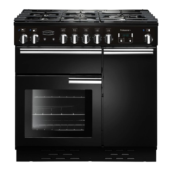
2. Cooker Overview DocNo.020-0006 - Overview - 90DF - Prof+ Fig.2-1 The 90 gas cooker (Fig.2-1) has the following features: Fig.2-2 ArtNo.270-0001 5 hotplate burners including a wok burner Proplus control to high A control panel A glide-out grill Main Autogas oven Tall fan oven Hotplate Burners The drawing by each of the central knobs indicates which... -
Page 8: Wok Burner
If, when you let go of the control knob, the burner goes out, Fig.2-3 then the FSD has not been bypassed. Turn the control knob ArtNo.270-0003 to the ‘OFF’ position and wait for one minute before you try Proplus control to low again, this time making sure to hold in the control knob for slightly longer. -
Page 9: The Wok Cradle (Optional Extra)
The Wok Cradle (optional extra) Fig.2-9 The wok cradle is designed to t a Professional 35cm wok. If you use a di erent wok, make sure that it ts the cradle. Woks vary very widely in size and shape. It is important that the wok sits down on the pan support –... -
Page 10: The Glide-Out Grill
The Glide-out Grill Fig.2-15 Open the door and pull the grill pan carriage forward using the handle (Fig.2-15). The burner does not glow red when in use; food cooks from the heat of the ame. The rst time you light the grill there may be a little smoke given o –... -
Page 11: The Ovens
The Ovens ArtNo.323-0003 Bray gas oven burner flame Fig.2-19 The clock must be set to the time of day before the left- hand oven will work. See the following section on ‘The Clock’ for instructions on setting the time of day. References to ‘left-hand’... -
Page 12: The Fan Oven
Should further browning be necessary, uncover the meat and Fig.2-23 increase the temperature to gas mark 4 for a short period. ArtNo.270-0007 Proplus gas oven control @ 9 Cut root vegetables into small pieces unless cooking whole, e.g. jacket potatoes. Cover dishes tightly with a lid or foil to prevent evaporation and transfer of avour. -
Page 13: The Clock
The Clock Fig.2-27 ArtNo.300-0004 2-button clock annotated You can use the timer (Fig.2-27) to turn the left-hand oven on and o . The clock must be set to the time of day before the ovens will work. Setting the Time of Day When the clock is rst connected, the display ashes ( 0.00 ) ... -
Page 14: Key Lock
To Start and then Stop the Oven Using the Fig.2-32 Fig.2-33 Timer ArtNo.301-0009 2BC ArtNo.301-0010 2BC Before you set the clock, decide on both the ‘cook time’ and Setting the cooking timer Setting the cooking time the ‘stop time’. You cannot set a start time directly – this is set automatically by a combination of the ‘cook time’... -
Page 15: Accessories
Accessories Fig.2-41 Fig.2-42 Oven Shelves – Left-hand (Main) Oven In addition to the at shelves, the cooker is supplied with a drop shelf (Fig.2-40). The drop shelf increases the possibilities for oven shelf spacing. The oven shelves can be easily removed and re tted. ArtNo.320-0011 Removing the shelf 1 ArtNo.320-0012 Removing the shelf 2 Pull the shelf forward until the back of the shelf is stopped by... -
Page 16: Cooking Tips
3. Cooking Tips Tips on Cooking with the Timer General Oven Tips If you want to cook more than one dish, choose dishes that The wire shelves should always be pushed rmly to the back require approximately the same cooking time. However, of the oven. -
Page 17: Cooking Table
4. Cooking Table The oven control settings and cooking times given in the table below are intended to be used AS A GUIDE ONLY. Individual tastes may require the temperature to be altered to provide a preferred result. ArtNo.050-0019 - Albertine SC - Shelf position Food is cooked at lower temperature in a fan oven than in a conventional oven. -
Page 18: Cleaning Your Cooker
5. Cleaning Your Cooker Essential Information Fig.5-1 Isolate the electricity supply before carrying out any thorough cleaning. Allow the cooker to cool. NEVER use paint solvents, washing soda, caustic cleaners, biological powders, bleach, chlorine based bleach cleaners, coarse abrasives or salt. DO NOT mix di erent cleaning products –... -
Page 19: Glide-Out Grill
Glide-out Grill Fig.5-5 Before you remove any of the grill parts for cleaning. make sure that they are cool, or use oven gloves. The face of the grill burner will darken with use – this is perfectly normal. Any fat or grease will burn o . Do not try to clean it –... -
Page 20: Ovens
Glass Fronted Door Panels Fig.5-10 The oven door front panels can be taken o so that the glass panels can be cleaned. Move the cooker forward to gain access to the sides (see the ‘Moving the Cooker’ section under ‘Installation’). Open the oven door slightly and remove the front panel xing screws from the door sides, two each side (Fig.5-10). -
Page 21: The Tall Oven
The Tall Oven Fig.5-15 To clean the oven sides, slide out the shelves, unhook the supports from the oven sides, and lift out (Fig.5-15). Cleaning Table Cleaners listed (Table 5-1) are available from supermarkets or ArtNo.320-0022 Tall oven side support electrical retailers as stated. -
Page 22: Troubleshooting
6. Troubleshooting What cleaning materials are recommended for the The knobs get hot when I use the oven or the grill. Can I cooker? avoid this? See the ‘Cleaning’ section for recommended cleaning Yes, this is caused by heat rising from the oven or the materials. - Page 23 Oven not coming on Fig.6-1 Is the power on? Is the clock illuminated? If not, there may be something wrong with the power supply. Is the cooker supply on at the isolator switch? ArtNo.324-0005 Oven light bulb Has the time of day been set? Is the key symbol [] showing in the display to signify that the oven is locked? See the ‘Clock’...
-
Page 24: Installation
INSTALLATION Check the appliance is electrically safe and gas sound when you have nished. 7. Installation Dear Installer In the UK the cooker must be installed in accordance with: Before you start your installation, please complete the details below, so that, if your customer has a problem relating to •... -
Page 25: Location Of Cooker
INSTALLATION Check the appliance is electrically safe and gas sound when you have nished. Location of Cooker Checking the Parts: The cooker may be installed in a kitchen/kitchen diner but 3 pan supports Plinth NOT in a room containing a bath or shower. This appliance is designed for domestic cooking only. -
Page 26: Positioning The Cooker
INSTALLATION Check the appliance is electrically safe and gas sound when you have nished. Positioning the Cooker ArtNo.090-0009 - 90 2BC cooker min spacings Fig.7-1 Fig.7-1 and Fig.7-2 show the minimum recommended distance from the cooker to nearby surfaces. 75 mm 75 mm 650 mm The cooker should not be placed on a base. -
Page 27: Completing The Move
INSTALLATION Check the appliance is electrically safe and gas sound when you have nished. Lowering the Two Rear Rollers Fig.7-5 To adjust the height of the rear of the cooker, rst t a 13 mm spanner or socket wrench onto the hexagonal adjusting nut (Fig.7-5). -
Page 28: Levelling
INSTALLATION Check the appliance is electrically safe and gas sound when you have nished. Levelling Fig.7-10 You are recommended to use a spirit level on a shelf in one of the ovens to check for level. Place the cooker in its intended position, taking care not to twist it within the gap between the kitchen units as damage may occur to the cooker or the units. -
Page 29: Electrical Connection
INSTALLATION Check the appliance is electrically safe and gas sound when you have nished. Pressure Testing Fig.7-11 The gas pressure can be measured at one of the hotplate Earth: to the burner injectors (not the wok burner). terminal marked E, coloured Green/Yellow Lift o a burner head. -
Page 30: Final Checks
INSTALLATION Check the appliance is electrically safe and gas sound when you have nished. Final Checks Fig.7-12 Hotplate Check Check each burner in turn (refer to the ‘Hotplate Burners’ section at the front of the instructions). Grill Check Turn on the grill and check that the grill heats up. Oven Check Set the clock as described earlier in the instructions, and then turn on the ovens. -
Page 31: Circuit Diagram
8. Circuit Diagram Reign The connections shown in the circuit diagram are for single-phase. The ratings are for 230 V 50 Hz. Code Description Code Description Code Colour Right-hand fan oven thermostat Ignition switch Blue Right-hand fan oven control Ignition spark generator Brown Right-hand fan oven element Main oven light switch... -
Page 32: Technical Data
9. Technical Data ArtNo.105-0008 - Technical data - 90 induction - Elan THIS COOKER IS DESIGNED FOR USE ON EITHER: • Natural gas (Cat I 2H ) at 20 mbar or • LP gas (Cat I 3+ ) Butane 29 mbar / Propane 37 mbar NOTE: The natural gas and LP gas versions of these cookers are di erent models and CANNOT be converted from one gas family to the other. - Page 33 Notes...
- Page 34 Notes...
- Page 35 Gas Safe registered engineer for gas appliances or an approved electrician for electrical models. CONSUMER SERVICE For a competitive quote and to arrange for a Rangemaster approved If you have any product enquiries, or in the event of a problem engineer to attend, call Consumer Services on: 0870 7895107.
- Page 36 Registered in England and Wales. Registration No. 354715 Registered O ce: Juno Drive, Leamington Spa, Warwickshire, CV31 3RG Rangemaster continuously seeks improvements in speci cation, design and production of products and thus, alterations take place periodically. Whilst every e ort is made to produce up-to-date literature, this booklet should not be regarded as an infallible guide to...