
Related Manuals for Cebora SPOT 3500


Summary of Contents for Cebora SPOT 3500
- Page 1 CEBORA S.p.A. SPOT 3500 POWER SOURCE art. 2150 SERVICE MANUAL 3.302.047 21/12/00...
-
Page 2: Table Of Contents
CEBORA S.p.A. CONTENTS - GENERAL INFORMATION - Introduction. - General service policy. - Safety information. - Electromagnetic compatibility. - SYSTEM DESCRIPTION - Introduction. - Technical specifications. - Description of power source art. 2150. - MAINTENANCE - Periodic inspection, cleaning. - Sequence of operations (fig. 3.2.1). -
Page 3: General Information
It is forbidden to attempt to repair damaged electronic boards or modules; replace them with original Cebora spare parts. 1.3 - Safety information. The safety notes provided in this manual are an integral part of those given in the Instruction Manual. -
Page 4: System Description
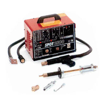
2 - SYSTEM DESCRIPTION 2.1 - Introduction. The SPOT 3500 is a multi-function system for welding, spot-welding, warming and rectifying auto body metal. It is made up of an electronic power source (art. 2150), and a set of accessories to adapt to various applications and tasks (see list in Sales Catalogue). - Page 5 CEBORA S.p.A. the previous time, before the pause. This generating cycle is automatically repeated as long as the start button is held down. In the third instance, the power source delivers an output voltage adjustable via potentiometer (3) on the front panel, without any time limit, for as long as the start button is held down. In this case the output voltage is adjusted by partializing the waveform of the mains voltage applied to the primary circuit of the transformer (26).
-
Page 6: Maintenance
CEBORA S.p.A. 3 - MAINTENANCE WARNINGS ANY INTERNAL INSPECTIONS OR REPAIRS MUST BE CARRIED OUT BY QUALIFIED PERSONNEL. DISCONNECT THE POWER SOURCE FROM THE MAINS BEFORE PERFORMING MAINTENANCE. 3.1 - Periodic inspection, cleaning. Periodically remove any dirt or dust from the air vents to ensure smooth air flow, and thus adequate cooling of the internal parts of the power source. -
Page 7: Starting The Power Source
CEBORA S.p.A. 3.2.2 - Starting the power source. System shut off and disconnected from the mains. Connect the cable with the gun at the power source output (9). Connect the start signal cable of the gun to the connector (10). -
Page 8: Troubleshooting
CEBORA S.p.A. 3.3 - Troubleshooting. WARNINGS ANY INTERNAL INSPECTIONS OR REPAIRS MUST BE CARRIED OUT BY QUALIFIED PERSONNEL. BEFORE REMOVING THE PROTECTIVE GUARDS AND ACCESSING INTERNAL PARTS, DISCONNECT THE POWER SOURCE FROM THE MAINS. NOTE Items in boldface describe problems that may occur on the machine (symptoms). - Page 9 CEBORA S.p.A. CONTROL BOARD (27) POWER SUPPLY TEST. Control board (27), connector CN4, terminals 1 and 5 = 380/415/440 Vac, with switch (5) closed, for machines with this supply voltage. Control board (27), connector CN4, terminals 3 and 5 = 220/230/240 Vac, with switch (5) closed, for machines with this supply voltage.
-
Page 10: Power Source Powered, The Start Button Produces No Effect (Temperature Check)
CEBORA S.p.A. 3.3.2 - Power source powered, the start button produces no effect (temperature check). GUN THERMOSTAT TEST. Control board (27), connector CN1, terminals 2 (+) and 4 (-) = 0 Vdc, contact closed, led (4) off, with appropriate temperature (approximately +17 Vdc, contact open, led (4) lit, with temperature beyond limits, or connector (10) disconnected). -
Page 11: In Open Circuit Operation, The Output Voltage Is Not Regular
CEBORA S.p.A. 3.3.3 - In open circuit operation, the output voltage is not regular. OPEN CIRCUIT OUTPUT VOLTAGE TEST IN MANUAL MODE. Potentiometer (3) Output voltage Waveform position at minimum Fig. 5.2.2 at maximum Fig. 5.2.3 Switch (1) in manual mode (lever to the right), power source output terminals = voltage values and waveforms as in the table, with start button pressed. -
Page 12: In Resistive Load Operation, The Output Voltage Is Not Regular
CEBORA S.p.A. 3.3.4 - In resistive load operation, the output voltage is not regular. NOTE For the following tests use a resistive load capable of circulating a current greater than 100 Aac, for example 0.02 ohm, and capable of supporting the consequent current, considering that the rated open-circuit output voltage is approximately 7 Vac. - Page 13 CEBORA S.p.A. AUTOMATIC SINGLE STROKE OPERATING MODE TEST. Switch (1) in automatic mode (lever to the left), switch (11) in single stroke mode (lever up), power source output terminals = waveform as in fig. 5.2.5, each time the start button is pressed.
-
Page 14: In Actual Working Conditions (Thus With High Currents), The Welding Quality Is Not Satisfactory
CEBORA S.p.A. 3.3.5 - In actual working conditions (thus with high currents), the welding quality is not satisfactory. NOTE In actual working conditions, thus with high currents, the welding quality may not be satisfactory even if the “no-load operating test” par. 3.3.3 and “resistive load operating test” par. 3.3.4 were successful. -
Page 15: Components List
CEBORA S.p.A. 4 - COMPONENTS LIST 4.1 - Power source art. 2150 : see file ESP2150.pdf enclosed at the end of the manual. 4.2 - Components table: see file ESP2150.pdf enclosed at the end of the manual. 4.3 - Spare parts list. -
Page 16: Electrical Diagrams
CEBORA S.p.A. 5 - ELECTRICAL DIAGRAMS 5.1 - Power source art. 2150: see file SCHE2150.pdf enclosed at the end of the manual. 5.2 - Waveforms. 5.2.1 - Output voltage, static switch (14) upon engagement (par. 3.3.1). 5.2.2 - Minimum output voltage, manual mode (par. 3.3.3, 3.3.4). -
Page 17: Output Voltage, Pulse Train Mode (Par. 3.3.3, 3.3.4)
CEBORA S.p.A. 5.2.4 - Output voltage, pulse train mode (par. 3.3.3, 3.3.4). 5.2.5 - Output voltage, single stroke mode (par. 3.3.3, 3.3.4). 5.2.6 - “Current presence” signal of the current transducer (28) (par. 3.3.4, 3.3.5). 3.302.047 21/12/00... -
Page 18: Control Board (27) Code 5.600.857
CEBORA S.p.A. 5.3 - Control board (27) code 5.600.857. 5.3.1 - Topographical drawing. 5.3.2 - Connector table. Conn. Terminals Function start signal input (from gun button). +17 Vdc shared output for gun start button and thermostat. gun temperature input signal (from thermostat).