
Related Manuals for Cebora POWER SPOT 5600


Summary of Contents for Cebora POWER SPOT 5600
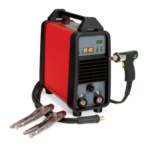
- Page 1 CEBORA S.p.A. POWER SPOT 5600 POWER SOURCE art. 2154 SERVICE MANUAL 3.302.311 23/01/2015...
-
Page 2: Table Of Contents
CEBORA S.p.A. CONTENTS - GENERAL INFORMATION.......................... 3 - Introduction..............................3 - General service policy..........................3 - Safety information............................3 - Electromagnetic compatibility........................3 - SYSTEM DESCRIPTION..........................4 - Introduction..............................4 - Technical specifications..........................4 - Description of power source art. -
Page 3: General Information
It is forbidden to attempt to repair damaged electronic boards or modules; replace them with original Cebora spare parts. 1.3 - Safety information. The safety notes provided in this manual are an integral part of those given in the Instructions Manual. -
Page 4: System Description
2 - SYSTEM DESCRIPTION. 2.1 - Introduction. The POWER SPOT 5600 is a system for welding ferrous and non-ferrous threaded stud bolts or rivets, on various types of sheet metal. It is made up of an electronic power source (art. 2154), and a set of accessories to adapt to various applications and tasks (see Sales Catalogue). - Page 5 CEBORA S.p.A. reached. Normally the programmed voltage that appears upon start-up matches the voltage used the last time welding was performed. This voltage may be changed using the keys on the control panel. If the accessory (gun) connected to the connector (H) changes, the programmed voltage becomes the standard voltage for the connected accessory.
-
Page 6: Maintenance
CEBORA S.p.A. 3 - MAINTENANCE. WARNINGS ANY INTERNAL INSPECTIONS OR REPAIRS MUST BE CARRIED OUT BY QUALIFIED PERSONNEL. BEFORE BEGINNING MAINTENANCE OPERATIONS, UNPLUG THE MACHINE FROM THE MAINS AND WAIT FOR THE INTERNAL CAPACITORS TO DISCHARGE. MEASURE THE VOLTAGE ON THE DC-CAPACITORS (24) EVERY TIME YOU... -
Page 7: Starting The Power Source
CEBORA S.p.A. NOTE Operations preceded by this symbol refer to operator actions. ♦ Operations preceded by this symbol refer to machine responses that must occur following an operator action. 3.2.2 - Starting the power source. System shut off and unplugged from the mains. - Page 8 CEBORA S.p.A. Insert a rivet in the mandrel of the gun and press the tip of the rivet against the surface of the sheet metal to which it is to be welded; press the gun start trigger. ♦ Current output is activated for a few tenths of a second, during which time the rivet is welded to the sheet metal.
-
Page 9: Troubleshooting
CEBORA S.p.A. 3.3 - Troubleshooting. WARNINGS ANY INTERNAL INSPECTIONS OR REPAIRS MUST BE CARRIED OUT BY QUALIFIED PERSONNEL. BEFORE BEGINNING MAINTENANCE OPERATIONS, UNPLUG THE MACHINE FROM THE MAINS AND WAIT FOR THE INTERNAL CAPACITORS TO DISCHARGE. MEASURE THE VOLTAGE ON THE DC-CAPACITORS (24) EVERY TIME YOU... - Page 10 CEBORA S.p.A. SERVICES POWER SUPPLY TEST. Power board (12), rectifier bridge W1, negative terminal (-) and diode D2 cathode (+) = +25 Vdc, with switch (21) closed and mains voltage 230 Vac. Correct? ♦ Check the wiring between CN3 of power board (12) and transformer (31).
-
Page 11: Power Source Powered, Fan (34) Stopped
CEBORA S.p.A. 3.3.2 - Power source powered, fan (34) stopped. FAN TEST. Fast-on terminals fan (34) = 115 Vac (with mains 115 or 230 Vac). Correct? ♦ Make sure that there are no mechanical impediments blocking the fan. ♦ Replace the fan (34). -
Page 12: In Open Circuit Operation, The Voltage At The Dc-Capacitors (24) Is Not Regular
CEBORA S.p.A. 3.3.4 - In open circuit operation, the voltage at the DC-capacitors (24) is not regular. NOTE To check the open circuit operation of the power source, you must measure the output voltage directly on the DC-capacitors (24), since the output terminals (F) and (G) of the power source are connected to this potential only at the moment of welding. -
Page 13: In Resistive Load Operation, The Output Voltage Is Not Regular
CEBORA S.p.A. 3.3.5 - In resistive load operation, the output voltage is not regular. NOTE For the following test use a resistive load capable of circulating a current greater than 100 Adc, at a maximum voltage of 210 Vdc (for example 0.5 ohm). -
Page 14: In Actual Working Conditions (Thus With High Currents), The Welding Quality Is Not Satisfactory
CEBORA S.p.A. 3.3.6 - In actual working conditions (thus with high currents), the welding quality is not satisfactory. In actual working conditions, thus with high currents, the welding quality may not be satisfactory even if the “no-load operating test” par. 3.3.4 and “resistive load operating test” par. -
Page 15: Error Codes
CEBORA S.p.A. 3.4 - Error codes. 3.4.1 - E1 - Transformer (31) temperature above limits. The power source delivers no current, but the fan continues running; we therefore recommend leaving the power source powered to ensure rapid cooling. This is reset automatically when the temperature returns within the allowed limits. -
Page 16: Components List
CEBORA S.p.A. 4 - COMPONENTS LIST. 4.1 - Power source parts drawing. 3.302.311 23/01/2015... -
Page 17: Gun Parts Drawing
CEBORA S.p.A. 4.2 - Gun parts drawing. 3.302.311 23/01/2015... -
Page 18: Parts List
CEBORA S.p.A. 4.3 - Parts list. 3.302.311 23/01/2015... -
Page 19: Electrical Diagrams
CEBORA S.p.A. 5 - ELECTRICAL DIAGRAMS. 5.1 - Power source art. 2154. 3.302.311 23/01/2015... -
Page 20: Waveforms
CEBORA S.p.A. 5.2 - Waveforms. 5.2.1 - Output voltage upon scr (3) engagement (par. 3.3.5). 3.302.311 23/01/2015... -
Page 21: Power Board (12) Code 5.602.169
CEBORA S.p.A. 5.3 - Power board (12) code 5.602.169. 5.3.1 - Topographical drawing. 3.302.311 23/01/2015... - Page 22 CEBORA S.p.A. 5.3.2 - Connector table. Connector Terminals Function input earth connection. 2 - 3 mains power supply input (115 / 230 Vac). 1(+) – 2(-) scr (3) gate command output. output voltage signal input. 5(+) – 6(-) voltage output for discharge resistor (7).
-
Page 23: Control Board (2) Code 5.602.168
CEBORA S.p.A. 5.4 - Control board (2) code 5.602.168. 5.4.1 - Topographical drawing. 5.4.2 - Connector table. Connector Terminals Function shared input for signals from outside. temperature signal input from thermostat on transformer (31). start signal input from gun button. - Page 24 CEBORA S.p.A. CEBORA S.p.A. Via Andrea Costa n° 24 – 40057 Cadriano di Granarolo – Bologna – Italy Tel. +39 051765000 – Telefax: +39 051765222 http://www.cebora.it – E-Mail: cebora@cebora.it 3.302.311 23/01/2015...