Powermatic 72A Instruction Manual & Parts List
14" tilting arbor saw
Hide thumbs
Also See for 72A:
- Maintenance instructions manual (28 pages) ,
- Instruction manual and parts list (28 pages) ,
- Instruction manual & parts list (28 pages)

Related Manuals for Powermatic 72A


Summary of Contents for Powermatic 72A
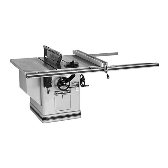
- Page 1 14" TILTING ARBOR SAW Model 72A Instruction Manual & Parts List M-0460207 shown with optional mitre gauge (800) 274-6848 www.powermatic.com...
-
Page 2: More Information
This manual has been prepared for the owner and operators of a Powermatic Model 72A Table Saw. Its purpose, aside from machine operation, is to promote safety through the use of ac- cepted correct operating and maintenance procedures. Completely read the safety and mainte- nance instructions before operating or servicing the machine. -
Page 3: Table Of Contents
TABLE OF CONTENTS Safety Rules ............................4-5 Safety Decals ............................6 Specifications ............................7 Receiving the Saw ..........................8 Installation and Assembly ........................8 Mounting Extension Wings ......................9 Installing Blade..........................9 Mounting Rails & Accu-Fence ..................... 10 Optional Wood Extension Table ....................10 Splitter and Guard Assembly ....................... -
Page 4: Safety Rules
Make certain the work area is well lighted and that a proper exhaust system is used to minimize dust. Powermatic recommends the use of anti-skid floor strips on the floor area where the operator normally stands and that each machine’s work area be marked off. Provide adequate work space around the machine. - Page 5 Misuse. Do not use this Powermatic table saw for other than its intended use. If used for other purposes, Powermatic disclaims any real or implied warranty and holds itself harmless for any injury or damage which may result from that use.
-
Page 6: Safety Decals
SAFETY Familiarize yourself with the location of these safety decals on your table saw. 3408257 FIGURE 1... -
Page 7: Specifications
SPECIFICATIONS: Model 72A Tilting Arbor Saw Table size with standard extensions ..................... 38" W x 48" L Table size with special extensions ....................38" W x 73" L Table size without extensions ....................... 38" W x 26" L Table height ..............................35"... -
Page 8: Receiving The Saw
RECEIVING THE SAW Open shipping container and all separate cartons con- taining rails and accessories. Report any damage immediately to your distributor. Read the instruction manual thoroughly for assembly, alignment, mainte- nance and safety instructions. Box contents: Box 1: table saw, extension wings, mitre gauge, manual Box 2: splitter and guard assembly, splitter support shaft, arbor wrench... -
Page 9: Mounting Extension Wings
MOUNTING EXTENSION WINGS Mount the cast iron extension wings using six 1/2-13 x 1-1/4 hex head screws and six 1/2 lock wash- ers. (These are shipped already inserted into the holes.) See Figure 2. Have an assistant hold the wing up to the table, and insert the screws and washers. -
Page 10: Mounting Rails & Accu-Fence
MOUNTING RAILS & ACCU-FENCE With the extension wings properly aligned, the rail and fence assembly can now be mounted to the saw. Consult the separate Accu-Fence manual for instruc- tions. OPTIONAL WOOD EXTENSION TABLE For instructions on mounting the accessory wood ex- tension table, or router table, consult your Accu-Fence manual. -
Page 11: Electrical Connections
ELECTRICAL CONNECTIONS WARNING: All electrical connections should be done by a qualified electrician. Failure to comply may result in serious injury. The machine must be properly grounded. Consult the electrical schematics on pages 34-36 for proper wiring of the table saw. ADJUSTMENTS FIGURE 10 CAUTION: Disconnect machine from... -
Page 12: Tilt Stop Adjustment
TILT STOP ADJUSTMENT Using a combination square, check the 90 degree (zero) and 45 degree stops as shown in Figure 14. Adjust stop positions if required, using the stop screws as shown. Check the accuracy of the pointer at 90 degrees (zero) and readjust if required. -
Page 13: Splitter Alignment
SPLITTER ALIGNMENT One of the most critical adjustments to help avoid kick- back is the splitter adjustment. It should be checked and re-adjusted, if required, after each blade change. Lift the mitre gauge bar slightly out of its slot. Place a combination square against the side of the raised up miter gauge bar and slide the scale against the top of the blade tooth and against the splitter as shown in Figure 17. -
Page 14: Tilting Mechanism
If the saw arm has been relocated, the table may have to be realigned so as to provide clearance between the saw blade and table insert slot. The splitter will also have to be realigned. NOTE: The saw arm setscrew must be tight to avoid the possibility of movement which could cause the blade to hit the insert. -
Page 15: Operating Instructions
OPERATING INSTRUCTIONS FOR TABLE SAWS (NOTE: Your table saw may not resemble exactly the machine shown in these photos, but the proce- dures will be identical.) Familiarize yourself with the location and opera- tion of all controls and adjustments and the use of accessories such as the mitre gauge and rip fence. -
Page 16: Rip Sawing
- Where possible, keep your face and body out of line with potential kickbacks including when starting or stopping the machine. Dull, badly set, improper, or improperly filed cut- ting tools and cutting tools with gum or resin adher- ing to them can cause accidents. Never use a cracked saw blade. - Page 17 Always use the saw guard, splitter and anti-kick- back pawls. Make sure the splitter is properly aligned. When wood is cut along the grain, the kerf tends to close and bind on the blade and kickbacks can oc- cur. NOTE: A caution decal is installed on the guard and splitter assembly warning of the hazard of misalign- ment.
-
Page 18: Resawing
RESAWING Resawing is a ripping operation in which thick boards are cut into thinner ones. Narrow boards up to 3" can be resawed in one pass. Wider boards up to 6" must be resawed in two passes. In resawing wider boards, adjust the blade height so as to overlap the two cuts by 1/2"... -
Page 19: Bevel & Mitre Operations
Stop rods can be used in the holes provided in the mitre gauge for repetitive work of equal length. Do not use a stop rod on the free end of a workpiece. It should be used on the side of the mitre gauge oppo- site the saw blade. -
Page 20: Safety Devices
The guard, splitter, and anti-kickback pawls supplied with the saw should be used for all cutting operations where they can be used. When performing opera- tions where the guard can not be used, as in some dadoing operations, alternative safety precautions should be taken. - Page 21 FIGURE 37 FIGURE 38...
-
Page 22: Trouble-Shooting
Trouble-Shooting for Model 72A Table Saw PROBLEM POSSIBLE CAUSE SOLUTION [page #] Excessive Vibration. 1. Tilt or raising clamp knobs not tightened. 1. Tighten knobs. [11] 2. Blade out of balance. 2. Change blade. [9] 3. Bad motor. 3. Replace motor. -
Page 23: Optional Accessories
OPTIONAL ACCESSORIES 2195043 Accu-Fence system, 50" 2195048 Accu-Fence assembly only 2250154 Blade guard and splitter assembly 2328023 Table insert 2328024 Dado insert 2389002 Special cast iron extensoin wing kit 2402006 Accu-Fence, side panel replacement kit 2440020 Accu-Fence, rear-lock assembly 2471015 Mitre gauge 6284600 Tenoning jig... -
Page 24: Parts Lists & Exploded Views: Mitre Gauge Assembly
PARTS LIST: Mitre Gauge Assembly 2471015 Part No. Description Quantity 2471015 Mitre Gauge Assembly (Items 1 thru 15) ..............1 3044053 Mitre Gauge Bar ...................... 1 3230038 Mitre Gauge ......................1 3604035 Mitre Gauge Pointer ....................1 3585221 Stop Pin ........................1 3841202 Mitre Gauge Bar Washer .................. -
Page 25: Table Extensions (Optional Accessory)
PARTS LIST: Table Extensions (Optional Accessory - 72A) 2389002 Part No. Description Quantity 2423001 Extension Leg Assembly (Items 3 thru 9) 3186004 11" Square End Extension Table ................1 3186006 25" Round End Extension Table ................1 2423001 Inner Weldment Leg Assembly ................1 3186009 Outer Leg Extension .................... -
Page 26: Stand Assembly
PARTS LIST: Stand Assembly (Model 72A) Part No. Description Quantity 2104031 Motor Cover......................1 2759040 Stand Assembly (Weldment) ................... 1 6440003 Door Latch ......................1 3136018 Dust Removal Door ....................1 3186005 11" Round Extension ....................2 2328023 Insert Assembly (Items 8 & 20) ................1 3328073 Table Insert ...................... -
Page 27: Stand Assembly
Stand Assembly (Model 72A) -
Page 28: Arbor Assembly
PARTS LIST: Arbor (Model 72A) Part No. Description Quantity 3025264 Bearing Arm ......................1 6716003 Socket Set Screw, 3/8-16 X 3/8................1 3773325 Stud, 1/2-13 X 2-5/8 Double End ................1 6716006 Socket Set Screw, 3/8-16 X 1-1/4 ................1 6716081 Square Head Set Screw .................. - Page 29 ARBOR (Model 72A)
-
Page 30: Trunnion Assembly
PARTS LIST: Trunnion (Model 72A) Part No. Description Quantity 2271008 Handwheel Assembly, 8" Diameter (Items 1 & 3) ............. 1 6350032 Handle Assembly ....................1 3271039 Handwheel, 8" Diameter ..................1 2440009 Saw Raising & Tilting Cup Point Lock Assembly (Items 4, 5, 37) ......1 3583011 Locking Pin ...................... - Page 31 Trunnion (Model 72A)
-
Page 32: Splitter & Guard Assembly
PARTS LIST: Splitter & Guard Assembly (Model 72A) Part No. Description Quantity 2250154 Splitter & Guard Assembly (Items 1 thru 23)............1 3750010 Splitter ........................1 3044341 Splitter Bar ......................1 6714113 Round Head Machine Screw, 1/4-20 X 1 ..............4 3736012 Spacer ........................ -
Page 33: Splitter & Guard Assembly
Splitter & Guard Assembly (Model 72A) -
Page 34: Electrical Schematics: 5 Hp, 1 Ph, 230V
ELECTRICAL SCHEMATIC - Model 72A... -
Page 35: Hp, 3 Ph, 230V
ELECTRICAL SCHEMATIC - Model 72A... -
Page 36: Hp, 3 Ph, 460V
ELECTRICAL SCHEMATIC - Model 72A... - Page 39 Locating the stock number of the part(s) required from your parts manual will also expedite your order. Phone No.: (800) 274-6848 Fax No. (800) 274-6840 If you are calling from Canada, please call 800-238-4746 E-mail: powermatic@wmhtoolgroup.com Website: www.powermatic.com...
- Page 40 04/03 WMH Tool Group 427 Sanford Road LaVergne, TN 37086 Phone: (800)274-6848 Fax: (800) 274-6840 E-mail: powermatic@wmhtoolgroup.com Website: www.powermatic.com POWERMATIC ALL RIGHTS RESERVED...