Powermatic 64A Operating Instructions And Parts Manual
10” contractor’s tablesaw
Hide thumbs
Also See for 64A:
- Instruction manual (40 pages) ,
- Operating instructions and parts manual (16 pages)
Table of Contents
Advertisement
Quick Links
- 1 Specifications
- 2 Electrical Connections
- 3 Mounting Blade Guard and Splitter
- 4 Blade Adjustment
- 5 Aligning Miter Slot to Blade
- 6 Parts List: Table Saw, Extension Wings and Guard
- 7 Parts List: Motor and Trunnion Assembly
- 8 Motor and Trunnion Assembly
- Download this manual
See also:
Instruction Manual
Operating Instructions and Parts Manual
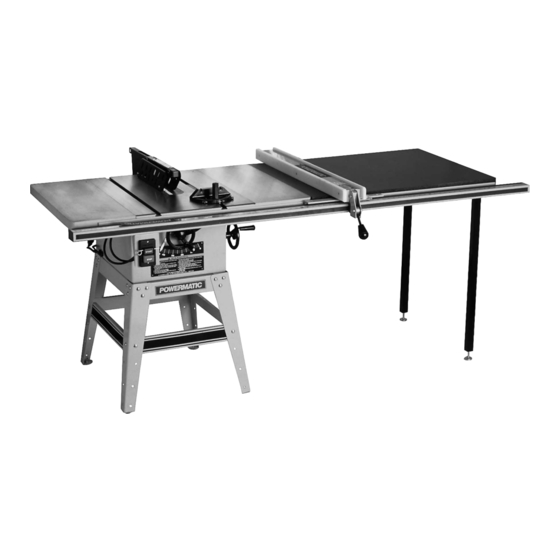
10" Contractor's Tablesaw
Model 64A
Model 1791228K shown (50" rails, wood extension table and legs)
WMH TOOL GROUP, Inc.
2420 Vantage Drive
Elgin, Illinois 60124
Part No. M-0460250
Ph.: 800-274-6848
Revision H 3/08
www.powermatic.com
Copyright © 2008 WMH Tool Group, Inc.
Advertisement
Table of Contents

Related Manuals for Powermatic 64A


Summary of Contents for Powermatic 64A
- Page 1 Operating Instructions and Parts Manual 10” Contractor’s Tablesaw Model 64A Model 1791228K shown (50” rails, wood extension table and legs) WMH TOOL GROUP, Inc. 2420 Vantage Drive Elgin, Illinois 60124 Part No. M-0460250 Ph.: 800-274-6848 Revision H 3/08 www.powermatic.com Copyright © 2008 WMH Tool Group, Inc.
-
Page 2: Warranty And Service
This warranty covers only the initial purchaser of the product. WHAT IS THE PERIOD OF COVERAGE? The general POWERMATIC warranty lasts for the time period specified in the product literature of each product. WHAT IS NOT COVERED? The Five Year Warranty does not cover products used for commercial, industrial or educational purposes. Products with a Five Year Warranty that are used for commercial, industrial or education purposes revert to a One Year Warranty. -
Page 3: Table Of Contents
Table of Contents Warranty and Service ..........................2 Table of Contents ............................ 3 Warning..............................4 Introduction ............................. 6 Specifications ............................6 Electrical Connections ..........................7 Unpacking ............................... 9 Contents of the Shipping Container ...................... 9 Installation and Assembly ........................10 Stand Assembly.......................... -
Page 4: Warning
Warning 1. Read and understand the entire owner’s manual before attempting assembly or operation. 2. Read and understand the warnings posted on the machine and in this manual. Failure to comply with all of these warnings may cause serious injury. 3. -
Page 5: Save These Instructions
19. Be sure the saw blade rotates clockwise when viewed from the motor side (left side) of the machine. 20. Do not attempt to saw boards with loose knots or with nails or other foreign material, on its surface. Do not attempt to saw twisted, warped, bowed or “in wind” stock unless one edge has been jointed for guiding purposes prior to sawing. -
Page 6: Introduction
This manual is provided by WMH Tool Group, Inc. covering the safe operation and maintenance procedures for a Powermatic Model 64A 10” Tablesaw. This manual contains instructions on installation, safety precautions, general operating procedures, maintenance instructions and parts breakdown. This machine has been designed and constructed to provide years of trouble free operation if used in accordance with instructions set forth in this manual. -
Page 7: Electrical Connections
A temporary adapter, which looks like the injury. adapter illustrated in Figure 1(B&C), may be The 64A Tablesaw is equipped with a single used to connect this plug to a 2-pole receptacle phase, 115/230 volt motor. It is factory wired for... - Page 8 230 Volt Conversion If 230V single phase operation is desired, follow these instructions: 1. Disconnect tablesaw from power source. 2. Open the motor junction box, and consult the diagrams affixed to the inside of the junction box cover. These diagrams are also shown in Figures 2 and 3.
-
Page 9: Unpacking
Standard Insert - H Unpacking Dado Insert – J Pulley Cover Seat - K Open shipping container and check for shipping Motor Base Plate – L damage. Report any damage immediately to Pulley Cover - M your distributor and shipping agent. Do not Miter Gauge –... -
Page 10: Installation And Assembly
Installation and Assembly Tools required: Arbor wrench (supplied) 12mm combination wrench (supplied) 3mm and 4mm hex wrenches (supplied) 8, 10, 14, 15, and 19 mm open-end wrenches Cross point and flat head screwdrivers Some assembly tips: 1. A bowl should be used to hold hardware. 2. -
Page 11: Mounting Saw To Stand
2. Attach the four short braces to one set of legs as shown in Figure 6. 3. Complete the stand assembly by attaching the other set of legs as shown in Figure 7. 4. To attach rubber feet to each leg, first use a cross-point screwdriver and screw the 1/4- 20 x 1 pan head screw through the recessed hole of the rubber grommet as shown in... -
Page 12: Handwheels And Lock Knobs
Handwheels and Lock Knobs 1. Attach handwheel knob (A) by inserting screw (B) through hollow knob and into the 3/8" lock nut (C). See Figure 10. Lightly screw assembly into handwheel. 2. Tighten the nut (C) to the handwheel just enough so that there is adequate looseness in the knob (A) to allow free rotation. - Page 13 6. Install motor assembly onto protruding studs at the back of the saw. See Figure 15. 7. Tighten down setscrews in top of cast motor bracket with hex wrench as shown in Figure 8. Use an assistant or get a support block (for example, a 2x4) approximately 21"...
-
Page 14: Mounting Blade Guard And Splitter
Mounting Blade Guard and Splitter 1. Disconnect saw from power source. 2. Attach splitter mounting bracket to saw trunnion using pin, nut and washer as shown in Figure 18. Insert the pin into the trunnion hole until it is flush on the other side, then hold a wrench on the flat of the pin to stabilize while... -
Page 15: Mounting Table Insert
Mounting Table Insert 1. Place the table insert into the table opening. With a straight edge, check to see if the insert is level with the surface of the table. See Figure 22. 2. If the insert is not level, correct it by using the straight edge and turning the four set screws in or out until the insert is flush with the table. -
Page 16: Installing Dust Shroud
Installing Dust Shroud TIP: Since the dust shroud is installed from beneath, aid from a helper to install the screws and tabs will make this task much easier. 1. From under the saw, position the dust shroud at an angle to go through the opening between the stand and the saw. -
Page 17: Dado Insert
Dado Insert Dadoing is cutting a rabbet or a wide groove into the workpiece. The dado insert, shown in Figure 27, is included as standard equipment with your saw. Rotate the set screws as needed to level the dado insert with table surface. Do not use the standard table insert for dadoing operations. -
Page 18: 45 And 90 Degree Positive Stops
45 and 90 Degree Positive Stops Convenient access to these adjustments will be from the back side of the saw. 1. Disconnect machine from power source. 2. Raise the saw blade to its maximum height. 3. Set the blade at 90 degrees to the table by turning the blade tilting handwheel clockwise as far as it will go. -
Page 19: Aligning Splitter To Blade
3. If it does not, loosen lock handle (B - Figure 32). 4. Loosen locknut (E), and adjust the stop screw, (A), so it strikes the stop link (D) when the gauge is at 90 degrees. 5. Retighten both the locknut (E) and lock handle (B). -
Page 20: Basic Saw Operation
Basic Saw Operation 1. Familiarize yourself with the location and operation of all controls and adjustments and the use of the mitre gauge and rip fence. 2. Serious injury can result from kickbacks which occur when a workpiece binds on the saw blade or binds between the saw blade and rip fence or other fixed objects. -
Page 21: Operating Procedures
Check the operation of the anti-kickback pawls before starting a cut. If the pawls do not stop the reverse motion of a workpiece, resharpen all the points. Keep your face and body out of line with potential kickbacks when possible, including when starting or stopping the machine. - Page 22 3. Never rip freehand or use the miter gauge in combination with the fence. Never rip workpieces shorter than the blade diameter without a push stick. Never remove the cutoff piece with the saw blade rotating. 4. Always use the saw guard, splitter and anti- kickback pawls and make sure the splitter is properly aligned.
- Page 23 Resawing 1. Resawing is a ripping operation in which thick boards are cut into thinner ones. Narrow boards up to 3" can be resawn in one pass. Wider boards up to 6" must be resawn in two passes. 2. In resawing wider boards, adjust the blade height so as to overlap the two cuts by 1/2"...
- Page 24 7. Provide auxiliary support for any workpiece which tends to sag and lift up off the table when it extends beyond the table top. 8. Have the blade extend about 1/8" above the top of the workpiece. Exposing the blade above this point can be hazardous.
-
Page 25: Safety Devices
Never use a wedge between arbor collar and saw blade to create a "wobble" dado. Never operate the saw without guard, splitter and anti-kickback pawls for operations where they can be used. Never use a dado head in tilted position. SAFETY DEVICES Feather Board (Figure 46) The Feather Board is to be made of straight... -
Page 26: Maintenance
Push Stick 709721 Featherboard 2042367 Mobile base for Model 64A with 50” Rip Capacity, Ext. Table and Legs 2042370 Mobile base for Model 64A with 30” Rip Capacity, Ext. Table and Legs 2195076K Accu-Fence system, 30” 2195077K Accu-Fence system, 50"... - Page 27 Troubleshooting Trouble Probable Cause Remedy No incoming power. Check all plug connections. Tablesaw will not Fuse blown, or circuit breaker tripped. Replace fuse, or reset circuit breaker. start. Cord damaged. Replace cord. Tilting or Raising lock knobs not Tighten lock knobs on handwheels. tightened.
-
Page 28: Replacement Parts
Replacement parts are listed on the following pages. To order parts or reach our service department, call 1-800-274-6848, Monday through Friday (see our website for business hours, www.powermatic.com). Having the Model Number and Serial Number of your machine available when you call will allow us to... -
Page 29: Parts List: Table Saw, Extension Wings And Guard
Parts List: Table Saw, Extension Wings and Guard Index No. Part No. Description Size 1....6290694....Table Insert ................... 1 1-A ... 6291342....Rubber spacer..................2 2....6290695....Dado Insert.................... 1 4....6290502....Socket Set Screw ..........1/4-20 x 5/16 ....8 5....6290696....Table..................... 1 6.... - Page 30 66..... 6291335....Nut ..............3/16-24....... 2 67..... 6291366....Switch Box .................... 1 68..... 6291367....Switch Bracket..................1 69..... 6291368....Switch ....................1 70..... 6291338....Pan Head Screw ..........3/16-24 x 1-1/2 ... 2 71..... 6291375....Pan Head Screw ..........3/16-24 x 5/8 ....1 77..... 6290672....Splitter Mounting Plate................1 80.....
-
Page 31: Parts List: Stand Assembly
Parts List: Stand Assembly Index No. Part No. Description Size 1....6290646....Leg......................4 2....6290650....Bottom Long Bracket ................2 3....6290648....Bottom Short Bracket................2 4....6290647....Top Short Bracket.................. 2 5....6290649....Top Long Bracket .................. 2 6....6290645....Dust Cover .................... 1 7.... -
Page 32: Parts List: Motor And Trunnion Assembly
Parts List: Motor and Trunnion Assembly Index No. Part No. Description Size 1....6290563....Knob ..................... 2 2....6290565....Handle....................2 3....6290566....Nut, Hex Hd............3/8-16......4 4....6290564....Handwheel .................... 2 5....6290567....Flat Washer............3/8......3 6....6290678....Pointer....................1 7....6290569....Set Screw............1/4-20 x 1/4 ....3 8.... - Page 33 74..... 6291325....Fiber Washer............5/16......2 75..... 6285540....Wing Nut ............5/16-18....... 2 76..... 6290642....Wrench...............#23......1 77..... 6290643....Wrench...............12-14......1 78..... 6290644....Hex Wrench ............3mm......1 79..... 6291361....Hex Head Nut (L.H.Threads) ......5/8-18 UNF....4 81..... 6290641....Screw..............3/8-16 x 2 ....1 83..... 6291362....Link Bar, L.H. Threads................1 84.....
-
Page 34: Motor And Trunnion Assembly
Motor and Trunnion Assembly... - Page 36 WMH Tool Group, Inc. 2420 Vantage Drive Elgin, Illinois 60124 Phone: 800-274-6848 www.powermatic.com www.wmhtoolgroup.com...