
Related Manuals for Powermatic 74A


Summary of Contents for Powermatic 74A
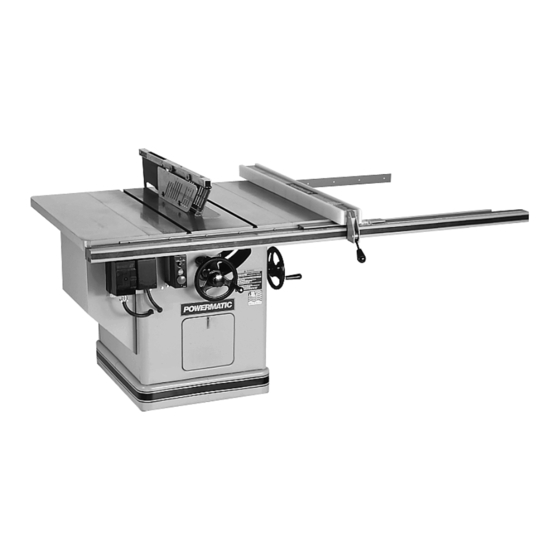
- Page 1 TILTING ARBOR & SCORING SAW Model 74A Instruction Manual & Parts List M-0460208 (800) 274-6848 www.powermatic.com...
-
Page 2: More Information
This manual has been prepared for the owner and operators of a Powermatic Model 74A Tilting Arbor/Scoring Saw. Its purpose, aside from machine operation, is to promote safety through the use of accepted correct operating and maintenance procedures. Completely read the safety and maintenance instructions before operating or servicing the machine. -
Page 3: Table Of Contents
TABLE OF CONTENTS Safety Rules ............................4-5 Safety Decals ............................6 Specifications ............................6 Receiving the Saw ..........................7 Installation & Assembly ......................... 7 Cast Iron Extensions ........................7 Mounting Blade ..........................7 Rails & Accu-Fence ........................7 Splitter & Guard Assembly ......................7 Mitre Gauge .......................... -
Page 4: Safety Rules
Make certain the work area is well lighted and that a proper exhaust system is used to minimize dust. Powermatic recommends the use of anti-skid floor strips on the floor area where the operator normally stands and that each machine’s work area be marked off. Provide adequate work space around the machine. - Page 5 Misuse. Do not use this Powermatic table saw for other than its intended use. If used for other purposes, Powermatic disclaims any real or implied warranty and holds itself harmless for any injury or damage which may result from that use.
-
Page 6: Specifications
SAFETY Familiarize yourself with the location of these safety decals on your table saw. FIGURE 1 SPECIFICATIONS (Model 74A) Table Height ............................35" Table size without extension ..................... 38" W x 26" L Table Size Std. Extension ....................38" W x 48" L Table Size Long Extensions .................... -
Page 7: Receiving The Saw
RECEIVING THE SAW Remove the saw from its shipping carton and check for damage. Report any damage to your distributor immediately. Accessories and rails were shipped in separate cartons. Read the instruction manual thor- oughly for assembly, alignment, maintenance and safety instructions. -
Page 8: Adjustments
ADJUSTMENTS FENCE ALIGNMENT ® See Accu-Fence manual. MITER SLOT ALIGNMENT MITRE GAUGE ADJUSTMENT To check the alignment of the miter slot to the blade, The mitre gauge is equipped with individually adjust- raise the blade to its 0 (90 deg.) position and its maxi- able index stops at 90 degrees and 45 degrees right mum height. -
Page 9: Scoring Blade Belt Tensioning
NOTE: The saw arm setscrew must be tight to avoid the possibility of movement which could cause the blade to hit the insert. FIGURE 9 SCORING BLADE BELT TENSIONING FIGURE 11 The scoring blade belt is tensioned by the weight of the motor. -
Page 10: Insert Adjustment
The scoring blade kerf is adjusted by increasing or TILTING MECHANISM ADJUSTMENT decreasing the number of shims between the two scor- If binding occurs in the tilting mechanism, clean off ing blade halves (the scoring blade actually consists the sawdust and pitch accumulation and re-grease. If of two narrow blades). -
Page 11: Maintenance
so that it tends to angle toward rather than away MAINTENANCE from the saw blade front to back. NOTE: Caution decal on guard and splitter as- Good saw operation requires periodic preventive main- sembly. tenance. Keep the inside of the cabinet and trunnion f. -
Page 12: Rip Sawing
Never rip freehand or use the miter gauge in combi- nation with the fence. Never rip workpieces shorter than the saw blade di- ameter. Never reach behind the blade with either hand to hold down or remove the cutoff piece with the saw blade rotating. -
Page 13: Resawing
For work shorter than 12" or narrower than 6", use a push stick or block to push it through between the fence and the saw blade. Never use the rip fence beyond the point where the carriage is flush with the end of the rails. Have the blade extend about 1/8"... - Page 14 BEVEL & MITER OPERATIONS Crosscuts made at an angle to the edge of the workpiece are called miters. Set the miter gauge A bevel cut is a special type of operation where at the required angle, lock the miter gauge, and make the saw blade is tilted at an angle less than 90 de- the cut the same as a normal crosscut except the grees to the table top.
-
Page 15: Trouble-Shooting
TROUBLE-SHOOTING for 74A Table Saw PROBLEM POSSIBLE CAUSE SOLUTION Excessive Vibration. 1. Tilt or raising clamp knobs not tightened. 1. Tighten knobs. 2. Blade out of balance. 2. Change blade. 3. Bad motor. 3. Replace motor. 4. Loose arbor or motor sheave. -
Page 16: Feather Board Construction
FEATHER BOARD CONSTRUCTION The Feather Board is to be made of straight grain hardwood approximately 1" thick and 4" to 8" wide according to the size of the machine. The length should be developed in accordance with its intended use. Feather Boards can be fastened to the table or rip fence by the use of "C"... -
Page 17: Optional Accessories
OPTIONAL ACCESSORIES 2195043 Accu-Fence and rail system for ripping 50" to right and 12" to left of saw blade 2195048 Accu-Fence assembly only 2250113 Blade guard and splitter assembly 2328023 Table insert 2328024 Dado insert 2389002 Special cast iron extension wing kit 2402006 Accu-Fence, side panel replacement kit 2440020... -
Page 18: Stand Assembly
PARTS LIST: Stand Assembly (Model 74A) Part No. Description Quantity 3104303 Motor Cover......................1 2759042 Stand Assembly (Weldment) ................... 1 2136002 Door Assembly (Items 5 & 6) .................. 1 6440003 Door Latch ......................1 3136018 Dust Removal Door ....................1 3186005 11"... -
Page 19: Stand Assembly
Stand Assembly (Model 74A) - Page 20 PARTS LIST: Arbor (Model 74A) Part No. Description Quantity 2025070 Bearing Arm Assembly .................... 1 3025265 Bearing Arm ......................1 6716003 Socket Set Screw, 3/8-16 X 3/8 ................1 3773325 Stud, 1/2-13 X 2-5/8 Double End ................1 6716006 Socket Set Screw, 3/8-16 X 1-1/4 ................1 6716081 Square Head Set Screw, 3/8-16 x 1-1/2 ..............
- Page 21 PARTS LIST: Arbor (Model 74A) Part No. Description Quantity 6472504 Motor, 7.5 HP, 3 Ph, ....................1 6470506 Scoring Motor, 1/2 HP, 3 Ph, 230/460V ..............1 6470505 Scoring Motor, 1/2 HP, 1 Ph, 230V ................1 6472327 Motor, 5 HP, 3 Ph, 200V ..................1 6716101 Socket Set Screw, 3/8-16 x 1 .................
-
Page 22: Arbor
Arbor (Model 74A) - Page 23 PARTS LIST: Mitre Gauge Assembly (Model 74A) Part No. Description Quantity 2471015 Mitre Gauge Assembly (Items 1 thru 15) ..............1 3044053 Mitre Gauge Bar ...................... 1 3230038 Mitre Gauge ......................1 3604035 Mitre Gauge Pointer ....................1 3761001 Stop Pin ........................1 3841202 Mitre Gauge Bar Washer ..................
- Page 24 PARTS LIST: Trunnion (Model 74A) Part No. Description Quantity 2271008 Handwheel Assembly, 8" Diameter ................1 6350032 Handle Assembly ....................1 3271039 Handwheel, 8" Diameter ..................1 2440009 Saw Raising & Tilting Cup Point Lock Assembly (Items 4 & 5) ........ 1 3583011 Locking Pin ......................
-
Page 25: Trunnion
Trunnion (Model 74A) - Page 26 PARTS LIST: Scoring Assembly (Model 74A) Part No. Description Quantity 2025070 Bearing Arm Assembly .................... 1 2810011 Trunnion Assembly ....................1 3810039 Trunnion Housing ....................1 3025084 Bearing Scoring Arm ....................1 3711008 Pivot Shaft ......................1 6715162 Socket Set Screw, 5/16-18 X 5/16 ................1 6716079 Square Head Set Screw, 3/8-16 x 1 ................
-
Page 27: Scoring Assembly
Scoring Assembly (Model 74A) - Page 28 PARTS LIST: Splitter & Guard Assembly (Model 74A) Part No. Description Quantity 2250154 Splitter & Guard Assembly (Items 1 thru 23) ............1 3750010 Splitter ........................1 3044306 Splitter Bar ......................1 6714113 Round Head Machine Screw, 1/4-20 X 1 ..............4 3736012 Spacer ........................
-
Page 29: Splitter & Guard Assembly
Splitter & Guard Assembly (Model 74A) -
Page 30: Optional Table Extensions
PARTS LIST: Optional Table Extensions (Model 74A) Part No. Description Quantity 2423001 Extension Leg Assembly (Items 3 thru 9) ..............1 3186004 11" Square End Extension Table ................1 3186006 25" Round End Extension Table ................1 2423001 Inner Weldment Leg Assembly ................1 3186009 Outer Leg Extension .................... -
Page 31: Electrical Schematic
ELECTRICAL SCHEMATIC: 74A Scoring Saw SINGLE PHASE MAGNETIC STARTERS Single Phase Controls starter overload motor size contactor relay 3HP- 230V 6816266 6659052 5HP- 230V 6816269 6659053 Three Phase Controls 5HP - 230V 6816266 6659051 5HP - 460V 6816262 6659049 7.5 - 230V... -
Page 32: Electrical Schematics
ELECTRICAL SCHEMATIC 74A Scoring Saw THREE PHASE... - Page 35 Locating the stock number of the part(s) required from your parts manual will also expedite your order. Phone No.: (800) 274-6848 Fax No. (800) 274-6840 If you are calling from Canada, please call 800-238-4746 E-mail: powermatic@wmhtoolgroup.com Website: www.powermatic.com...
- Page 36 06/02 WMH Tool Group P.O. Box 1349 Auburn, WA 98071-1349 Phone: (800) 274-6848 Fax: (800) 274-6840 E-mail: powermatic@wmhtoolgroup.com Website: www.powermatic.com POWERMATIC ALL RIGHTS RESERVED...