Powermatic 66 Operating Instructions And Parts Manual
10-inch table saw
Hide thumbs
Also See for 66:
- Instruction manual & parts list (40 pages) ,
- Maintenance instructions and parts list (25 pages) ,
- Operating instructions manual (18 pages)
Table of Contents
Advertisement
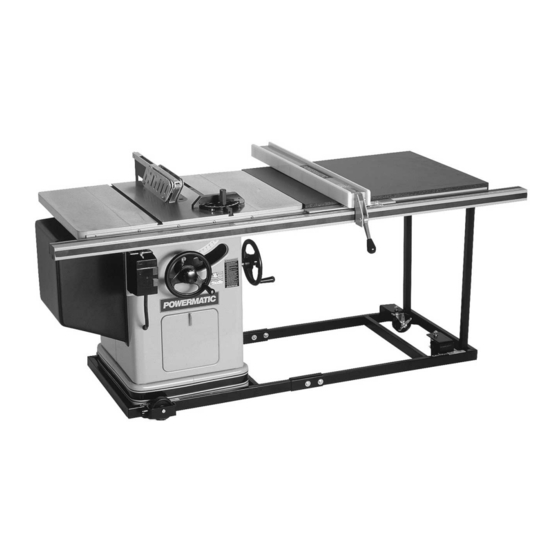
Operating Instructions and Parts Manual
10-inch Table Saw
Model 66
shown with optional extension table and legs,
mobile base, and motor cover
WMH TOOL GROUP
2420 Vantage Drive
Elgin, Illinois 60123
Part No. M-0460231NT
Ph.: 800-274-6848
Revision G 1/05
www.wmhtoolgroup.com
Copyright © WMH Tool Group
Advertisement
Table of Contents

Related Manuals for Powermatic 66


Summary of Contents for Powermatic 66
- Page 1 Operating Instructions and Parts Manual 10-inch Table Saw Model 66 shown with optional extension table and legs, mobile base, and motor cover WMH TOOL GROUP 2420 Vantage Drive Elgin, Illinois 60123 Part No. M-0460231NT Ph.: 800-274-6848 Revision G 1/05 www.wmhtoolgroup.com...
-
Page 2: Warranty And Service
This manual has been prepared for the owner and operators of a Powermatic 66 Table Saw. Its purpose, aside from machine operation, is to promote safety using accepted operating and maintenance procedures. To obtain maximum life and efficiency from your table saw and to aid in using it safely, please read this manual thoroughly and follow the instructions carefully. -
Page 3: Table Of Contents
Table of Contents Warranty and Service ...2 Warning...4 Introduction...6 Specifications ...6 Unpacking ...7 Contents of the Shipping Container ...7 Installation and Assembly ...8 Mounting Extension Wings ...8 Installing Blade...9 Mounting Rails and Accu-Fence Optional Wood Extension Table ...9 Splitter and Guard Assembly ...9 Motor Cover ...10 Grounding Instructions...10 Extension Cords...11... -
Page 4: Warning
5. Do not use this table saw for other than its intended use. If used for other purposes, WMH Tool Group disclaims any real or implied warranty and holds itself harmless from any injury that may result from that use. -
Page 5: Save These Instructions
Make sure the blade is securely locked on the arbor. 28. Keep hands clear of the blade area. Do not reach past the blade to clear parts or scrap with the saw blade running. Never saw freehand. Avoid awkward operations and hand positions where a sudden slip could cause your hand to contact the blade. -
Page 6: Introduction
This manual is provided by WMH Tool Group covering the safe operation and maintenance procedures for a Powermatic Model 66 Table Saw. This manual contains instructions on installation, safety precautions, general operating procedures, maintenance instructions and parts breakdown. This machine has been designed and constructed to provide years of trouble free operation if used in accordance with instructions set forth in this manual. -
Page 7: Unpacking
Report any damage immediately to your distributor and shipping agent. Do not discard any shipping material until the Table Saw is assembled and running properly. Compare the contents of your container with the following parts list to make sure all parts are intact. -
Page 8: Installation And Assembly
(Figure 2) holding the saw to the wood pallet. Carefully slide the saw from the pallet onto the floor. 4. Tilt the saw, and pop off the metal tabs (Figure 2) that secured the saw to the pallet, by pushing down on them with your foot. -
Page 9: Installing Blade
3. Level the extension wing with the saw table across its entire width, using a straight edge and hammer with block of wood (or rubber hammer). See Figure 5. As each area of the wing becomes flush with the table, tighten the screw under that area. -
Page 10: Motor Cover
A power plug is not provided with the Model 66. You may either connect the proper UL/CSA listed plug or “hardwire” the machine directly to your electrical panel provided there is a disconnect near the machine for the operator. -
Page 11: Extension Cords
Make sure the voltage of your power supply matches the specifications on the motor plate of the machine. Extension Cords If an extension cord is necessary, make sure the cord rating is suitable for the amperage listed on the machine's motor plate. An undersize cord will cause a drop in line voltage resulting in loss of power and overheating. -
Page 12: Tilt Stop Adjustment
Figure 17. Re-adjust the stop position as required. Belt Tensioning The saw is equipped with a set of two matched belts. If they should need replacement, replace the complete set. To tension the belts: Loosen the hex screw (A, Figure 18) and nut (B, Figure 18) on the motor bracket. -
Page 13: Splitter Alignment
See Figure 20. Arbor and Arbor Bearing Removal 1. To remove the saw arbor, first remove the fence and rails, then remove the three mounting screws holding the table to the base (see Figure 15). Lift off the table. -
Page 14: Tilting Mechanism Adjustment
If the saw raising arm has been re-located, the table may have to be realigned so as to provide clearance between the saw blade and table insert slot. The splitter will also have to be realigned. NOTE: The saw arm setscrew must be tight to avoid the possibility of movement which could cause the blade to hit the insert. - Page 15 4. Dull, badly set, improper, or improperly filed cutting tools and cutting tools with gum or resin adhering to them can cause accidents. Never use a cracked saw blade. The use of a sharp, well maintained, and correct cutting tool for the operation will help to avoid injuries.
-
Page 16: Rip Sawing
9. Bevel ripping cuts should always be made with the fence on the right side of the saw blade so that the blade tilts away from the fence and minimizes the possibility of the work binding and the resulting kickback. -
Page 17: Resawing
Crosscutting 1. Crosscutting is where the workpiece is fed cross grain into the saw blade using the miter gauge to support and position the workpiece. See Figure 31. Crosscutting should never be done freehand nor should... -
Page 18: Bevel And Miter Operations
Bevel and Miter Operations 1. A bevel cut is a special type of operation where the saw blade is tilted at an angle less than 90 degrees to the table top. See Figure 34. Operations are performed in the... -
Page 19: Dado Cutting
This is very useful for shelving, making joints, tenoning, etc. The guard, splitter, and anti-kickback pawls supplied with the saw should be used for all cutting operations where they can be used. When performing operations where the guard can not be used, as in some dadoing operations, alternative safety precautions should be taken. -
Page 20: Maintenance
To accomplish this, remove the table by removing the three mounting screws (see Figure exposing mechanisms of the saw. After cleaning the tilting and raising worm and worm gear segments and the trunnions, grease these three areas with a good grade non-hardening grease. - Page 21 Figure 40...
-
Page 22: Troubleshooting
Fence misalignment. Cuts not true at 90 or Stop screws not set properly. 45 degrees. Lock knob not released. Tilt or saw raising Worm and worm gear segment caked handwheels difficult with sawdust and pitch. to turn. Worm and worm gear segment out of alignment. -
Page 23: Optional Accessories
Mobile base with 30" fence with Rout-R-Lift. ® and rail system for ripping 50" to right and 12" to left of saw blade. 2195042K Accu-Fence ® - fence assembly only, no rails - for Model 66. 2195079 Accu-Fence ® and rail system for Model 66 w/sliding table. -
Page 24: Parts List: Trunnion Assembly
Parts List: Trunnion Assembly Index No. Part No..2810012... Trunnion Assembly (Items 1 thru 65)..1 ...2271035... Handwheel Assembly (Items 2 thru 7)..2 2...2271036... Handle Assembly (Items 4, 6, 7) ..2 3...3271084... Handwheel ... 8” diameter ... 2 4...3271085... - Page 25 63 ...3810040... Rear Trunnion..1 64 ...6420002... Woodruff Key... #608 ... 3 65 ...3868032... Arbor Wrench ..2 66 ...3700090... Splitter Support Shaft..1 67 ...6716035... Hex Head Screw... 3/8-16 x 1-3/4... 4 68 ...6861300... Lock Washer... 3/8 ... 10 69 ...6516001...
-
Page 26: Trunnion Assembly
Trunnion Assembly... -
Page 27: Parts List: Miter Gauge
Parts List: Miter Gauge Index No. Part No. Description Size ...2471015... Mitre Gauge Assembly (Items 1 Thru 14) ..1 1...3044053... Mitre Gauge Bar ..1 2...3230038... Mitre Gauge..1 3...3604035... Mitre Gauge Pointer..1 4...3585221... Stop Pin..1 5...3841202... -
Page 28: Parts List: Splitter And Guard Assembly
Parts List: Splitter and Guard Assembly Index No. Part No. Description ...2787008... Splitter Rear Support Assembly (Items 1 thru 7) ... 1 1...6715034... Hex Head Cap Screw ... 5/16-18 x 1-1/4 ... 1 2...6861200... Lock Washer... 5/16 ... 1 3...3776050... Splitter Rear Support ..1 4...6572007... -
Page 29: Splitter And Guard Assembly
Splitter and Guard Assembly... -
Page 30: Parts List: Stand Assembly
Parts List: Stand Assembly Index No. Part No. Description 1...6716031... Hex Head Screw... 3/8-16 x 1 ... 9 2...6861300... Lock Washer... 3/8 ... 9 3...3186008... Standard Extension ... 8"... 2 ...2328002... Dado Insert Assembly (Items 4 & 5) ..1 4...6714081... -
Page 31: Stand Assembly
Stand Assembly... -
Page 32: Parts List: Table Extension And Legs (Optional Accessory)
Parts List: Table Extension and Legs (Optional Accessory) Index No. Part No. Description ...2389003... Extension Kit (Items 1 thru 10) ..1 ...2423001... Extension Table Support Leg Assembly (Items 1 thru 8) ... 1 1...2423006... Inner Extension Leg Assembly..1 2...3186009... -
Page 33: Electrical Connections
Electrical Connections... -
Page 37: Maintenance Checklist
Inspect entire machine for loose bolts, nuts, screws. Tighten and replace as necessary. Thoroughly clean trunnion area, removing sawdust and chips with soft bristle brush. Remove pitch from trunnions, quadrant gears, elevating and tilt worm gears, and saw blades using oven cleaner. - Page 38 NOTES...
- Page 40 WMH Tool Group 2420 Vantage Drive Elgin, Illinois 60123 Phone: 800-274-6848 www.wmhtoolgroup.com...