Dell Networking N4000 Series Configuration Manual
Stackable layer 2 and 3 switches
Hide thumbs
Also See for Networking N4000 Series:
- Getting started manual (378 pages) ,
- Configuration manual (17 pages) ,
- Reference manual (2332 pages)

Related Manuals for Dell Networking N4000 Series


Summary of Contents for Dell Networking N4000 Series
-
Page 1: Series Switches
Dell Networking N2000, N3000, and N4000 Series Switches User’s Configuration Guide Regulatory Models: N2024, N2024P, N2038,N2048P, N3024, N3024F, N3024P, N3048, N3048P, N4032, N4032F, N4064, N4064F... - Page 2 Other trademarks and trade names may be used in this publication to refer to either the entities claiming the marks and names or their products. Dell Inc. disclaims any proprietary interest in trademarks and trade names other than its own.
-
Page 3: Table Of Contents
Contents Introduction ..... . . About This Document ....Audience . - Page 4 Single IP Management ....Master Failover with Transparent Transition ..Nonstop Forwarding on the Stack ..Hot Add/Delete and Firmware Synchronization .
- Page 5 Power over Ethernet (PoE) Plus Features ..Power Over Ethernet (PoE) Plus Configuration ....PoE Plus Support .
- Page 6 GARP and GVRP Support ....Voice VLAN ..... Guest VLAN .
- Page 7 ..Hardware Overview ....Dell Networking N2000 Series Switch Hardware . . . N2000 Series Front Panel .
- Page 8 Switches ..... Dell Networking N4000 Series Switch Hardware ......
- Page 9 Using the Device View Switch Locator Feature ..... . . Using the Command-Line Interface ..Accessing the Switch Through the CLI .
- Page 10 What Is Out-of-Band Management and In-Band Management? ....Default Network Information ... . . Configuring Basic Network Information (Web) .
- Page 11 Stacking Overview ....Dell Networking N2000, N3000, and N4000 Stacking Compatibility ....
- Page 12 Managing the Stack (CLI) ....Configuring Stack Member, Stack Port, and NSF Settings ....Viewing and Clearing Stacking and NSF Information .
- Page 13 Authorization Examples ....Local Authorization Example—Direct Login to Privileged EXEC Mode ... TACACS+ Authorization Example—Direct Login to Privileged EXEC Mode .
- Page 14 11 Monitoring and Logging System Information ..... . System Monitoring Overview ... . . What System Information Is Monitored? .
- Page 15 Monitoring System Information and Configuring Logging (CLI) ..... . . Viewing System Information and Enabling the Locator LED ....Running Cable Diagnostics .
- Page 16 Series Only) ....Viewing Slot Information (N4000 Series Only) ......
- Page 17 What Are SNMP Traps? ....Why Is SNMP Needed? ....Default SNMP Values ....Configuring SNMP (Web) .
- Page 18 What Methods Are Supported for File Management? ....What Factors Should Be Considered When Managing Files? ....How Is the Running Configuration Saved? .
- Page 19 How Does USB Auto Configuration Use the Files on the USB Device? ....What Is the Setup File Format? ... What Is the DHCP Auto Configuration Process? .
- Page 20 Default Traffic Monitoring Values ... Monitoring Switch Traffic (Web) ... sFlow Agent Summary ....sFlow Receiver Configuration .
- Page 21 ....How Does iSCSI Optimization Interact With Dell EqualLogic Arrays? ....
- Page 22 18 Configuring Port Characteristics ..Port Overview ..... What Physical Port Characteristics Can Be Configured? .
- Page 23 Port Security (Port-MAC Locking) ..Captive Portal ..... . Captive Portal Overview .
- Page 24 Policy Based Routing ....Overview ..... Limitations .
- Page 25 VLAN Configuration Examples ... . . Configuring VLANs Using Dell OpenManage Administrator ....
- Page 26 Configure the VLANs and Ports on Switch 2 . . . Configuring VLANs Using the CLI ..Configuring a Voice VLAN ... . 22 Configuring the Spanning Tree Protocol .
- Page 27 Configuring Spanning Tree (CLI) ... . . Configuring Global STP Bridge Settings ..Configuring Optional STP Features ..Configuring STP Interface Settings .
- Page 28 LLDP-MED Remote Device Information ..Configuring ISDP and LLDP (CLI) ... Configuring Global ISDP Settings ..Enabling ISDP on a Port .
- Page 29 Configuring Protected Ports ... . Configuring LLPF ....Port-Based Traffic Control Configuration Example .
- Page 30 VLAN Querier Status ....MFDB IGMP Snooping Table ... MLD Snooping General ....MLD Snooping Global Querier Configuration .
- Page 31 What is the Administrator’s Role? ..Default Dot1ag Values ....Configuring Dot1ag (Web) ....Dot1ag Global Configuration .
- Page 32 Default Traffic Snooping and Inspection Values . . . Configuring Traffic Snooping and Inspection (Web) ....DHCP Snooping Configuration ..DHCP Snooping Interface Configuration .
- Page 33 28 Configuring Link Aggregation ..Link Aggregation ..... Overview ..... . Default Link Aggregation Values .
- Page 34 DCB Capability Exchange ....Interoperability with IEEE DCBx ..DCBx and Port Roles ....Configuration Source Port Selection Process .
- Page 35 31 Configuring Routing Interfaces 1021 ..Routing Interface Overview 1021 ....What Are VLAN Routing Interfaces? 1021 ..What Are Loopback Interfaces? 1022 .
- Page 36 Default DHCP Server Values 1042 ....Configuring the DHCP Server (Web) 1043 ..DHCP Server Network Properties 1043 .
- Page 37 ....IP Routing Configuration Example 1084 ..Configuring Dell Networking Switch A 1085 ..Configuring Dell Networking Switch B 1086 .
- Page 38 IP Helper Interface Configuration 1102 ..IP Helper Statistics 1104 ....Configuring L2 and L3 Relay Features (CLI) 1105 .
- Page 39 OSPF Virtual Link Configuration 1132 ..OSPF Virtual Link Summary 1134 ... . OSPF Route Redistribution Configuration 1135 ..OSPF Route Redistribution Summary 1136 .
- Page 40 Configuring OSPFv3 Route Redistribution Settings 1175 ..... . Configuring NSF Settings for OSPFv3 1176 ..OSPF Configuration Examples 1177 .
- Page 41 Configuring Route Redistribution Settings 1211 ..RIP Configuration Example 1213 ....37 Configuring VRRP 1217 ....VRRP Overview 1217 .
- Page 42 38 Configuring IPv6 Routing 1241 ... IPv6 Routing Overview 1241 ....How Does IPv6 Compare with IPv4? 1242 .
- Page 43 IPv6 Static Reject and Discard Routes 1263 ..39 Configuring DHCPv6 Server and Relay Settings 1265 ....DHCPv6 Overview 1265 .
- Page 44 Configuring the DHCPv6 Server for Prefix Delegation 1282 ..... Configuring an Interface as a DHCPv6 Relay Agent 1283 ....40 Configuring Differentiated Services 1285 DiffServ Overview...
- Page 45 DiffServ for VoIP 1310 ....41 Configuring Class-of-Service 1313 ..CoS Overview 1313 ..... What Are Trusted and Untrusted Port Modes? 1314...
- Page 46 CoS Configuration Example 1328 ....42 Configuring Auto VoIP 1331 ... . . Auto VoIP Overview 1331 .
- Page 47 Multicast Interface Configuration 1358 ..Multicast Route Table 1359 ....Multicast Admin Boundary Configuration 1360 ..Multicast Admin Boundary Summary 1361 .
- Page 48 Configuring PIM for IPv4 and IPv6 (Web) 1382 ..PIM Global Configuration 1382 ... . . PIM Global Status 1383 ....PIM Interface Configuration 1384 .
- Page 49 Configuring and Viewing DVMRP Information 1416 ....L3 Multicast Configuration Examples 1417 ..Configuring Multicast VLAN Routing With IGMP and PIM-SM 1417...
- Page 50 Contents...
-
Page 51: Introduction
Introduction The switches in the Dell Networking N2000/N3000/N4000 series are stackable Layer 2 and 3 switches that extend the Dell Networking LAN switching product range. These switches include the following features: • 1U form factor, rack-mountable chassis design. • Support for all data-communication requirements for a multi-layer switch, including layer 2 switching, IPv4 routing, IPv6 routing, IP multicast, quality of service, security, and system management features. -
Page 52: Audience
Audience This guide is for network administrators in charge of managing one or more Dell Networking series switches. To obtain the greatest benefit from this guide, you should have a basic understanding of Ethernet networks and local area network (LAN) concepts. -
Page 53: Additional Documentation
Additional Documentation The following documents for the Dell Networking series switches are available at support.dell.com/manuals: Getting Started Guide— provides information about the switch models in • the series, including front and back panel features. It also describes the installation and initial configuration procedures. - Page 54 Introduction...
-
Page 55: Switch Feature Overview
Switch Feature Overview This section describes the switch user-configurable software features. NOTE: Before proceeding, read the release notes for this product. The release notes are part of the firmware download. The topics covered in this section include: • System Management •... -
Page 56: System Management Features
Multiple Management Options You can use any of the following methods to manage the switch: • Use a web browser to access the Dell OpenManage Switch Administrator interface. The switch contains an embedded Web server that serves HTML pages. •... -
Page 57: Log Messages
Logging System Information" on page 243. Integrated DHCP Server Dell Networking series switches include an integrated DHCP server that can deliver host-specific configuration information to hosts on the network. The switch DHCP server allows you to configure IPv4 address pools (scopes), and when a host’s DHCP client requests an address, the switch DHCP server... -
Page 58: Ipv6 Management Features
Dual Software Images Dell Networking series switches can store up to two software images. The dual image feature allows you to upgrade the switch without deleting the older software image. You designate one image as the active image and the other image as the backup image. -
Page 59: Automatic Installation Of Firmware And Configuration
The Dell Networking series switches support sFlow version 5. For information about configuring managing sFlow settings, see "Monitoring Switch Traffic"... -
Page 60: Snmp Alarms And Trap Logs
For information about configuring SNMP traps and alarms, see "Configuring SNMP" on page 323. CDP Interoperability through ISDP Industry Standard Discovery Protocol (ISDP) allows the Dell Networking switch to interoperate with Cisco devices running the Cisco Discovery Protocol (CDP). ISDP is a proprietary Layer 2 network protocol which inter- operates with Cisco network equipment and is used to share information between neighboring devices (routers, bridges, access servers, and switches). -
Page 61: Stacking Features
"Managing a Switch Stack" on page 171. High Stack Count The Dell Networking N2000, N3000, and N4000 series switches include a stacking feature that allows up to 12 switches to operate as a single unit. The N2000 and N3000 series switches have two fixed mini-SAS stacking connectors at the rear. -
Page 62: Master Failover With Transparent Transition
Master Failover with Transparent Transition standby The stacking feature supports a or backup unit that assumes the stack master role if the stack master fails. As soon as a stack master failure is detected, the standby unit initializes the control plane and enables all other stack units with the current configuration. -
Page 63: Security Features
Security Features Configurable Access and Authentication Profiles You can configure rules to limit access to the switch management interface based on criteria such as access type and source IP address of the management host. You can also require the user to be authenticated locally or by an external server, such as a RADIUS server. -
Page 64: Radius Support
RADIUS Support The switch has a Remote Authentication Dial In User Service (RADIUS) client and can support up to 32 named authentication and accounting RADIUS servers. The switch also supports RADIUS Attribute 4, which is the configuration of a NAS-IP address. You can also configure the switch to accept RADIUS-assigned VLANs. -
Page 65: Captive Portal
• BPDU Storm Protection: By default, if Spanning Tree Protocol (STP) bridge protocol data units (BPDUs) are received at a rate of 15pps or greater for three consecutive seconds on a port, the port will be diagnostically disabled. The threshold is not configurable. •... -
Page 66: Dot1X Authentication (Ieee 802.1X)
Dot1x Authentication (IEEE 802.1X) Dot1x authentication enables the authentication of system users through a local internal server or an external server. Only authenticated and approved system users can transmit and receive frames over the port. Supplicants are authenticated using the Extensible Authentication Protocol (EAP). PEAP , EAP-TTL, EAP-TTLS, and EAP-TLS are supported for remote authentication servers. -
Page 67: Access Control Lists (Acl)
Access Control Lists (ACL) Access Control Lists (ACLs) ensure that only authorized users have access to specific resources while blocking off any unwarranted attempts to reach network resources. ACLs are used to provide traffic flow control, restrict contents of routing updates, decide which types of traffic are forwarded or blocked, and above all provide security for the network. -
Page 68: Dhcp Snooping
DHCP Snooping DHCP Snooping is a security feature that monitors DHCP messages between a DHCP client and DHCP server. It filters harmful DHCP messages and builds a bindings database of (MAC address, IP address, VLAN ID, port) tuples that are specified as authorized. DHCP snooping can be enabled globally and on specific VLANs. -
Page 69: Green Technology Features
Green Technology Features For information about configuring Green Technology features, see "Configuring Port Characteristics" on page 477. Energy Detect Mode When the Energy Detect mode is enabled and the port link is down, the PHY automatically goes down for short period of time and then wakes up periodically to check link pulses. -
Page 70: Power Over Ethernet (Poe) Plus Features
System Settings" on page 279." Power Over Ethernet (PoE) Plus Configuration The Dell Networking N2024P/N2048P and N3024P/N3048P switches support PoE Plus configuration for power threshold, power priority, SNMP traps, and PoE legacy device support. PoE can be administratively enabled or disabled on a per-port basis. -
Page 71: Switching Features
Alternate Store and Forward (ASF) NOTE: This feature is available on the N4000 series switches only. The Alternate Store and Forward (ASF) feature reduces latency for large packets. When ASF is enabled, the memory management unit (MMU) can forward a packet to the egress port before it has been entirely received on the Cell Buffer Pool (CBP) memory. -
Page 72: Auto-Mdi/Mdix Support
PAUSE frame indicating that the transmitter should cease transmission of frames for a specified period. When flow control is enabled, the Dell Networking series switches will observe received PAUSE frames or jamming signals, but will not issue them when congested. -
Page 73: Broadcast Storm Control
Layer 2, Layer 3, and Layer 4 information. Dell Networking switches support RSPAN destinations where traffic can be tunneled across the operational network. RSPAN does not support configuration of the CPU port as a source. -
Page 74: Link Layer Discovery Protocol (Lldp)
Network Devices" on page 761. Connectivity Fault Management (IEEE 802.1ag) NOTE: This feature is available on the N4000 series switches only. The Connectivity Fault Management (CFM) feature, also known as Dot1ag, supports Service Level Operations, Administration, and Management (OAM). CFM is the OAM Protocol provision for end-to-end service layer instance in carrier networks. -
Page 75: Data Center Bridging Exchange (Dbcx) Protocol
ETS is supported on the Dell Networking N4000 series switches and can be configured manually or automatically using the auto configuration feature. -
Page 76: Cisco Protocol Filtering
Cisco Protocol Filtering The Cisco Protocol Filtering feature (also known as Link Local Protocol Filtering) filters Cisco protocols that should not normally be relayed by a bridge. The group addresses of these Cisco protocols do not fall within the IEEE defined range of the 802.1D MAC Bridge Filtered MAC Group Addresses (01-80-C2-00-00-00 to 01-80-C2-00-00-0F). -
Page 77: Virtual Local Area Network Supported Features
Packets are classified as belonging to a VLAN based on either the VLAN tag or a combination of the ingress port and packet contents. Packets sharing common attributes can be groups in the same VLAN. The Dell Networking series switches are in full compliance with IEEE 802.1Q VLAN tagging. -
Page 78: Garp And Gvrp Support
GARP and GVRP Support The switch supports the Generic Attribute Registration Protocol (GARP). GARP VLAN Registration Protocol (GVRP) relies on the services provided by GARP to provide IEEE 802.1Q-compliant VLAN pruning and dynamic VLAN creation on 802.1Q trunk ports. When GVRP is enabled, the switch registers and propagates VLAN membership on all ports that are part of the active spanning tree protocol topology. -
Page 79: Spanning Tree Protocol Features
Spanning Tree Protocol Features For information about configuring Spanning Tree Protocol features, see "Configuring the Spanning Tree Protocol" on page 715. Spanning Tree Protocol (STP) Spanning Tree Protocol (IEEE 802.1D) is a standard requirement of Layer 2 switches that allows bridges to automatically prevent and resolve L2 forwarding loops. -
Page 80: Bridge Protocol Data Unit (Bpdu) Guard
RSTP-PV and STP-PV Dell Networking switches support both Rapid Spanning Tree Per VLAN (RSTP-PV) and Spanning Tree Per VLAN (STP-PV). RSTP-PV is the IEEE 802.1w (RSTP) standard implemented per VLAN. A single instance of rapid spanning tree (RSTP) runs on each configured VLAN. -
Page 81: Link Aggregation Features
LAG partner device. The LAG partner device is oblivious to the fact that it is connected over a LAG to two peer Dell Networking switches; instead, the two switches appear as a single switch to the partner. When using MLAG, all... -
Page 82: Routing Features
For information about managing the ARP table, see "Configuring IP Routing" on page 1063. VLAN Routing Dell Networking series switches support VLAN routing. You can also configure the software to allow traffic on a VLAN to be treated as if the VLAN were a router port. -
Page 83: Bootp/Dhcp Relay Agent
BOOTP/DHCP Relay Agent The switch BootP/DHCP Relay Agent feature relays BootP and DHCP messages between DHCP clients and DHCP servers that are located in different IP subnets. For information about configuring the BootP/DHCP Relay agent, see "Configuring L2 and L3 Relay Features" on page 1087. IP Helper and UDP Relay The IP Helper and UDP Relay features provide the ability to relay various protocols to servers on a different subnet. -
Page 84: Virtual Router Redundancy Protocol (Vrrp)
Tunnel and Loopback Interfaces NOTE: This feature is not available on N2000 switches. Dell Networking series switches support the creation, deletion, and management of tunnel and loopback interfaces. Tunnel interfaces facilitate the transition of IPv4 networks to IPv6 networks. A loopback interface is always expected to be up, so you can configure a stable IP address that other network devices use to contact or identify the switch. -
Page 85: Ipv6 Routing Features
IPv6 Routing Features NOTE: This feature is not available on N2000 switches. IPv6 Configuration The switch supports IPv6, the next generation of the Internet Protocol. You can globally enable IPv6 on the switch and configure settings such as the IPv6 hop limit and ICMPv6 rate limit error interval. -
Page 86: Quality Of Service (Qos) Features
The QoS Differentiated Services (DiffServ) feature allows traffic to be classified into streams and given certain QoS treatment in accordance with defined per-hop behaviors. Dell Networking series switches support both IPv4 and IPv6 packet classification. For information about configuring DiffServ, see "Configuring Differentiated Services"... -
Page 87: Internet Small Computer System Interface (Iscsi) Optimization
Internet Small Computer System Interface (iSCSI) Optimization The iSCSI Optimization feature helps network administrators track iSCSI traffic between iSCSI initiator and target systems. This is accomplished by monitoring, or snooping traffic to detect packets used by iSCSI stations in establishing iSCSI sessions and connections. Data from these exchanges may optionally be used to create classification rules to assign the traffic between the stations to a configured traffic class. -
Page 88: Igmp Snooping Querier
IGMP Snooping Querier When Protocol Independent Multicast (PIM) and IGMP are enabled in a network with IP multicast routing, the IP multicast router acts as the IGMP querier. However, if it is desirable to keep the multicast network Layer 2 switched only, the IGMP Snooping Querier can perform the query functions of a Layer 3 multicast router. -
Page 89: Layer 3 Multicast Features
The Internet Group Management Protocol (IGMP) is used by IPv4 systems (hosts and routers) to report their IP multicast group memberships to any neighboring multicast routers. Dell Networking series switches perform the “multicast router part” of the IGMP protocol, which means it collects the membership information needed by the active multicast router. -
Page 90: Protocol Independent Multicast-Sparse Mode
Protocol Independent Multicast—Sparse Mode Protocol Independent Multicast-Sparse Mode (PIM-SM) is used to efficiently route multicast traffic to multicast groups that may span wide area networks, and where bandwidth is a constraint. PIM-SM uses shared trees by default and implements source-based trees for efficiency. This data threshold rate is used to toggle between trees. -
Page 91: Hardware Overview
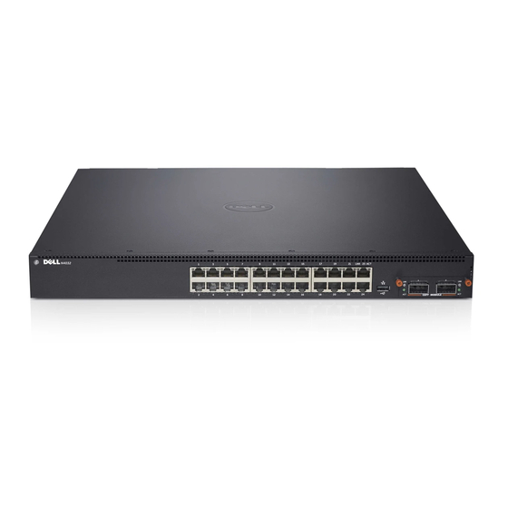
• Dell Networking N2000 Series Switch Hardware • Dell Networking N3000 Series Switch Hardware • Dell Networking N4000 Series Switch Hardware • Switch MAC Addresses Dell Networking N2000 Series Switch Hardware This section contains information about device characteristics and modular hardware configurations for the N2000 series switches. - Page 92 Figure 3-1. N2048 Switch with 48 10/100/1000BASE-T Ports (Front Panel) USB Port Console Port 48 10/100/1000BASE-T Ports SFP+ Ports In addition to the switch ports, the front panel of each model in the N2000 series includes the following ports: • Console port •...
- Page 93 SFP+ ports support Dell-qualified transceivers. The default behavior is to log a message and generate an SNMP trap on insertion or removal of an optic that is not qualified by Dell. The message and trap can be suppressed by using the service unsupported-transceiver command.
- Page 94 The Type-A, female USB port supports a USB 2.0-compliant flash memory drive. The Dell Networking switch can read or write to a flash drive with a single partition formatted as FAT-32. You can use a USB flash drive to copy switch configuration files and images between the USB flash drive and the switch.
-
Page 95: N2000 Series Back Panel
Port and System LEDs The front panel contains light emitting diodes (LEDs) that indicate the status of port links, power supplies, fans, stacking, and the overall system status. See "N2000 LED Definitions" on page 97 for more information. Stack Master LED and Stack Number Display When a switch within a stack is the master unit, the stack master LED, which is labeled M, is solid green. - Page 96 Power Supplies N2024 and N2048 N2024 and N2048 series switches have an internal 100-watt power supply. The additional redundant power supply (Dell Networking RPS720) provides 180 watts of power and gives full redundancy for the switch. N2024P and N2048P N2024P and N2048P switches have an internal 1000-watt power supply feeding up to 24 PoE devices at full PoE+ power (850W).
-
Page 97: N2000 Led Definitions
N2000 LED Definitions This section describes the LEDs on the front and back panels of the switch. Port LEDs Each port on an N2000 switch includes two LEDs. One LED is on the left side of the port, and the second LED is on the right side of the port. This section describes the LEDs on the switch ports. - Page 98 Table 3-16 shows the 100/1000/10000Base-T port LED definitions. Table 3-1. 100/1000/10000Base-T Port Definitions Color Definition Link/SPD LED Off There is no link. Solid yellow The port is operating at 10/100 Mbps. Solid green The port is operating at 1000 Mbps. Activity LED There is no current transmit/receive activity.
- Page 99 Table 3-3. Console Port LED Definitions Color Definition Link/SPD LED Off There is no link. Solid green A link is present. System LEDs The system LEDs, located on the back panel, provide information about the power supplies, thermal conditions, and diagnostics. Table 3-21 shows the System LED definitions for the N2000 series switches.
-
Page 100: Power Consumption For N2000 Series Poe Switches
Table 3-4. System LED Definitions (Continued) Color Definition Stack The switch is in stand-alone mode. master Solid green The switch is master for the stack. Temp Solid green The switch is operating below the threshold temperature. Solid red The switch temperature exceeds the threshold of 75°C. Stack No. - Page 101 Table 3-6. N2000 Series PoE Power Budget Limit One PSU Support Two PSUs Support Model System Power Max. PSU POE+ Power Max. PSUs POE+ Power Name Max. Dissipation Output Ability Turn-on Limitation Output Ability Turn-on Limitation N2024P 1000W Power budget is 2000W Power budget is 850W:...
-
Page 102: Dell Networking N3000 Series Switch Hardware
Dell Networking N3000 Series Switch Hardware This section contains information about device characteristics and modular hardware configurations for the N3000 series switches. N3000 Series Front Panel The N2000 series front panel includes the following features: • Switch Ports • Console Port •... - Page 103 Figure 3-9. N3048 with 48 10/100/1000BASE-T Ports (Front Panel) Combo 10/100/1000BASE-T Auto-sensing Full Duplex RJ-45 Ports Ports SFP+ Ports The additional ports are on the right side of the front panel, as shown in Figure 3-9 and Figure 3-10 on page 103. Figure 3-10.
- Page 104 SFP+ ports support Dell-qualified transceivers. The default behavior is to log a message and generate an SNMP trap on insertion or removal of an optic that is not qualified by Dell. The message and trap can be suppressed by using the service unsupported-transceiver command.
- Page 105 The Type-A, female USB port supports a USB 2.0-compliant flash memory drive. The Dell Networking switch can read or write to a flash drive with a single partition formatted as FAT-32. You can use a USB flash drive to copy switch configuration files and images between the USB flash drive and the switch.
-
Page 106: N3000 Series Back Panel
Port and System LEDs The front panel contains light emitting diodes (LEDs) that indicate the status of port links, power supplies, fans, stacking, and the overall system status. User’s For information about the status that the LEDs indicate, see the Configuration Guide. - Page 107 Figure 3-13. N3048 Mini-SAS Stacking Ports Close-up Mini-SAS stacking ports The term mini-SAS refers to the stacking port cable connections shown in Figure 3-13. See "Managing a Switch Stack" on page 171 for information on using the mini-SAS ports to connect switches. Expansion Slots for Plug-in Modules One expansion slot is located on the back of the N3000 models and can support the following modules:...
- Page 108 N3024P and N3048P Dell Networking N3024P and N3048P switches support one or two 1100-watt FRU power supplies. The N3024P switch is supplied with a single 715-watt power supply (the default configuration) and supports an additional 1100-watt supply. For the N3048P switch, a single 1100-watt power supply is supplied and another 1100 watt power supply can be added.
-
Page 109: Led Definitions
LED Definitions This section describes the LEDs on the front and back panels of the switch. Port LEDs Each port on an N3000 series switch includes two LEDs. One LED is on the left side of the port, and the second LED is on the right side of the port. This section describes the LEDs on the switch ports. - Page 110 Table 3-16 shows the 100/1000/10000Base-T port LED definitions. Table 3-7. 100/1000/10000Base-T Port Definitions Color Definition Link/SPD LED Off There is no link. Solid yellow The port is operating at 10/100 Mbps. Solid green The port is operating at 1000 Mbps. Activity LED There is no current transmit/receive activity.
- Page 111 Table 3-9. 10GBase-T Module LED Definitions Color Definition Link/SPD LED Off There is no link. Solid green The port is operating at 10 Gbps. Solid amber The port is operating at 100/1000 Mbps. Activity LED There is no current transmit/receive activity. Blinking green The port is actively transmitting/receiving.
- Page 112 Table 3-12. Console Port LED Definitions Color Definition Link/SPD LED Off There is no link. Solid green A link is present. System LEDs The system LEDs, located on the back panel, provide information about the power supplies, thermal conditions, and diagnostics. Table 3-21 shows the System LED definitions for the N3000 series switches.
-
Page 113: Power Consumption For N3000 Series Poe Switches
Power Consumption for N3000 Series PoE Switches Table 3-14 shows power consumption data for the PoE-enabled switches. Table 3-14. N3000 Series Power Consumption Model Input Power Supply Max Steady Max Steady Voltage Configuration Current Power (W) Consumption (A) N3024P 100V PSU1+PSU2 13.1 1310.0... - Page 114 Table 3-15. N3000 Series PoE Power Budget Limit One PSU Support Two PSUs Support Model System Power Max. PSU POE+ Power Max. PSUs POE+ Power Name Max. Dissipation Output Ability Turn-on Limitation Output Ability Turn-on Limitation N3024P 110W 715W Power budget is 715W Power budget is 550W:...
-
Page 115: Dell Networking N4000 Series Switch Hardware
6.1. This section contains information about device characteristics and modular hardware configurations for the N4000 series switches. Front Panel The N4000 series front panel includes the following features: • Switch ports • Module bay that supports the following modules: –... - Page 116 Figure 3-15. N4024 Front Panel 10GbE Copper Ports Module bay USB port Figure 3-16. N4024F Front Panel 10GbE Fiber Ports Module bay USB port N4032 and N4032F switches can be stacked with other N4000 switches using 10G or 40G SFP+ or QSFP modules in the module bay. The N4064 front panel provides 64 x 10GbE copper ports and two fixed QSFP ports, each supporting 4 x 10G or 1 x 40G connections.
- Page 117 Figure 3-17. N4064 Front Panel Module bay USB port Fixed QSFP 10GbE Copper Ports ports Figure 3-18. N4064F Front Panel Module bay USB port 10GbE Fiber Ports Fixed QSFP ports The N4064 and N4064F switches can be stacked with other N4000 switches using the 10G or 40G SFP+ or QSFP modules in the module bay or fixed QSFP ports.
- Page 118 If a no slot command is not issued prior to inserting a module, a message such as the following will appear: Card Mismatch: Unit:1 Slot:1 Inserted-Card: Dell 2 Port QSFP Expansion Card Config-Card: Dell 4 Port 10GBase-T Expansion Card The following sections provides details on each module.
-
Page 119: N4000 Back Panel
SFP+ and QSFP+ ports support Dell-qualified transceivers. The default behavior is to log a message and generate an SNMP trap on insertion or removal of an optic that is not qualified by Dell. This message and trap can be suppressed by using the service unsupported-transceiver command. - Page 120 • Ventilation System The following image show the back panel of the N4000 series switches. Figure 3-19. N4000 Series Back Panel RJ-45 serial console port AC power OOB Ethernet port Fans AC power Console Port The console port is for management through a serial interface. This port...
-
Page 121: Led Definitions
This section describes the LEDs on the front and back panels of the switch. Port LEDs Each port on a N4000 series switch includes two LEDs. One LED is on the left side of the port, and the second LED is on the right side of the port. This section describes the LEDs on the switch ports. - Page 122 Table 3-16 shows the 100/1000/10000Base-T port LED definitions. Table 3-16. 100/1000/10000Base-T Port Definitions Color Definition Link LED There is no link. Solid green The port is operating at 10 Gbps. Solid amber The port is operating at 100/1000 Mbps. Activity LED There is no current transmit/receive activity.
- Page 123 Table 3-19. QSFP Module LED Definitions Color Definition Link LED There is no link. Solid green The port is operating at 40 Gbps. Solid amber The port is operating at other speeds. Activity LED There is no current transmit/receive activity. Blinking green The port is actively transmitting/receiving.
- Page 124 Table 3-21 shows the System LED definitions for the N4000 series switches. Table 3-21. System LED Definitions—N4000 Series Switches Color Definition System Blinking blue The switch is booting Solid red A critical system error has occurred. Blinking red A noncritical system error occurred (fan or power supply failure).
-
Page 125: Switch Mac Addresses
Base + 3 Layer 3 Shown below are three commands that display the MAC addresses used by the switch: console#show system System Description: Dell Ethernet Switch System Up Time: 0 days, 00h:05m:11s System Contact: System Name: System Location: Burned In MAC Address: 001E.C9F0.004D System Object ID: 1.3.6.1.4.1.674.10895.3042... - Page 126 System 42.0 43.4 Main 04/06/2001 16:36:16 Secondary No Power 01/01/1970 00:00:00 USB Port Power Status: ---------------------- Device Not Present console#show ip interface out-of-band IP Address........10.27.21.29 Subnet Mask........255.255.252.0 Default Gateway........ 10.27.20.1 Configured IPv4 Protocol....... DHCP Burned In MAC Address......001E.C9F0.004E console#show ip interface vlan 1 Routing Interface Status.......
-
Page 127: Using Dell Openmanage Switch
About Dell OpenManage Switch Administrator Dell OpenManage Switch Administrator is a web-based tool to help you manage and monitor a Dell Networking N2000, N3000, and N4000 series switches. Table 4-1 lists the web browsers that are compatible with Dell OpenManage Switch Administrator. The browsers have been tested on a PC running the Microsoft Windows operating system. -
Page 128: Starting The Application
Starting the Application To access the Dell OpenManage Switch Administrator and log on to the switch: 1 Open a web browser. 2 Enter the IP address of the switch in the address bar and press <Enter>. For information about assigning an IP address to a switch, see "Setting the IP Address and Other Basic Network Information"... -
Page 129: Understanding The Interface
5 The Dell OpenManage Switch Administrator home page displays. The home page is the Device Information page, which contains a graphical representation of the front panel of the switch. For more information about the home page, see "Device Information" on page 249. - Page 130 Figure 4-2. Switch Administrator Components Save, Print, Refresh, Help Navigation Panel Page Tabs Links Configuration and Status Options Command Button Using Dell OpenManage Switch Administrator...
-
Page 131: Using The Switch Administrator Buttons And Links
Using the Switch Administrator Buttons and Links Table 4-2 describes the buttons and links available from the Dell OpenManage Switch Administrator interface. Table 4-2. Button and Link Descriptions Button or Link Description Support support.dell.com Opens the Dell Support page at... -
Page 132: Defining Fields
Defining Fields User-defined fields can contain 1 159 characters, unless otherwise noted on – the Dell OpenManage Switch Administrator web page. All characters may be used except for the following: • • • • • • < • > •... -
Page 133: Using The Device View Switch Locator Feature
After you click the Locate button it turns green and remains green while the LED is blinking. NOTE: locate You can also issue the command from the CLI to enable the locator LED. Using Dell OpenManage Switch Administrator... - Page 134 Using Dell OpenManage Switch Administrator...
-
Page 135: Using The Command-Line Interface
On N2000 and N3000 series switches, the console port is located on the right side of the front panel and is labeled with the |O|O| symbol. On the N4000 series switches, it is located on the back panel above the OOB Ethernet port. -
Page 136: Telnet Connection
NOTE: For a stack of switches, be sure to connect to the console port on the Master switch. The Master LED (M) is illuminated on the stack Master. 2 Start the terminal emulator, such as Microsoft HyperTerminal, and select the appropriate serial port (for example, COM 1) to connect to the console. -
Page 137: Understanding Command Modes
You can also initiate a Telnet session from the OpenManage Switch Administrator. For more information, see "Initiating a Telnet Session from the Web Interface" on page 288. Understanding Command Modes The CLI groups commands into modes according to the command function. Each of the command modes supports specific software commands. - Page 138 Table 5-1. Command Mode Overview Command Mode Access Method Command Prompt Exit or Access Previous Mode User EXEC The user is logout console> automatically in User EXEC mode unless the user is defined as a privileged user. Privileged EXEC From User Use the exit console# EXEC mode,...
-
Page 139: Entering Cli Commands
Entering CLI Commands The switch CLI uses several techniques to help you enter commands. Using the Question Mark to Get Help Enter a question mark (?) at the command prompt to display the commands available in the current mode. console(config-vlan)#? exit To exit from the mode. -
Page 140: Using Command Completion
If there are no additional command keywords or parameters, or if additional parameters are optional, the following message appears in the output: <cr> Press enter to execute the command. You can also enter a question mark (?) after typing one or more characters of a word to list the available command or parameters that begin with the letters, as shown in the following example: console#show po? -
Page 141: Command Output Paging
Command Output Paging Lines are printed on the screen up to the configured terminal length limit (default 24). Use the space bar to show the next page of output or the carriage return to show the next line of output. Setting the terminal length to zero disables paging. - Page 142 Table 5-3. History Buffer Navigation Keyword Source or Destination Up-arrow key Recalls commands in the history buffer, beginning with the most recent command. Repeats the key sequence to recall successively <Ctrl>+<P> older commands. Down-arrow key Returns to more recent commands in the history buffer after recalling commands with the up-arrow key.
-
Page 143: Default Settings
Default Settings This section describes the default settings for many of the software features on the Dell Networking series switches. Table 6-1. Default Settings Feature Default IP address None Subnet mask None Default gateway None DHCP client Enabled on out-of-band (OOB) interface. - Page 144 Table 6-1. Default Settings (Continued) Feature Default SNMP Traps Enabled Auto Configuration Enabled Auto Save Disabled Stacking Enabled Nonstop Forwarding on the Stack Enabled sFlow Enabled ISDP Enabled (Versions 1 and 2) RMON Enabled TACACS+ Not configured RADIUS Not configured SSH/SSL Disabled Telnet...
- Page 145 Table 6-1. Default Settings (Continued) Feature Default Auto-MDI/MDIX Support Enabled Auto Negotiation Enabled Advertised Port Speed Maximum Capacity Broadcast Storm Control Disabled Port Mirroring Disabled LLDP Enabled LLDP-MED Disabled MAC Table Address Aging 300 seconds (Dynamic Addresses) Cisco Protocol Filtering (LLPF) No protocols are blocked DHCP Layer 2 Relay Disabled...
- Page 146 Table 6-1. Default Settings (Continued) Feature Default Routing Mode Disabled OSPF Admin Mode Enabled OSPF Router ID 0.0.0.0 IP Helper and UDP Relay Enabled Enabled VRRP Disabled Tunnel and Loopback Interfaces None IPv6 Routing Disabled DHCPv6 Disabled OSPFv3 Enabled DiffServ Enabled Auto VoIP Disabled...
-
Page 147: Setting The Ip Address And Other
What Is the Basic Network Information? The basic network information includes settings that define the Dell Networking N2000, N3000, and N4000 series switches in relation to the network. Table 7-1 provides an overview of the settings this chapter describes. Table 7-1. Basic Network Information... -
Page 148: Why Is Basic Network Information Needed
Why Is Basic Network Information Needed? Dell Networking series switches are layer 2/3 managed switches. To manage the switch remotely by using a web browser or Telnet client, the switch must have an IP address, subnet mask, and default gateway. -
Page 149: How Is Basic Network Information Configured
You must use a console-port connection to perform the initial switch configuration. When you boot the switch for the first time and the configuration file is empty, the Dell Easy Setup Wizard starts. The Dell Easy Setup Wizard is a CLI-based tool to help you perform the initial switch configuration. - Page 150 This is required to manage the N2000 switches over an Ethernet port. Dell recommends that you use the OOB port for remote management. The following list highlights some advantages of using OOB management instead of in-band management: •...
-
Page 151: Default Network Information
transmitted from the switch with the DF (Don't Fragment) bit set in order to receive notification of fragmentation from any transit routers. Upon receiving Destination Unreachable, Fragmentation needed but DF set an ICMP notification, the switch will reduce the MSS. However, many firewalls block ICMP Destination Unreachable messages, which causes the destination to request the packet again until the connection times out. -
Page 152: Configuring Basic Network Information (Web)
This section provides information about the OpenManage Switch Administrator pages for configuring and monitoring basic network information on the Dell Networking N2000, N3000, and N4000 series switches. For details about the fields on a page, click at the top of the page. -
Page 153: Ip Interface Configuration (Default Vlan Ip Address)
Figure 7-1. Out of Band Interface To enable the DHCP client and allow a DHCP server on your network to automatically assign the network information to the OOB interface, select DHCP from the Protocol menu. If you statically assign the network information, make sure the Protocol menu is set to None. - Page 154 Figure 7-2. IP Interface Configuration (Default VLAN) Assigning Network Information to the Default VLAN To assign an IP Address and subnet mask to the default VLAN: 1 From the Interface menu, select VLAN 1. 2 From the Routing Mode field, select Enable. 3 From the IP Address Configuration Method field specify whether to assign a static IP address (Manual) or use DHCP for automatic address assignment.
-
Page 155: Route Entry Configuration (Switch Default Gateway)
NOTE: You do not need to configure any additional fields on the page. For information about VLAN routing interfaces, see "Configuring Routing Interfaces" on page 1021. Route Entry Configuration (Switch Default Gateway) Use the Route Entry Configuration page to configure the default gateway for the switch. - Page 156 Configuring a Default Gateway for the Switch: To configure the switch default gateway: 1 Open the Route Entry Configuration page. 2 From the Route Type field, select Default. Figure 7-4. Default Route Configuration (Default VLAN) 3 In the Next Hop IP Address field, enter the IP address of the default gateway.
-
Page 157: Domain Name Server
Domain Name Server Use the Domain Name Server page to configure the IP address of the DNS server. The switch uses the DNS server to translate hostnames into IP addresses. To display the Domain Name Server page, click System → IP Addressing → Domain Name Server in the navigation panel. -
Page 158: Default Domain Name
Default Domain Name Use the Default Domain Name page to configure the domain name the switch adds to a local (unqualified) hostname. To display the Default Domain Name page, click System → IP Addressing → Default Domain Name in the navigation panel. Figure 7-7. -
Page 159: Host Name Mapping
Host Name Mapping Use the Host Name Mapping page to assign an IP address to a static host name. The Host Name Mapping page provides one IP address per host. To display the Host Name Mapping page, click System → IP Addressing → Host Name Mapping. -
Page 160: Dynamic Host Name Mapping
The switch learns hosts dynamically by using the configured DNS server to resolve a hostname. For example, if you ping www.dell.com from the CLI, the switch uses the DNS server to lookup the IP address of dell.com and adds the entry to the Dynamic Host Name Mapping table. -
Page 161: Configuring Basic Network Information (Cli)
Configuring Basic Network Information (CLI) This section provides information about the commands you use to configure basic network information on the Dell Networking N2000, N3000, and N4000 Dell series switches. For more information about these commands, see the Networking N2000, N3000, and N4000 Series Switches CLI Reference Guide at support.dell.com/manuals. -
Page 162: Managing Dhcp Leases
Command Purpose CTRL + Z Exit to Privileged EXEC mode. show ip interface vlan 1 Display network information for VLAN 1. Managing DHCP Leases Beginning in Privileged EXEC mode, use the following commands to manage and troubleshoot DHCP leases on the switch. Command Purpose show dhcp lease... -
Page 163: Configuring Static Network Information On The Oob Port
Configuring Static Network Information on the OOB Port NOTE: N2000 switches do not have an out-of-band interface. Beginning in Privileged EXEC mode, use the following commands to configure a static IP address, subnet mask, and default gateway on the OOB port. -
Page 164: Configuring And Viewing Additional Network Information
Static IP subnets on inband ports (configured on switch VLANs) may not overlap with the OOB port subnet. If configuring management access on the front-panel ports, it is recomended that: • A VLAN other than the default VLAN be used to avoid attack vectors enabled by incorrect cabling. - Page 165 Command Purpose configure Enter Global Configuration mode. ip domain-lookup Enable IP DNS-based host name-to-address translation. ip name-server Enter the IP address of an available name server to use to ip_address resolve host names and IP addresses. You can specify up to six DNS servers. The first server you configure is the primary DNS server.
-
Page 166: Basic Network Information Configuration Example
Basic Network Information Configuration Example In this example, an administrator at a Dell office in California decides not to use the Dell Easy Setup Wizard to perform the initial switch configuration. The administrator configures a Dell Networking N2000, N3000, and N4000... - Page 167 Default Gateway....10.27.22.1 Protocol Current....DHCP Burned In MAC Address.... 001E.C9AA.AA08 5 View additional network information. console#show hosts Host name: Default domain: sunny.dell.com dell.com Name/address lookup is enabled Name servers (Preference order): 10.27.138.20, 10.27.138.21 Configured host name-to-address mapping: Host Addresses...
- Page 168 Setting Basic Network Information...
-
Page 169: Managing Qsfp Ports
Managing QSFP Ports QSFP ports available on N4000 series switches can operate in 1 x 40G mode or in 4 x 10G mode. Appropriate cables must be used that match the selected mode. When changing from one mode to another, a switch reboot is required. - Page 170 To change a 4 x 10G port to 1 x 40G mode, enter the following commands on the 40-gigabit interface: console(config)#interface Fo2/1/1 console(config-if-Fo2/1/1)#hardware profile portmode 1x40g This command will not take effect until the switch is rebooted. console(config-if-Fo1/1/2)#do reload Are you sure you want to reload the stack? (y/n) Attempting to change the port mode on the tengigabit interface will give the error “An invalid interface has been used for this function.”...
-
Page 171: Managing A Switch Stack
Stacking and NSF Usage Scenarios Stacking Overview The Dell Networking N2000, N3000, and N4000 and series switches include a stacking feature that allows up to 12 switches to operate as a single unit. The N2000 and N3000 series switches have two fixed mini-SAS stacking connectors at the rear. - Page 172 In other words, all the port types on the N4000 series switches can be used for stacking. Additional stacking connections can be made between adjacent switch units to increase the stacking bandwidth provided that all redundant stacking links have the same port speed.
- Page 173 Dell strongly recommends connecting the stack in a ring topology so that each switch is connected to two other switches. Connecting switches in a ring topology allows the stack to utilize the redundant communication path to each switch.
-
Page 174: Dell Networking N2000, N3000, And N4000 Stacking Compatibility
Unit 1. Dell Networking N2000, N3000, and N4000 Stacking Compatibility Dell Networking N2000, N3000, and N4000 series switches do not stack with different Dell Networking series switches or Dell PowerConnect series switches. Dell Networking N2000 series switches only stack with other N2000... -
Page 175: How Is The Stack Master Selected
Likewise, Dell Networking N3000 series switches only stack with other Dell N3000 series switches. Dell Networking N4000 series switches stack with other Dell Networking N4000 series switches. How is the Stack Master Selected? A stack master is elected or re-elected based on the following considerations, in order: 1 The switch is currently the stack master. -
Page 176: Adding A Switch To The Stack
• If the switch you add does not have an assigned unit number, then the switch sets its configured unit number to the lowest unassigned unit number. • If the unit number is configured and there are no other devices using the unit number, then the switch starts using the configured unit number. -
Page 177: Removing A Switch From The Stack
You can preconfigure information about a stack member and its ports before you add it to the stack. The preconfiguration takes place on the stack master. If there is saved configuration information on the stack master for the newly added unit, the stack master applies the configuration to the new unit; otherwise, the stack master applies the default configuration to the new unit. -
Page 178: What Is Stacking Standby
What is Nonstop Forwarding? Networking devices, such as the Dell Networking series switches, are often described in terms of three semi-independent functions called the forwarding plane, the control plane, and the management plane. The forwarding plane forwards data packets and is implemented in hardware. - Page 179 on the stack master. This type of operation is called nonstop forwarding. When the stack master fails, only the switch ASICs on the stack master need to be restarted. To prevent adjacent networking devices from rerouting traffic around the restarting device, the NSF feature uses the following three techniques: 1 A protocol can distribute a part of its control plane to stack units so that the protocol can give the appearance that it is still functional during the restart.
- Page 180 storage allows an application on a standalone unit to retain its data across a restart, but since the amount of storage is limited, persistent storage is not always practical. The NSF checkpoint service allows the stack master to communicate certain data to the backup unit in the stack.
-
Page 181: Switch Stack Mac Addressing And Stack Design Considerations
Table 9-1. Applications that Checkpoint Data Application Checkpointed Data OSPFv2 Neighbors and designated routers OSPFv3 Neighbors and designated routers Route Table Manager IPv4 and IPv6 dynamic routes The system's MAC addresses. System up time. IP address, network mask, default gateway on each management interface, DHCPv6 acquired IPv6 address. -
Page 182: Why Is Stacking Needed
Why is Stacking Needed? Stacking increases port count without requiring additional configuration. If you have multiple Dell Networking switches, stacking them helps make management of the switches easier because you configure the stack as a single unit and do not need to configure individual switches. - Page 183 two fixed stacking ports in the rear of the switch. Stacking on Ethernet ports is not supported. The fixed stacking ports show as TwentygigabitStacking and are abbreviated Tw. NSF is enabled by default. You can disable NSF to redirect the CPU resources consumed by data checkpointing.
-
Page 184: Managing And Monitoring The Stack (Web)
This section provides information about the OpenManage Switch Administrator pages for configuring and monitoring stacking on a Dell Networking N2000, N3000, and N4000 series switches. For details about the fields on a page, click at the top of the page. -
Page 185: Stack Summary
Changing the ID or Switch Type for a Stack Member To change the switch ID or type: 1 Open the Unit Configuration page. 2 Click Add to display the Add Unit page. Figure 9-3. Add Remote Log Server Settings 3 Specify the switch ID, and select the model number of the switch. 4 Click Apply. -
Page 186: Stack Firmware Synchronization
Stack Firmware Synchronization Use the Stack Firmware Synchronization page to control whether the firmware image on a new stack member can be automatically upgraded or downgraded to match the firmware image of the stack master. To display the Stack Firmware Synchronization page, click System → Stack Management →... -
Page 187: Supported Switches
Supported Switches Use the Supported Switches page to view information regarding each type of supported switch for stacking, and information regarding the supported switches. To display the Supported Switches page, click System → Stack Management → Supported Switches in the navigation panel. Figure 9-6. -
Page 188: Stack Port Summary
Stack Port Summary Use the Stack Port Summary page to configure the stack-port mode and to view information about the stackable ports. This screen displays the unit, the stackable interface, the configured mode of the interface, the running mode as well as the link status and link speed of the stackable port. NOTE: By default the ports are configured to operate as Ethernet ports. -
Page 189: Stack Port Counters
Stack Port Counters Use the Stack Port Counters page to view the transmitted and received statistics, including data rate and error rate. To display the Stack Port Counters page, click System → Stack Management → Stack Point Counters in the navigation panel. Figure 9-8. -
Page 190: Nsf Summary
NSF Summary Use the NSF Summary page to change the administrative status of the NSF feature and to view NSF information. NOTE: The OSPF feature uses NSF to enable the hardware to continue forwarding IPv4 packets using OSPF routes while a backup unit takes over stack master responsibility. -
Page 191: Checkpoint Statistics
Checkpoint Statistics Use the Checkpoint Statistics page to view information about checkpoint messages generated by the stack master. To display the Checkpoint Statistics page, click System → Stack Management → Checkpoint Statistics in the navigation panel. Figure 9-10. Checkpoint Statistics Managing a Switch Stack... -
Page 192: Managing The Stack (Cli)
For more information Dell Networking N2000, N3000, and N4000 about these commands, see the Series Switches CLI Reference Guide at support.dell.com/manuals. Configuring Stack Member, Stack Port, and NSF Settings Beginning in Privileged EXEC mode, use the following commands to configure stacking and NSF settings. - Page 193 Command Purpose unit SID member Add a switch to the stack and specify the model of the new stack member. unit • - The switch unit ID • - The index into the database of the supported switch types, indicating the type of the switch being preconfigured.
-
Page 194: Viewing And Clearing Stacking And Nsf Information
View the path that packets take from one stack member to stack-path another. show supported View the Dell Networking models that are supported in switchtype the stack and the switch index (SID) associated with each model. show nsf View summary information about the NSF feature. -
Page 195: Stacking And Nsf Usage Scenarios
Stacking and NSF Usage Scenarios Only a few settings are available to control the stacking configuration, such as the designation of the standby unit or enabling/disabling NSF. The examples in this section describe how the stacking and NSF feature act in various environments. - Page 196 When all four units are up and running, the show switch CLI command gives the following output: console#show switch Management Standby Preconfig Plugged- Switch Code Status Status Model ID in Model Status Version --------- ------- -------- --------- ------- -------- Stack Member N3048 N3048 6.0.0.0...
-
Page 197: Preconfiguring A Stack Member
To preconfigure a stack member before connecting the physical unit to the stack, use the show support switchtype command to obtain the SID of the unit to be added. The example in this section demonstrates pre-configuring a Dell Networking switch on a stand-alone Dell Networking switch. To configure the switch: 1 View the list of SIDs to determine which SID identifies the switch to preconfigure. - Page 198 2 Preconfigure the switch (SID = 2) as member number 2 in the stack. console#configure console(config)#stack console(config-stack)#member 2 2 console(config-stack)#exit console(config)#exit 3 Confirm the stack configuration. Some of the fields have been omitted from the following output due to space limitations. console#show switch Management Standby Preconfig...
-
Page 199: Nsf In The Data Center
NSF in the Data Center Figure 9-12 illustrates a data center scenario, where the stack of two Dell Networking switches acts as an access switch. The access switch is connected to two aggregation switches, AS1 and AS2. The stack has a link from two different units to each aggregation switch, with each pair of links grouped together in a LAG. -
Page 200: Nsf And Voip
NSF and VoIP Figure 9-13 shows how NSF maintains existing voice calls during a stack master failure. Assume the top unit is the stack master. When the stack master fails, the call from phone A is immediately disconnected. The call from phone B continues. -
Page 201: Nsf And Dhcp Snooping
NSF and DHCP Snooping Figure 9-14 illustrates an L2 access switch running DHCP snooping. DHCP trusted snooping only accepts DHCP server messages on ports configured as ports. DHCP snooping listens to DHCP messages to build a bindings database that lists the IP address the DHCP server has assigned to each host. IP Source Guard (IPSG) uses the bindings database to filter data traffic in hardware based on source IP address and source MAC address. -
Page 202: Nsf And The Storage Access Network
IP address lease with the DHCP server. NSF and the Storage Access Network Figure 9-15 illustrates a stack of three Dell Networking switches connecting two servers (iSCSI initiators) to a disk array (iSCSI targets). There are two iSCSI connections as follows: Session A: 10.1.1.10 to 10.1.1.3... - Page 203 Figure 9-15. NSF and a Storage Area Network When the stack master fails, session A drops. The initiator at 10.1.1.10 detects a link down on its primary NIC and attempts to reestablish the session on its backup NIC to a different IP address on the disk array. The hardware forwards the packets to establish this new session, but assuming the session is established before the control plane is restarted on the backup unit, the new session receives no priority treatment in the hardware.
-
Page 204: Nsf And Routed Access
NSF and Routed Access Figure 9-16 shows a stack of three units serving as an access router for a set of hosts. Two LAGs connect the stack to two aggregation routers. Each LAG is a member of a VLAN routing interface. The stack has OSPF and PIM adjacencies with each of the aggregation routers. - Page 205 JOIN messages upstream. The control plane updates the driver with checkpointed unicast routes. The forwarding plane reconciles L3 hardware tables. The OSPF graceful restart finishes, and the control plane deletes any stale unicast routes not relearned at this point. The forwarding plane reconciles L3 multicast hardware tables.
- Page 206 Managing a Switch Stack...
-
Page 207: Configuring Authentication
Configuring Authentication, Authorization, and Accounting This chapter describes how to control access to the switch management interface using authentication and authorization. It also describes how to record this access using accounting. Together the three services are referred to by the acronym AAA. The topics covered in this chapter include: •... -
Page 208: Methods
Each service is configured using method lists. The method lists define how each service is to be performed by specifying the methods available to perform a service. The first method in a list is tried first. If the first method returns an error, the next method in the list is tried. -
Page 209: Access Lines
Methods that never return an error cannot be followed by any other methods in a method list. • The enable method uses the enable password. If there is no enable password defined, then the enable method will return an error. The ias method is a special method that is only used for 802.1X. - Page 210 The methods available for authentication are: host-based authentication, public key authentication, challenge-response authentication, and password authentication. Authentication methods are tried in the order specified above, although SSH-2 has a configuration option to change the default order. Host-based authentication operates as follows: If the host from which the user logs in is listed in a specific file (/etc/hosts.equiv or /etc/ssh/shosts.equiv) on the remote host, and the user names are the same on both hosts, or if the files ~/.rhosts or ~/.shosts exist in...
-
Page 211: Authentication
Authentication Authentication is the process of validating a user's identity. During the authentication process, only identity validation is done. There is no determination made of which switch services the user is allowed to access. This is true even when RADIUS is used for authentication; RADIUS cannot perform separate transactions for authentication and authorization. -
Page 212: Authorization
Exec Authorization Capabilities Dell Networking switches support two types of service configuration with exec authorization: privilege level and administrative profiles. Privilege Level By setting the privilege level during exec authorization, a user can be placed directly into Privileged EXEC mode when they log into the command line interface. - Page 213 Administrative Profiles The Administrative Profiles feature allows the network administrator to define a list of rules that control the CLI commands available to a user. These rules are collected in a “profile.” The rules in a profile can define the set of commands, or a command mode, to which a user is permitted or denied access.
-
Page 214: Accounting
Accounting Accounting is used to record security events, such as a user logging in or executing a command. Accounting records may be sent upon completion of an event (stop-only) or at both the beginning and end of an event (start- stop). -
Page 215: Authentication Examples
Authentication Examples It is important to understand that during authentication, all that happens is that the user is validated. If any attributes are returned from the server, they are not processed during authentication. In the examples below, it is assumed that the default configuration of authorization—that is, no authorization—is used. - Page 216 The passwords strength minimum numeric-characters 2 command sets • the minimum number of numeric characters required when password strength checking is enabled. This parameter is enabled only if the passwords strength minimum character-classes parameter is set to something greater than its default value of 0. •...
-
Page 217: Tacacs+ Authentication Example
TACACS+ Authentication Example Use the following configuration to require TACACS+ authentication when logging in over a Telnet connection: aaa authentication login “tacplus” tacacs aaa authentication enable “tacp” tacacs tacacs-server host 1.2.3.4 key “secret” exit line telnet login authentication tacplus enable authentication tacp exit The following describes each line in the above configuration: •... -
Page 218: Public Key Ssh Authentication Example
The following is an example of a public key configuration for SSH login. Using a tool such as putty and a private/public key infrastructure, one can enable secure login to the Dell Networking switch without a password. Instead, a public key is used with a private key kept locally on the administrator's computer. - Page 219 The crypto key pubkey-chain ssh command sets SSH to use a public key for the specified administrator login. The user login is specified by the username command, not the ias-user command. The key-string command enters the public key obtained from a key authority or from a tool such as PuTTyGen.
- Page 220 PUTTY Configuration Main Screen On the following screen, the IP address of the switch is configured and SSH is selected as the secure login protocol. Configuring Authentication, Authorization, and Accounting...
- Page 221 On the next screen, PUTTY is configured to use SSH-2 only. This is an optional step that accelerates the login process. Configuring Authentication, Authorization, and Accounting...
- Page 222 The following screen is the key to the configuration. It is set to display the authentication banner, disable authentication with Pageant, disable keyboard- interactive authentication (unless desired), disable attempted changes of user name, and select the private key file used to authenticate with the switch. Configuring Authentication, Authorization, and Accounting...
- Page 223 The following screen configures the user name to be sent to the switch. A user name is always required. Alternatively, leave Auto-login name blank and the system will prompt for a user name. Configuring Authentication, Authorization, and Accounting...
- Page 224 After configuring Putty, be sure to save the configuration. The following screen shows the result of the login process. The user name is entered automatically and the switch confirms that public key authentication occurs. Configuring Authentication, Authorization, and Accounting...
-
Page 225: Radius Authentication Example
Authenticating Without a Public Key When authenticating without the public key, the switch prompts for the user name and password. This is a SSH function, not a switch function. If the user knows the administrator login and password, then they are able to authenticate in this manner. - Page 226 The aaa authentication login “rad” radius command creates a login • authentication list called “rad” that contains the method radius. If this method returns an error, the user will fail to login. The aaa authentication enable “raden” radius command creates an •...
-
Page 227: Authorization Examples
Authorization Examples Authorization allows the administrator to control which services a user is allowed to access. Some of the things that can be controlled with authorization include the user's initial privilege level and which commands the user is allowed to execute. When authorization fails, the user is denied access to the switch, even though the user has passed authentication. -
Page 228: Tacacs+ Authorization Example-Administrative Profiles
The aaa authorization exec “tacex” tacacs command creates an exec • authorization method list called tacex which contains the method tacacs. • The authorization exec tacex command assigns the tacex exec authorization method list to be used for users accessing the switch via Telnet. -
Page 229: Tacacs+ Authorization Example-Custom Administrative Profile
TACACS+ Authorization Example—Custom Administrative Profile This example creates a custom profile that allows the user to control user access to the switch by configuring a administrative profile that only allows access to AAA related commands. Use the following commands to create the administrative profile: admin-profile aaa rule 99 permit command “^show aaa .*”... -
Page 230: Tacacs+ Authorization Example-Per-Command Authorization
string at the beginning of a line, the period (.) matches any single character, and the asterisk (*) repeats the previous match zero or more times. • To assign this profile to a user, configure the TACACS+ server so that it sends the following “roles”... -
Page 231: Radius Authorization Example-Direct Login To Privileged Exec Mode
profiles and per-command authorization are configured for a user, any command must be permitted by both the administrative profiles and by per- command authorization. RADIUS Authorization Example—Direct Login to Privileged EXEC Mode Apply the following configuration to use RADIUS for authorization, such that a user can enter privileged exec mode directly: aaa authorization exec “rad”... -
Page 232: Radius Authorization Example-Administrative Profiles
RADIUS Authorization Example—Administrative Profiles The switch should use the same configuration as in the previous authorization example. The RADIUS server should be configured such that it will send the Cisco AV Pair attribute with the “roles” value. For example: shell:roles=router-admin The above example attribute gives the user access to the commands permitted by the router-admin profile. - Page 233 The switch encrypts the supplied information, and a RADIUS client transports the request to a pre-configured RADIUS server. Figure 10-1. RADIUS Topology Backup RADIUS Server Dell Networking Switch Primary RADIUS Server Management Network Management Host The server can authenticate the user itself or make use of a back-end device to ascertain authenticity.
-
Page 234: Which Radius Attributes Does The Switch Support
rejects the user, it returns a negative result. If the server rejects the client or secrets the shared differ, the server returns no result. If the server requires additional verification from the user, it returns a challenge, and the request process begins again. - Page 235 Table 10-5. Supported RADIUS Attributes (Continued) Type RADIUS Attribute Name 802.1X User Manager Captive Portal IDLE-TIMEOUT TERMINATION-ACTION CALLED-STATION-ID CALLING-STATION-ID NAS-IDENTIFIER ACCT-STATUS-TYPE Set by RADIUS client for Accounting ACCT-INPUT-OCTETS ACCT-OUTPUT-OCTETS ACCT-SESSION-ID Set by RADIUS client for Accounting ACCT-SESSION-TIME ACCT-TERMINATECAUSE Yes ACCT- INPUTGIGAWORDS ACCT- OUTPUTGIGAWORDS...
-
Page 236: How Are Radius Attributes Processed On The Switch
How Are RADIUS Attributes Processed on the Switch? The following attributes are processed in the RADIUS Access-Accept message received from a RADIUS server: • NAS-PORT—ifIndex of the port to be authenticated. • REPLY-MESSAGE—Trigger to respond to the Access-Accept message with an EAP notification. •... -
Page 237: Using Tacacs+ Servers To Control Management Access
The client then uses the configured list of servers for authentication, and provides results back to the switch. Figure 10-2 shows an example of access management using TACACS+. Figure 10-2. Basic TACACS+ Topology Backup TACACS+ Server Dell Networking Switch Primary TACACS+ Server Management Network Management Host You can configure the TACACS+ server list with one or more hosts defined via their network IP address. -
Page 238: Which Tacacs+ Attributes Does The Switch Support
You can configure each server host with a specific connection type, port, timeout, and shared key, or you can use global configuration for the key and timeout. The TACACS+ server can do the authentication itself, or redirect the request to another back-end device. All sensitive information is encrypted and the shared secret is never passed over the network;... -
Page 239: Default Configurations
Default Configurations Method Lists The method lists shown in Table 10-7 are defined by default. They cannot be deleted, but they can be modified. Using the “no” command on these lists will return them to their default configuration. Table 10-7. Default Method Lists AAA Service (type) List Name List Methods... -
Page 240: Access Lines (Non-Aaa)
Table 10-8. Default AAA Methods (Continued) AAA Service (type) Console Telnet Accounting (exec) none none none Accounting none none none (commands) Access Lines (Non-AAA) Table 10-9 shows the default configuration of the access lines that do not use method lists. Table 10-9. - Page 241 Table 10-10. Default Administrative Profiles (Continued) Name Description CP-admin Allows access to the Captive Portal feature. network-operator Allows access to all User EXEC mode commands and show commands. Configuring Authentication, Authorization, and Accounting...
- Page 242 Configuring Authentication, Authorization, and Accounting...
-
Page 243: Monitoring And Logging System
Monitoring and Logging System Information This chapter provides information about the features you use to monitor the switch, including logging, cable tests, and email alerting. The topics covered in this chapter include: • System Monitoring Overview • Default Log Settings •... -
Page 244: Why Is System Information Needed
Why Is System Information Needed? The information the switch provides can help you troubleshoot issues that might be affecting system performance. The cable diagnostics test help you troubleshoot problems with the physical connections to the switch. Auditing access to the switch and the activities an administrator performed while managing the switch can help provide security and accountability. -
Page 245: What Are The Severity Levels
What Are the Severity Levels? For each local or remote log file, you can specify the severity of the messages to log. Each severity level is identified by a name and a number. Table 11-1 provides information about the severity levels. Table 11-1. -
Page 246: What Is The Log Message Format
The first part of the log message up to the first left bracket is fixed by the Syslog standard (RFC 3164). The second part up to the two percent signs is standardized for all Dell Networking logs. The variable text of the log message follows. The log message is limited to 96 bytes. -
Page 247: What Factors Should Be Considered When Configuring Logging
Stack ID —This is the assigned stack ID. For the Dell Networking N2000, N3000, and N4000 series switches, the stack ID number is always 1. The number 1 is used for systems without stacking ability. The top of stack is used to collect messages for the entire stack. -
Page 248: Default Log Settings
Default Log Settings System logging is enabled, and messages are sent to the console (severity level: warning and above), and RAM log (severity level: informational and above). Switch auditing, CLI command logging, Web logging, and SNMP logging are disabled. By default, no messages are sent to the log file that is stored in flash, and no remote log servers are defined. -
Page 249: Monitoring System Information And Configuring Logging (Web)
This section provides information about the OpenManage Switch Administrator pages to use to monitor system information and configure logging on the Dell Networking N2000, N3000, and N4000 series switches. For details about the fields on a page, click at the top of the page. - Page 250 Figure 11-2. Stack View For more information about the device view features, see "Understanding the Device View" on page 132. Monitoring and Logging System Information...
-
Page 251: System Health
System Health Use the Health page to view status information about the switch power and ventilation sources. To display the Health page, click System → General → Health in the navigation panel. Figure 11-3. Health Monitoring and Logging System Information... -
Page 252: System Resources
System Resources Use the System Resources page to view information about memory usage and task utilization. To display the System Resources page, click System → General → System Resources in the navigation panel. Figure 11-4. System Resources Monitoring and Logging System Information... -
Page 253: Unit Power Usage History
Unit Power Usage History Use the Unit Power Usage History page to view information about switch power consumption. To display the Unit Power Usage History page, click System → General → Unit Power Usage History in the navigation panel. Figure 11-5. Unit Power Usage History Monitoring and Logging System Information... -
Page 254: Integrated Cable Test For Copper Cables
Integrated Cable Test for Copper Cables Use the Integrated Cable Test for Copper Cables page to perform tests on copper cables. Cable testing provides information about where errors occurred in the cable, the last time a cable test was performed, and the type of cable error which occurred. -
Page 255: Optical Transceiver Diagnostics
To view a summary of all integrated cable tests performed, click the Show All link. Figure 11-7. Integrated Cable Test Summary Optical Transceiver Diagnostics Use the Transceiver Diagnostics page to perform tests on Fiber Optic cables. To display the Transceiver Diagnostics page, click System → Diagnostics → Transceiver Diagnostics in the navigation panel. - Page 256 Figure 11-8. Transceiver Diagnostics To view a summary of all optical transceiver diagnostics tests performed, click the Show All link. Figure 11-9. Transceiver Diagnostics Summary Monitoring and Logging System Information...
-
Page 257: Log Global Settings
Log Global Settings Use the Global Settings page to enable logging globally, to enable other types of logging. You can also specify the severity of messages that are logged to the console, RAM log, and flash-based log file. The Severity table lists log messages from the highest severity (Emergency) to the lowest (Debug). -
Page 258: Ram Log
RAM Log Use the RAM Log page to view information about specific RAM (cache) log entries, including the time the log was entered, the log severity, and a description of the log. To display the RAM Log, click System → Logs → RAM Log in the navigation panel. -
Page 259: Log File
Log File The Log File contains information about specific log entries, including the time the log was entered, the log severity, and a description of the log. To display the Log File, click System → Logs → Log File in the navigation panel. - Page 260 Figure 11-13. Remote Log Server Adding a New Remote Log Server To add a syslog server: 1 Open the Remote Log Server page. 2 Click Add to display the Add Remote Log Server page. 3 Specify the IP address or hostname of the remote server. 4 Define the UDP Port and Description fields.
- Page 261 Figure 11-14. Add Remote Log Server 5 Select the severity of the messages to send to the remote server. NOTE: When you select a severity level, all higher (numerically lower) severity levels are automatically selected. 6 Click Apply. Click the Show All link to view or remove remote log servers configured on the system.
-
Page 262: Email Alert Global Configuration
Email Alert Global Configuration Use the Email Alert Global Configuration page to enable the email alerting feature and configure global settings so that system log messages can be sent to from the switch to one or more email accounts. To display the Email Alert Global Configuration page, click System → Email Alerts →... - Page 263 Figure 11-17. Email Alert Mail Server Configuration Adding a Mail Server To add a mail server: 1 Open the Email Alert Mail Server Configuration page. 2 Click Add to display the Email Alert Mail Server Add page. 3 Specify the hostname of the mail server. Figure 11-18.
-
Page 264: Email Alert Subject Configuration
Figure 11-19. Show All Mali Servers Email Alert Subject Configuration Use the Email Alert Subject Configuration page to configure the subject line for email alerts that are sent by the switch. You can customize the subject for the message severity and entry status. To display the Email Alert Subject Configuration page, click System →... -
Page 265: Email Alert To Address Configuration
Figure 11-21. View Email Alert Subjects Email Alert To Address Configuration Use the Email Alert To Address Configuration page to specify where the email alerts are sent. You can configure multiple recipients and associate different message severity levels with different recipient addresses. To display the Email Alert To Address Configuration page, click System →... -
Page 266: Email Alert Statistics
Figure 11-23. View Email Alert To Address Configuration Email Alert Statistics Use the Email Alert Statistics page to view the number of emails that were successfully and unsuccessfully sent, and when emails were sent. To display the Email Alert Statistics page, click System → Email Alerts → Email Alert Statistics in the navigation panel. -
Page 267: Monitoring System Information And Configuring Logging (Cli)
This section provides information about the commands you use to configure information you use to monitor the Dell Networking N2000, N3000, and N4000 series switches. For more information about these commands, see the Dell Networking N2000, N3000, and N4000 Series Switches CLI Reference Guide at support.dell.com/manuals. -
Page 268: Running Cable Diagnostics
Command Purpose show process cpu Displays the CPU utilization for each process currently running on the switch. Running Cable Diagnostics Beginning in Privileged EXEC mode, use the following commands to run the cable diagnostic tests. NOTE: Cable diagnostics may give misleading results if green mode is enabled on the port. -
Page 269: Configuring Local Logging
Configuring Local Logging Beginning in Privileged EXEC mode, use the following commands to configure the type of messages that are logged and where the messages are logged locally. Command Purpose configure Enter Global Configuration mode. logging on Globally enables logging. logging audit Enable switch auditing. -
Page 270: Configuring Remote Logging
Command Purpose show logging Displays the state of logging and the syslog messages stored in the internal buffer. show logging file View information about the flash (persistent) log file. clear logging Use to clear messages from the logging buffer. Configuring Remote Logging Beginning in Privileged EXEC mode, use the following commands to define a remote server to which the switch sends log messages. -
Page 271: Configuring Mail Server Settings
Configuring Mail Server Settings Beginning in Privileged EXEC mode, use the following commands to configure information about the mail server (SMTP host) on the network that will initially receive the email alerts from the switch and relay them to the correct recipient. Command Purpose configure... -
Page 272: Configuring Email Alerts For Log Messages
Configuring Email Alerts for Log Messages Beginning in Privileged EXEC mode, use the following commands to configure email alerts so that log messages are sent to the specified address. Command Purpose configure Enter Global Configuration mode. severity logging email [ ] Enable email alerting and determine which non-critical log severity messages should be emailed. - Page 273 Command Purpose logging email test Send a test email to the configured recipient to verify that message-type {urgent | the feature is properly configured. non-urgent | both} body message-body CTRL + Z Exit to Privileged EXEC mode. show logging email View the configured settings for email alerts.
-
Page 274: Logging Configuration Examples
Logging Configuration Examples This section contains the following examples: • Configuring Local and Remote Logging • Configuring Email Alerting Configuring Local and Remote Logging This example shows how to enable switch auditing and CLI command logging. Log messages with a severity level of Notification (level 5) and above are sent to the RAM (buffered) log. - Page 275 4 Verify the remote log server configuration. console#show syslog-servers IP Address/Hostname Port Severity Description ------------------------- ------ -------------- ---------- 192.168.2.10 debugging Syslog Server 5 Verify the local logging configuration and view the log messages stored in the buffer (RAM log). console#show logging Logging is enabled Console Logging: level debugging.
-
Page 276: Configuring Email Alerting
Configuring Email Alerting The commands in this example define the SMTP server to use for sending email alerts. The mail server does not require authentication and uses the standard TCP port for SMTP, port 25, which are the default values. Only Emergency messages (severity level 0) will be sent immediately as individual emails, and messages with a severity of alert, critical, and error (levels 1-3) will be sent in a single email every 120 minutes. -
Page 277: Verify The Configuration
N3048_noreply@dell.com 5 Specify the address where email alerts should be sent. console(config)#logging email message-type both to-addr administrator@dell.com 6 Specify the text that will appear in the email alert Subject line. console(config)#logging email message-type urgent subject "LOG MESSAGES - EMERGENCY"... - Page 278 Email Alert Logging......enabled Email Alert From Address....... N3048_noreply@dell.com Email Alert Urgent Severity Level....0 Email Alert Non Urgent Severity Level..3 Email Alert Trap Severity Level....6 Email Alert Notification Period....120 min Email Alert To Address Table: For Msg Type......1 Address1......administrator@dell.com...
-
Page 279: Managing General System Settings
Managing General System Settings This chapter describes how to set system information, such as the hostname, and time settings, and how to select the Switch Database Management (SDM) template to use on the switch. For the N2000 and N3000 series switches, this chapter also describes how to configure the Power over Ethernet (PoE) settings. - Page 280 In the United States, this is called daylight saving time. The Dell Networking N2024P/N2048P and N3024P/N3048P switch ports are IEEE 802.1at-2009-compliant (PoE Plus) and can provided up to 34.2W of power per port. For more information about PoE Plus support, see "What Are the Key PoE Plus Features for the N2024P/N2048P and N3024P/N3048P Switches?"...
-
Page 281: Why Does System Information Need To Be Configured
Configuring system information is optional. However, it can be helpful in providing administrative information about the switch. For example, if you manage several standalone Dell Networking series switches and have Telnet sessions open with several different switches, the system name can help you quickly identify the switch because the host name replaces console as the CLI command prompt. - Page 282 Table 12-3. SDM Template Parameters and Values (Continued) Parameter Dual IPv4/IPv6 Dual IPv4/IPv6 IPv4 Only IPv4 Data Data Center Center IPv4 unicast routes N2000 N3000 8160 8160 12288 N4000 8160 8160 12288 8160 IPv6 Neighbor Discovery Protocol (NDP) entries N2000 N3000 2560 2560...
-
Page 283: Why Is The System Time Needed
SDM Template Configuration Guidelines When you configure the switch to use an SDM template that is not currently in use, you must reload the switch for the configuration to take effect. NOTE: If you attach a unit to a stack and its template does not match the stack's template, then the new unit will automatically reboot using the template used by the management unit. -
Page 284: What Configuration Is Required For Plug-In Modules
What Configuration Is Required for Plug-In Modules? The N3000/N4000 series switches support several different plug-in modules (also known as cards) for the expansion slots located on the back of the switch. For information about the slots and the supported modules, see "Hardware Overview"... -
Page 285: What Are The Key Poe Plus Features For The N2024P/N2048P And N3024P/N3048P Switches
What Are the Key PoE Plus Features for the N2024P/N2048P and N3024P/N3048P Switches? Table 12-4 describes some of the key PoE Plus features the switches support. Table 12-4. PoE Plus Key Features Feature Description Global Usage Provides the ability to specify a power limit as a percentage Threshold of the maximum power available to PoE ports. -
Page 286: Default General System Information
SNTP client is disabled. The default SDM Template applied to the switch is the Dual IPv4-IPv6 template. The following table shows the default PoE Plus settings for the Dell Networking N2024P /N2048P and N3024P/N3048P switches. Table 12-5. PoE Plus Key Features (N2024P, N2048P, N3024P, N3048P Only) -
Page 287: Configuring General System Settings (Web)
This section provides information about the OpenManage Switch Administrator pages for configuring and monitoring general system settings on the Dell Networking N2000, N3000, and N4000 series switches. For details about the fields on a page, click at the top of the page. - Page 288 Initiating a Telnet Session from the Web Interface NOTE: The Telnet client feature does not work with Microsoft Windows Internet Explorer 7 and later versions. Initiating this feature from any browser running on a Linux operating system is not supported. To launch a Telnet session: 1 From the System →...
- Page 289 The selected Telnet client launches and connects to the switch CLI. Figure 12-4. Telnet Session Managing General System Settings...
-
Page 290: Cli Banner
CLI Banner Use the CLI Banner page to configure a message for the switch to display when a user connects to the switch by using the CLI. You can configure different banners for various CLI modes and access methods. To display the CLI Banner page, click System → General → CLI Banner in the navigation panel. -
Page 291: Sdm Template Preference
SDM Template Preference Use the SDM Template Preference page to view information about template resource settings and to select the template that the switch uses. If you select a new SDM template for the switch to use, you must reboot the switch before the template is applied. -
Page 292: Clock
Clock If you do not obtain the system time from an SNTP server, you can manually set the date and time on the switch on the Clock page. The Clock page also displays information about the time settings configured on the switch. To display the Clock page, click System →... -
Page 293: Sntp Global Settings
SNTP Global Settings Use the SNTP Global Settings page to enable or disable the SNTP client, configure whether and how often the client sends SNTP requests, and determine whether the switch can receive SNTP broadcasts. To display the SNTP Global Settings page, click System → Time Synchronization →... -
Page 294: Sntp Authentication
SNTP Authentication Use the SNTP Authentication page to enable or disable SNTP authentication, to modify the authentication key for a selected encryption key ID, to designate the selected authentication key as a trusted key, and to remove the selected encryption key ID. NOTE: The SNTP server must be configured with the same authentication information to allow time synchronization to take place between the two devices. - Page 295 Figure 12-10. Add Authentication Key 3 Enter a numerical encryption key ID and an authentication key in the appropriate fields. 4 If the key is to be used to authenticate a unicast SNTP server, select the Trusted Key check box. If the check box is clear, the key is untrusted and cannot be used for authentication.
-
Page 296: Sntp Server
SNTP Server Use the SNTP Server page to view and modify information about SNTP servers, and to add new SNTP servers that the switch can use for time synchronization. The switch can accept time information from both IPv4 and IPv6 SNTP servers. To display the SNTP Server page, click System →... - Page 297 Figure 12-13. Add SNTP Server 3 In the SNTP Server field, enter the IP address or host name for the new SNTP server. 4 Specify whether the information entered in the SNTP Server field is an IPv4 address, IPv6 address, or a hostname (DNS). 5 If you require authentication between the SNTP client on the switch and the SNTP server, select the Encryption Key ID check box, and then select the key ID to use.
- Page 298 To view all configured SNTP servers, click the Show All link. The SNTP Server Table displays. You can also use the SNTP Server Table page to remove or edit existing SNTP servers. Figure 12-14. SNTP Servers Table Managing General System Settings...
-
Page 299: Summer Time Configuration
Summer Time Configuration Use the Summer Time Configuration page to configure summer time (daylight saving time) settings. To display the Summer Time Configuration page, click System → Time Synchronization → Summer Time Configuration in the navigation panel. Figure 12-15. Summer Time Configuration NOTE: The fields on the Summer Time Configuration page change when you select or clear the Recurring check box. -
Page 300: Time Zone Configuration
Time Zone Configuration Use the Time Zone Configuration to configure time zone information, including the amount time the local time is offset from UTC and the acronym that represents the local time zone. To display the Time Zone Configuration page, click System → Time Synchronization →... -
Page 301: Card Configuration
Card Configuration Use the Card Configuration page to control the administrative status of the rear-panel expansion slots (Slot 1 or Slot 2) and to configure the plug-in module to use in the slot. To display the Card Configuration page, click Switching → Slots → Card Configuration in the navigation panel. -
Page 302: Slot Summary
Slot Summary Use the Slot Summary page to view information about the expansion slot status. To display the Slot Summary page, click Switching → Slots → Summary in the navigation panel. Figure 12-18. Slot Summary Managing General System Settings... -
Page 303: Supported Cards
Supported Cards Use the Supported Cards page to view information about the supported plug-in modules for the switch. To display the Supported Cards page, click Switching → Slots → Supported Cards in the navigation panel. Figure 12-19. Supported Cards Managing General System Settings... -
Page 304: Power Over Ethernet Global Configuration (N2024P/N2048P And N3024P/N3048P Only)
Power Over Ethernet Global Configuration (N2024P/N2048P and N3024P/N3048P Only) Use the PoE Global Configuration page to configure the PoE settings for the switch. To display the PoE Global Configuration page, click System → General → Power over Ethernet → Global Configuration in the navigation panel. Figure 12-20. -
Page 305: Power Over Ethernet Interface Configuration (N2024P/N2048P And N3024P/N3048P Only)
Power Over Ethernet Interface Configuration (N2024P/N2048P and N3024P/N3048P Only) Use the PoE Interface Configuration page to configure the per-port PoE settings. From this page, you can also access the PoE Counters table and PoE Port Table. The PoE Port table allows you to view and configure PoE settings for multiple ports on the same page. - Page 306 To view PoE statistics for each port, click Counters. Figure 12-22. PoE Counters Table To view the PoE Port Table, click Show All. Figure 12-23. PoE Port Table If you change any settings for one or more ports on the PoE Port Table page, click Apply to update the switch with the new settings.
-
Page 307: Configuring System Settings (Cli)
This section provides information about the commands you use to configure system information and time settings on the Dell Networking N2000, N3000, and N4000 series switches. For more information about these commands, see Dell Networking N2000, N3000, and N4000 Series Switches CLI Reference Guide at support.dell.com/manuals. -
Page 308: Configuring The Banner
Configuring the Banner Beginning in Privileged EXEC mode, use the following commands to configure the MOTD, login, or User EXEC banner. The switch supports the following banner messages: • MOTD—Displays when a user connects to the switch. • Login—Displays after the MOTD banner and before the login prompt. •... -
Page 309: Managing The Sdm Template
Managing the SDM Template Beginning in Privileged EXEC mode, use the following commands to set the SDM template preference and to view information about the available SDM templates. Command Purpose configure Enter Global Configuration mode. sdm prefer {dual-ipv4- Select the SDM template to apply to the switch after the and-ipv6 default| ipv4- next boot. - Page 310 Command Purpose key_id sntp trusted-key Specify the authentication key the SNTP server must include in SNTP packets that it sends to the switch. key_id number must be an encryption key ID defined in the previous step. sntp authenticate Require authentication for communication with the SNTP server.
-
Page 311: Setting The System Time And Date Manually
Setting the System Time and Date Manually Beginning in Privileged EXEC mode, use the following commands to configure the time and date, time zone, and summer time settings. Command Purpose mm/dd/yyyy clock set { Configure the time and date. You can enter the time first hh:mm:ss and then the date, or the date and then the time. -
Page 312: Configuring The Expansion Slots (N3000 Series Only)
Command Purpose clock summer-time Use this command if the summer time does not start and date month date { end every year according to a recurring pattern. You can month date year enter the month and then the date, or the date and then the hh:mm date month month. -
Page 313: Viewing Slot Information (N4000 Series Only)
Viewing Slot Information (N4000 Series Only) Use the following commands to view information about Slot 0 and its support. Command Purpose show slot Display status information about the expansion slots. show supported cardtype Display information about the modules the switch supports. - Page 314 Command Purpose power inline priority Configures the port priority level for the delivery of power {critical | high | low} to an attached device. power inline high-power Configure the port high power mode for connected-device compatibility. power inline limit Set the per-port power limit. limit user-defined limit...
-
Page 315: General System Settings Configuration Examples
3 Configure the message that displays when a user connects to the switch. N2048(config)#banner motd “This switch connects users in cubicles C121-C139.” N2048(config)#exit 4 View system information to verify the configuration. N2048#show system System Description: Dell Ethernet Switch System Up Time: 0 days, 19h:36m:36s Managing General System Settings... - Page 316 System Contact: Jane Doe System Name: N2048 System Location: RTP100 Burned In MAC Address: 001E.C9AA.AA07 System Object ID: 1.3.6.1.4.1.674.10895.3035 System Model ID: N2048 Machine Type: Dell Networking N2048 Temperature Sensors: Unit Temperature (Celsius) Status ---- --------------------- ------ Power Supplies: Unit...
- Page 317 Power Supplies: Unit Description Status Average Current Since Power Power Date/Time (Watts) (Watts) ---- ---------- -------- ---------- -------- ------------ System 97.8 Main Failure Secondary 97.6 97.8 01/10/2031 15:59:05 5 View additional information about the system. N2048#show system id Service Tag: Chassis Service Tag: N/A Serial Number: 7048NX1011 Asset Tag: unit-1...
- Page 318 Figure 12-24. Verify MOTD Managing General System Settings...
-
Page 319: Configuring Sntp
Configuring SNTP The commands in this example configure the switch to poll an SNTP server to synchronize the time. Additionally, the SNTP sessions between the client and server must be authenticated. To configure the switch: 1 Configure the authentication information. The SNTP server must be configured with the same authentication key and ID. - Page 320 4 View the SNTP status on the switch. console#show sntp status Client Mode: Unicast Last Update Time: MAR 01 09:12:43 2010 Unicast servers: Server Status Last response --------------- ------------ --------------------- 192.168.10.30 Other 09:12:43 Mar 1 2011 Managing General System Settings...
-
Page 321: Configuring The Time Manually
Configuring the Time Manually The commands in this example manually set the system time and date. The time zone is set to Eastern Standard Time (EST), which has an offset of -5 hours. Summer time is enabled and uses the preconfigured United States settings. - Page 322 Managing General System Settings...
-
Page 323: Configuring Snmp
SNMP Configuration Examples SNMP Overview Simple Network Management Protocol (SNMP) provides a method for managing network devices. The Dell Networking series switches support SNMP version 1, SNMP version 2, and SNMP version 3. What Is SNMP? SNMP is a standard protocol that enables remote monitoring and management of a device through communication between an SNMP manager and an SNMP agent on the remote device. -
Page 324: What Are Snmp Traps
The SNMP agent maintains a list of variables that are used to manage the switch. The variables are defined in the MIB. The MIB presents the variables controlled by the agent. The SNMP agent defines the MIB specification format, as well as the format used to access the information over the network. Access rights to the SNMP agent are controlled by access strings. -
Page 325: Why Is Snmp Needed
Why Is SNMP Needed? Some network administrators prefer to use SNMP as the switch management interface. Settings that you view and configure by using the web-based Dell OpenManage Switch Administrator and the CLI are also available by using SNMP . - Page 326 Table 13-1. SNMP Defaults Parameter Default Value QoS traps Enabled Multicast traps Disabled Captive Portal traps Disabled OSPF traps Disabled Table 13-2 describes the two views that are defined by default. Table 13-2. SNMP Default Views View Name OID Subtree View Type Default Included...
-
Page 327: Configuring Snmp (Web)
This section provides information about the OpenManage Switch Administrator pages for configuring and monitoring the SNMP agent on a Dell Networking N2000, N3000, and N4000 series switches. For details about the fields on a page, click at the top of the page. -
Page 328: Snmp View Settings
SNMP View Settings Use the SNMP View Settings page to create views that define which features of the device are accessible and which are blocked. You can create a view that includes or excludes OIDs corresponding to interfaces. To display the View Settings page, click System → SNMP → View Settings in the navigation panel. - Page 329 Figure 13-3. Add View 3 Specify a name for the view and a valid SNMP OID string. 4 Select the view type. 5 Click Apply. The SNMP view is added, and the device is updated. Click Show All to view information about configured SNMP Views. Configuring SNMP...
-
Page 330: Access Control Group
Access Control Group Use the Access Control Group page to view information for creating SNMP groups, and to assign SNMP access privileges. Groups allow network managers to assign access rights to specific device features or features aspects. To display the Access Control Group page, click System → SNMP → Access Control in the navigation panel. - Page 331 Figure 13-5. Add Access Control Group 3 Specify a name for the group. 4 Select a security model and level 5 Define the context prefix and the operation. 6 Click Apply to update the switch. Click Show All to view information about existing access control configurations.
-
Page 332: Snmpv3 User Security Model (Usm)
SNMPv3 User Security Model (USM) Use the User Security Model page to assign system users to SNMP groups and to define the user authentication method. NOTE: You can also use the Local User Database page under Management Security to configure SNMPv3 settings for users. For more information, see "Configuring Authentication, Authorization, and Accounting"... - Page 333 Figure 13-7. Add Local Users 3 Define the relevant fields. 4 Click Apply to update the switch. Click Show All to view the User Security Model Table, which contains information about configured Local and Remote Users. Adding Remote SNMPv3 Users to a USM To add remote users: 1 Open the SNMPv3 User Security Model page.
- Page 334 Figure 13-8. Add Remote Users 3 Define the relevant fields. 4 Click Apply to update the switch. Click Show All to view the User Security Model Table, which contains information about configured Local and Remote Users. Configuring SNMP...
-
Page 335: Communities
Communities Access rights for SNMPv1 and SNMPv2 are managed by defining communities Communities page. When the community names are changed, access rights are also changed. SNMP Communities are defined only for SNMP v1 and SNMP v2. To display the Communities page, click System → SNMP → Communities in the navigation panel. - Page 336 Figure 13-10. Add SNMPv1,2 Community 3 Specify the IP address of an SNMP management station and the community string to act as a password that will authenticate the management station to the SNMP agent on the switch. 4 Select the access mode. 5 Click Apply to update the switch.
-
Page 337: Notification Filter
Notification Filter Use the Notification Filter page to set filtering traps based on OIDs. Each OID is linked to a device feature or a feature aspect. The Notification Filter page also allows you to filter notifications. To display the Notification Filter page, click System → SNMP → Notification Filters in the navigation panel. -
Page 338: Notification Recipients
Figure 13-12. Add Notification Filter 3 Specify the name of the filter, the OID for the filter. 4 Choose whether to send (include) traps or informs to the trap recipient or prevent the switch from sending (exclude) the traps or informs. 5 Click Apply to update the switch. - Page 339 Figure 13-13. SNMP Notification Recipient Adding a Notification Recipient To add a recipient: 1 Open the Notification Recipient page. 2 Click Add. The Add Recipient page displays: Configuring SNMP...
-
Page 340: Trap Flags
Figure 13-14. Add Notification Recipient 3 Specify the IP address or hostname of the host to receive notifications. 4 Select whether to send traps or informs to the specified recipient 5 Define the relevant fields for the SNMP version you use. 6 Configure information about the port on the recipient. -
Page 341: Ospfv2 Trap Flags
To access the Trap Flags page, click Statistics/RMON → Trap Manager → Trap Flags in the navigation panel. Figure 13-15. Trap Flags OSPFv2 Trap Flags The OSPFv2 Trap Flags page is used to specify which OSPFv2 traps you want to enable or disable. When the condition identified by an active trap is encountered by the switch, a trap message is sent to any enabled SNMP Trap Receivers, and a message is written to the trap log. -
Page 342: Ospfv3 Trap Flags
Figure 13-16. OSPFv2 Trap Flags OSPFv3 Trap Flags The OSPFv3 Trap Flags page is used to specify which OSPFv3 traps you want to enable or disable. When the condition identified by an active trap is encountered by the switch, a trap message is sent to any enabled SNMP Trap Receivers, and a message is written to the trap log. -
Page 343: Trap Log
Figure 13-17. OSPFv3 Trap Flags Trap Log The Trap Log page is used to view entries that have been written to the trap log. To access the Trap Log page, click Statistics/RMON → Trap Manager → Trap Log in the navigation panel. Configuring SNMP... - Page 344 Figure 13-18. Trap Logs Click Clear to delete all entries from the trap log. Configuring SNMP...
-
Page 345: Configuring Snmp (Cli)
If the SNMPv3 engine ID is deleted, or if the configuration file is erased, then SNMPv3 cannot be used. Since the EngineID should be unique within an administrative domain, Dell recommends that you use the default keyword to configure the Engine ID. -
Page 346: Configuring Snmp Views, Groups, And Users
Command Purpose snmp-server engineID Configure the SNMPv3 Engine ID. engineid-string local { • engineid-string — The character string that identifies the default} engine ID. The engine ID is a concatenated hexadecimal string. Each byte in hexadecimal character strings is two hexadecimal digits. - Page 347 Command Purpose snmp-server group Specify the identity string of the receiver and set the groupname {v1 | v2 | v3 receiver timeout value. {noauth | auth | priv} groupname • — Specifies the name of the group. (Range: view-name [notify 1-30 characters.) view-name [context...
- Page 348 Command Purpose snmp-server user Configure a new SNMPv3 user. username groupname username • — Specifies the name of the user on the host engineid-string [remote that connects to the agent. (Range: 1-30 characters.) password [{auth-md5 groupname • — Specifies the name of the group to which password auth-sha the user belongs.
-
Page 349: Configuring Communities
Command Purpose show snmp group View SNMP group configuration information. group_name show snmp user View SNMP user configuration information. user_name Configuring Communities Beginning in Privileged EXEC mode, use the following commands to configure access rights for SNMPv1 and SNMPv2. Command Purpose configure Enter Global Configuration mode... - Page 350 Command Purpose snmp-server community- Map the internal security name for SNMP v1 and SNMP community string group v2 security models to the group name. group-name [ipaddress community-string — • Community string that acts like a ip-address password and permits access to the SNMP protocol (Range: 1-20 characters) group-name —...
-
Page 351: Configuring Snmp Notifications (Traps And Informs)
Configuring SNMP Notifications (Traps and Informs) Beginning in Privileged EXEC mode, use the following commands to allow the switch to send SNMP traps and to configure which traps are sent. Command Purpose configure Enter Global Configuration mode snmp-server enable traps Specify the traps to enable. - Page 352 Command Purpose host- snmp-server host For SNMPv1 and SNMPv2, configure the system to receive addr [informs [timeout SNMP traps or informs. seconds retries ] [retries host-addr • — Specifies the IP address of the host (targeted | traps version {1 | 2}]] recipient) or the name of the host.
- Page 353 Command Purpose snmp-server v3-host { For SNMPv3, configure the system to receive SNMP traps address hostname or informs. username {traps | ip-address • — Specifies the IP address of the host informs} [noauth | auth (targeted recipient). | priv] [timeout hostname •...
-
Page 354: Snmp Configuration Examples
SNMP Configuration Examples This section contains the following examples: • Configuring SNMPv1 and SNMPv2 • Configuring SNMPv3 Configuring SNMPv1 and SNMPv2 This example shows how to complete a basic SNMPv1/v2 configuration. The commands enable read-only access from any host to all objects on the switch public using the community string , and enable read-write access from any... -
Page 355: Configuring Snmpv3
Community-String Group Name IP Address ----------------- -------------- ------------ private DefaultWrite public DefaultRead Traps are enabled. Authentication trap is enabled. Version 1,2 notifications Target Addr. Type Community Version UDP Filter Retries Port Name ------------ ---- --------- ---- ----- ----- ------- 192.168.3.65 Trap public Version 3 notifications Target Addr. - Page 356 admin , assign the user to the group, and specify the 3 Create the user authentication credentials. console(config)#snmp-server user admin group_snmpv3 auth-md5 secretkey 4 Specify the IP address of the host where traps are to be sent. Packet authentication using MD5-SHA is enabled for the traps. console(config)#snmp-server v3-host 192.168.3.35 admin traps auth console(config)#exit...
- Page 357 console#show snmp views Name OID Tree Type ------------------ ------------------------ ------------ Default Included Default snmpVacmMIB Excluded Default usmUser Excluded Default snmpCommunityTable Excluded view_snmpv3 internet Included DefaultSuper Included console#show snmp group Name Context Model Security Read Views Notify Prefix Level Write ------------ -------- ------ -------- -------- ------ ------- DefaultRead ""...
- Page 358 Configuring SNMP...
-
Page 359: Managing Images And Files
Image and File Management Overview What Files Can Be Managed? Dell Networking series switches maintain several different types of files on the flash file system. Table 14-1 describes the files that you can manage. The table also lists the type of action you can take on the file, which is one or more of the following: •... - Page 360 Table 14-1. Files to Manage File Action Description image Download Firmware for the switch. The switch can Upload maintain two images: the active image and Copy the backup image. startup-config Download Contains the software configuration that Upload loads during the boot process. Copy running-config Download...
-
Page 361: Why Is File Management Needed
To create a backup image • To upgrade the firmware as new images become available The Dell Networking series switches are named as follows: <Switch name>v<version number>.stk Where the switch name is: N4000 — Dell Networking 4000 series switch firmware for:... - Page 362 6.0.1.3. This is the third build for the first maintenance release for the 6.0 major release. • N4000v6.1.0.1.stk — N4000 series switch firmware version 6.1.0.1. This is the first build for the first minor release after the 6.0 major release, i.e., release 6.1.
-
Page 363: What Methods Are Supported For File Management
running-config file. The backup-config file does not exist until you explicitly create one by copying an existing configuration file to the backup-config file or downloading a backup-config file to the switch. You can also create configuration scripts, which are text files that contains CLI commands. -
Page 364: What Factors Should Be Considered When Managing Files
• TFTP • SFTP • • • HTTP (Web only) • HTTPS (Web only) You can also copy files between the file system on the internal flash and a USB flash drive that is connected to the external USB port. What Factors Should Be Considered When Managing Files? Uploading and Downloading Files To use TFTP, SFTP , SCP, or FTP for file management, you must provide the... - Page 365 Editing and Downloading Configuration Files Each configuration file contains a list of executable CLI commands. The commands must be complete and in a logical order, as if you were entering them by using the switch CLI. When you download a startup-config or backup-config file to the switch, the new file replaces the previous version.
-
Page 366: How Is The Running Configuration Saved
! Display information about direct connections show serial ! End of the script file Managing Files on a Stack Image files downloaded to the master unit of a stack are automatically downloaded to all stack members. If you activate the backup image on the master, it is activated on all units as well so that when you reload the stack, all units use the same image. -
Page 367: Managing Images And Files (Web)
This section provides information about the OpenManage Switch Administrator pages to use to manage images and files on a Dell Networking N2000, N3000, and N4000 series switches. For details about the fields on a page, click at the top of the page. -
Page 368: Active Images
If you change the boot image, it does not become the active image until you reset the switch. active backup On the N4000 series switches, the images are named NOTE: To display the Active Images page, click System → File Management → Active Images in the navigation panel. -
Page 369: Usb Flash Drive
USB Flash Drive Use the USB Flash Drive page to view information about a USB flash drive connected to the USB port on the front panel of the switch. The page also displays information about the files stored on the USB flash drive. A USB flash drive must be un-mounted by the operator before removing it from the switch. -
Page 370: File Download
File Download Use the File Download page to download image (binary) files, SSH and SSL certificates, IAS User files, and configuration (ASCII), files from a remote server to the switch. To display the File Download page, click System → File Management → File Download in the navigation panel. - Page 371 If you select a transfer mode that requires authentication, additional fields appear in the Download section. If you select HTTP as the download method, some of the fields are hidden. NOTE: If you are using HTTPS to manage the switch, the download method will be HTTPS.
-
Page 372: File Upload
File Upload Use the File Upload to Server page to upload configuration (ASCII), image (binary), IAS user, operational log, and startup log files from the switch to a remote server. To display the File Upload to Server page, click System → File Management →... - Page 373 NOTE: If you are using HTTPS to manage the switch, the download method will be HTTPS. 4 To upload by using HTTP, click Apply. A dialog box opens to allow you to open or save the file. Figure 14-7. File Upload 5 To upload by using any method other than HTTP, enter the IP address of the server and specify a name for the file.
-
Page 374: Copy Files
Copy Files Use the Copy Files page to: • Copy the active firmware image to the switch. one or all members of a stack. • Copy the running, startup, or backup configuration file to the startup or backup configuration file. •... -
Page 375: Managing Images And Files (Cli)
Managing Images and Files (CLI) This section provides information about the commands you use to upload, download, and copy files to and from the Dell Networking N2000, N3000, and N4000 series switches. For more information about these commands, see Dell Networking N2000, N3000, and N4000 Series Switches CLI Reference Guide at support.dell.com/manuals. - Page 376 Set the image to use as the boot (active) image after the image2} switch resets. Images on the N4032/N4064 are named active backup For N4000 series switches, use the following command: boot system {active | backup} reload Reboot the switch to make the new image the active image.
-
Page 377: Managing Files In Internal Flash
Managing Files in Internal Flash Beginning in Privileged EXEC mode, use the following commands to copy, rename, delete and list the files in the internal flash. Command Purpose List the files in the flash file system. filename copy flash:// Copy a file from the internal flash to a USB flash drive. filename usb:// Use the dir command to see a list of the files that can be... - Page 378 Command Purpose copy startup-config Save the startup configuration to the backup configuration backup-config file. copy running-config Copy the current configuration to the startup startup-config configuration. This saves the current configuration to NVRAM. show startup-config View the contents of the startup-config file show running-config View the contents of the running-config file Managing Images and Files...
-
Page 379: Managing Files On A Usb Flash Device
Managing Files on a USB Flash Device Beginning in Privileged EXEC mode, use the following commands to manage files that are on a USB device that is plugged into the USB flash port on the front panel of the switch. Command Purpose show usb device... -
Page 380: Managing Configuration Scripts (Sftp)
Managing Configuration Scripts (SFTP) Beginning in Privileged EXEC mode, use the following commands to download a configuration script from a remote system to the switch, validate the script, and activate it. NOTE: The startup-config and backup-config files are essentially configuration scripts and can be validated and applied by using the commands in this section. -
Page 381: File And Image Management Configuration Examples
File and Image Management Configuration Examples This section contains the following examples: • Upgrading the Firmware • Managing Configuration Scripts Upgrading the Firmware This example for a N4032 shows how to download a firmware image to the switch and activate it. The TFTP server in this example is PumpKIN, an open source TFTP server running on a Windows system. - Page 382 Figure 14-9. Image Path 3 View information about the current image. console#show version Image Descriptions image1 :default image image2 : Images currently available on Flash ------- ------------ ------------ --------------- -------------- unit image1 image2 current-active next-active ------- ------------ ------------ --------------- -------------- 4.1.0.7 5.0.0.8 image1...
- Page 383 Set TFTP Server IP......10.27.65.103 TFTP Path........images/ TFTP Filename........dell_0308.stk Data Type........Code Destination Filename......image Management access will be blocked for the duration of the transfer Are you sure you want to start? (y/n)y 5 Activate the new image (image2) so that it becomes the active image after the switch resets.
-
Page 384: Managing Configuration Scripts
Configuration Saved! 8 Reset the switch to boot the system with the new image. console#reload Are you sure you want to continue? (y/n)y Reloading all switches... Managing Configuration Scripts This example shows how to create a configuration script that adds three hostname-to-IP address mappings to the host table. - Page 385 console#copy tftp://10.27.65.103/labhost.scr script labhost.scr Mode........... TFTP Set TFTP Server IP......10.27.65.103 TFTP Path......../ TFTP Filename........labhost.scr Data Type........Config Script Destination Filename......labhost.scr Management access will be blocked for the duration of the transfer 4 After you confirm the download information and the script successfully downloads, it is automatically validated for correct syntax.
-
Page 386: Managing Files By Using The Usb Flash Drive
ip host labpc2 192.168.3.58 ip host labpc3 192.168.3.59 Configuration script 'labhost.scr' applied. 6 Verify that the script was successfully applied. console#show hosts Host name: test Name/address lookup is enabled Name servers (Preference order): 192.168.3.20 Configured host name-to-address mapping: Host Addresses ------------------------ ------------------------ labpc1... - Page 387 Data Type......Code Management access will be blocked for the duration of the transfer Are you sure you want to start? (y/n) y 3 Copy the running-config to the USB flash drive. console#copy running-config usb://rc_backup.scr Mode......unknown Data Type......Config Script Source Filename....
- Page 388 Managing Images and Files...
-
Page 389: Automatically Updating The Image
If no configuration file is found and the Auto Configuration feature is enabled (which it is by default), the Auto Configuration process begins. If a USB device is connected to the Dell Networking switch USB port and contains the appropriate file, the switch uses the USB Auto Configuration feature to update the configuration or image. -
Page 390: What Is Usb Auto Configuration
2 Copy the file onto a USB device, along with any desired switch firmware and configuration files. 3 Insert the USB device into the front-panel USB port on the Dell Networking switch. When the Auto Configuration process starts and no startup-config file is present on the switch, the feature automatically searches a plugged-in USB device for information. -
Page 391: How Does Usb Auto Configuration Use The Files On The Usb Device
file. If no dellswitch.setup file is available, the switch checks for a file with a *.text configuration file and a *.stk image file. If multiple .text files exist, the switch uses the dellswitch.text file. If multiple *.stk files are present, the switch uses the image with the highest (most recent) version. -
Page 392: What Is The Setup File Format
be using the same configuration file and/or image on the USB device. This method allows different IP addresses to be assigned, but the same configuration file or image is downloaded to multiple switches. After the current switch has been configured and/or upgraded and the completion message is displayed on the switch, the current line in the *.setup text file will be marked as used. -
Page 393: What Is The Dhcp Auto Configuration Process
The general format of the configuration file lines is as follows. The IP address and subnet mask are required. The MAC address, configuration file, and image file name entries are optional. MAC_address IP_Address Subnet_Mask Config_File Image_File The following example shows a *.setup example for two switches: 2180.c200.0010 192.168.0.10 255.255.255.0 switch-A.text N2000vR.5.4.1.stk 3380.c200.0011 192.168.0.11 255.255.255.0 switch-B.text N2000vR.5.4.1.stk After a line has been read and implemented by the Auto Configuration... - Page 394 Obtaining IP Address Information DHCP is enabled by default on the Out-of-Band (OOB) interface on N3000 and N4000 switches. DHCP is enabled by default on VLAN 1 on the N2000 switches. If an IP address has not been assigned, the switch issues requests for an IP address assignment.
- Page 395 Option 125 and specify the Dell Enterprise Number, 674. Within the Dell section of option 125, sub option 5 must specify the path and name of a file on the TFTP server. This file is not the image file itself, but rather a text file that contains the path and name of the image file.
- Page 396 If the DHCP server does not specify a configuration file or download of the configuration file fails, the Auto Configuration process attempts to download a configuration file with the name dell-net.cfg. The switch unicasts or broadcasts TFTP requests for a network configuration file in the same manner as it attempts to download a host-specific configuration file.
- Page 397 Final File Sought Sought Host-specific config file, ending in a bootfile.cfg *.cfg file extension Default network config file dell-net.cfg Host-specific config file, associated hostname.cfg with hostname. Default config file host.cfg Table 15-2 displays the determining factors for issuing unicast or broadcast TFTP requests.
-
Page 398: Monitoring And Completing The Dhcp Auto Configuration Process
Monitoring and Completing the DHCP Auto Configuration Process When the switch boots and triggers an Auto Configuration, a message displays on the console screen to indicate that the process is starting. After the process completes, the Auto Configuration process writes a log message. When Auto Configuration has successfully completed, you can execute a show running-config command to validate the contents of configuration. -
Page 399: What Are The Dependencies For Dhcp Auto Configuration
What Are the Dependencies for DHCP Auto Configuration? The Auto Configuration process from TFTP servers depends upon the following network services: • A DHCP server must be configured on the network with appropriate services. • An image file and a text file containing the image file name for the switch must be available from a TFTP server if DHCP image download is desired. -
Page 400: Default Auto Configuration Values
Default Auto Configuration Values Table 15-3 describes the Auto Configuration defaults. Table 15-3. Auto Configuration Defaults Feature Default Description Auto Install Enabled When the switch boots and no saved configuration is Mode found, the Auto Configuration automatically begins. Retry Count When the DHCP or BootP server returns information about the TFTP server and bootfile, the switch makes three unicast TFTP requests for the specified bootfile. -
Page 401: Managing Auto Configuration (Web)
This section provides information about the OpenManage Switch Administrator pages to use to manage images and files on a Dell Networking N2000, N3000, and N4000 series switches. For details about the fields on a page, click at the top of the page. -
Page 402: Managing Auto Configuration (Cli)
Managing Auto Configuration (CLI) This section provides information about the commands you manage the Auto-Install Configuration feature on the switch. For more information about Dell Networking N2000, N3000, and N4000 Series these commands, see the Switches CLI Reference Guide at support.dell.com/manuals. -
Page 403: Auto Configuration Example
Auto Configuration Example A network administrator is deploying three Dell Networking switches and wants to quickly and automatically install the latest image and a common configuration file that configures basic settings such as VLAN creation and membership, RADIUS server settings, and 802.1X information. The configuration file also contains the command boot host autosave so that the downloaded configuration is automatically saved to the startup config. - Page 404 4 Create a setup file named dellswitch.setup. The setup file contains the following lines: 001E.C9AA.AC17 switchA.txt N2000vR.5.4.1.stk 001E.C9AA.AC20 switchB.txt N2000vR.5.4.1.stk 001E.C9AA.AC33 switchC.txt N2000vR.5.4.1.stk NOTE: This .setup file does not provide the switch with a static IP address. However, the switchA.txt switchB.txt, switchC.txt files can contain the commands required to configure a static IP address on...
-
Page 405: Enabling Dhcp Auto Configuration And Auto Image Download
Enabling DHCP Auto Configuration and Auto Image Download If no USB device is connected to the USB port on the Dell Networking switch and no configuration file is found during the boot process, the Auto Configuration feature uses the DHCP Auto Configuration process to download the configuration file to the switch. -
Page 406: Easy Image Upgrade Via Usb
Easy Image Upgrade via USB If a USB device is detected during bootup and there is an image on the USB device, and the switch has no startup config file, then the image version is checked against the active image version. If a newer image version is found on the USB device, the image is copied to the switch and the switch reloads using the new image. -
Page 407: Monitoring Switch Traffic
Systems. The switch supports sFlow version 5. As illustrated in Figure 16-1, the sFlow monitoring system consists of sFlow Agents (such as Dell Networking series switches) and a central sFlow receiver. sFlow Agents use sampling technology to capture traffic statistics from... - Page 408 monitored devices. sFlow datagrams forward sampled traffic statistics to the sFlow Collector for analysis. You can specify up to eight different sFlow receivers to which the switch sends sFlow datagrams. Figure 16-1. sFlow Architecture The advantages of using sFlow are: •...
- Page 409 Sampling The sFlow Agent in the Dell Networking software uses two forms of sampling: • Statistical packet-based sampling of switched or routed Packet Flows • Time-based sampling of counters Packet Flow Sampling and Counter Sampling are performed by sFlow Instances associated with individual Data Sources within an sFlow Agent.
-
Page 410: What Is Rmon
Like sFlow, RMON is a technology that enables the collection and analysis of a variety of data about network traffic. Dell Networking N2000, N3000, and N4000 series switches software includes an RMON probe (also known as an RMON agent) that collect information and analyze packets. The data that is collected is defined in the RMON MIB, RFC 2819. -
Page 411: What Is Port Mirroring
The destination port is where you would connect a network protocol analyzer to learn more about the traffic that is handled by the source port. Dell Networking switches support RSPAN destinations where traffic can be tunneled across the operational network. -
Page 412: Port Mirroring Behaviors
For each source port, you can specify whether to mirror ingress traffic (traffic the port receives, or RX), egress traffic (traffic the port sends, or TX), or both ingress and egress traffic. NOTE: You can create a DiffServ policy class definition or an ACL that mirrors specific types of traffic to a destination port. -
Page 413: Remote Capture
disabling of spanning tree on a destination port means that administrators must only connect the destination port to directly attached probes to avoid the possibility of a network loop. • GVRP is disabled on destination ports such that GVRP PDUs are never received from or transmitted to the port. -
Page 414: Default Traffic Monitoring Values
This section provides information about the OpenManage Switch Administrator pages to use to monitor network traffic on a Dell Networking N2000, N3000, and N4000 series switches. For details about the fields on a page, click at the top of the page. - Page 415 Figure 16-2. sFlow Agent Summary Monitoring Switch Traffic...
-
Page 416: Sflow Receiver Configuration
sFlow Receiver Configuration Use the sFlow Receiver Configuration page to configure settings for the sFlow receiver to which the switch sends sFlow datagrams. You can configure up to eight sFlow receivers that will receive datagrams. To display the Receiver Configuration page, click System → sFlow → Receiver Configuration in the navigation panel. -
Page 417: Sflow Sampler Configuration
sFlow Sampler Configuration Use the sFLow Sampler Configuration page to configure the sFlow sampling settings for switch ports. To display the Sampler Configuration page, click System → sFlow → Sampler Configuration in the navigation panel. Figure 16-4. sFlow Sampler Configuration Click Show All to view information about configured sampler data sources. -
Page 418: Sflow Poll Configuration
sFlow Poll Configuration Use the sFLow Poll Configuration page to configure how often a port should collect counter samples. To display the Sampler Configuration page, click System → sFlow → Sampler Configuration in the navigation panel. Figure 16-5. sFlow Poll Configuration Click Show All to view information about the ports configured to collect counter samples. -
Page 419: Interface Statistics
Interface Statistics Use the Interface Statistics page to display statistics for both received and transmitted packets. The fields for both received and transmitted packets are identical. To display the page, click Statistics/RMON → Table Views → Interface Statistics in the navigation panel. Figure 16-6. -
Page 420: Etherlike Statistics
Etherlike Statistics Use the Etherlike Statistics page to display interface statistics. To display the page, click Statistics/RMON → Table Views → Etherlike Statistics in the navigation panel. Figure 16-7. Etherlike Statistics Monitoring Switch Traffic... -
Page 421: Gvrp Statistics
GVRP Statistics Use the GVRP Statistics page to display switch statistics for GVRP. To display the page, click Statistics/RMON → Table Views → GVRP Statistics in the navigation panel. Figure 16-8. GVRP Statistics Monitoring Switch Traffic... -
Page 422: Eap Statistics
EAP Statistics Use the EAP Statistics page to display information about EAP packets received on a specific port. For more information about EAP, see "Configuring Port and System Security" on page 503. To display the EAP Statistics page, click Statistics/RMON → Table Views → EAP Statistics in the navigation panel Figure 16-9. -
Page 423: Utilization Summary
Utilization Summary Use the Utilization Summary page to display interface utilization statistics. To display the page, click Statistics/RMON → Table Views → Utilization Summary in the navigation panel. Figure 16-10. Utilization Summary Monitoring Switch Traffic... -
Page 424: Counter Summary
Counter Summary Use the Counter Summary page to display interface utilization statistics in numeric sums as opposed to percentages. To display the page, click Statistics/RMON → Table Views → Counter Summary in the navigation panel. Figure 16-11. Counter Summary Monitoring Switch Traffic... -
Page 425: Switchport Statistics
Switchport Statistics Use the Switchport Statistics page to display statistical summary information about switch traffic, address tables, and VLANs. To display the page, click Statistics/RMON → Table Views → Switchport Statistics in the navigation panel. Figure 16-12. Switchport Statistics Monitoring Switch Traffic... -
Page 426: Rmon Statistics
RMON Statistics Use the RMON Statistics page to display details about switch use such as packet processing statistics and errors that have occurred on the switch. To display the page, click Statistics/RMON → RMON → Statistics in the navigation panel. Figure 16-13. -
Page 427: Rmon History Control Statistics
RMON History Control Statistics Use the RMON History Control page to maintain a history of statistics on each port. For each interface (either a physical port or a port-channel), you can define how many buckets exist, and the time interval between each bucket snapshot. - Page 428 Figure 16-15. Add History Entry 3 Select the port or LAG on which you want to maintain a history of statistics. 4 Specify an owner, the number of historical buckets to keep, and the sampling interval. 5 Click Apply to add the entry to the RMON History Control Table. To view configured history entries, click the Show All tab.
-
Page 429: Rmon History Table
RMON History Table Use the RMON History Table page to display interface-specific statistical network samplings. Each table entry represents all counter values compiled during a single sample. To display the RMON History Table page, click Statistics/RMON → RMON → History Table in the navigation panel. Figure 16-16. -
Page 430: Rmon Event Control
RMON Event Control Use the RMON Events Control page to define RMON events. Events are used by RMON alarms to force some action when a threshold is crossed for a particular RMON counter. The event information can be stored in a log and/or sent as a trap to a trap receiver. - Page 431 Figure 16-18. Add an Event Entry 3 If the event sends an SNMP trap, specify the SNMP community to receive the trap. 4 Optionally, provide a description of the event and the name of the event owner. 5 Select an event type. 6 Click Apply.
-
Page 432: Rmon Event Log
RMON Event Log Use the RMON Event Log page to display a list of RMON events. To display the page, click Statistics/RMON → RMON → Events Log in the navigation panel. Figure 16-19. RMON Event Log Monitoring Switch Traffic... -
Page 433: Rmon Alarms
RMON Alarms Use the RMON Alarms page to set network alarms. Alarms occur when certain thresholds are crossed for the configured RMON counters. The alarm triggers an event to occur. The events can be configured as part of the RMON Events group. - Page 434 Adding an Alarm Table Entry To add an alarm: 1. Open the RMON Alarms page. 2. Click Add. The Add an Alarm Entry page displays. Figure 16-21. Add an Alarm Entry 3. Complete the fields on this page as needed. Use the help menu to learn more information about the data required for each field.
-
Page 435: Port Statistics
Port Statistics Use the Port Statistics page to chart port-related statistics on a graph. To display the page, click Statistics/RMON → Charts → Port Statistics in the navigation panel. Figure 16-22. Ports Statistics To chart port statistics, select the type of statistics to chart and (if desired) the refresh rate, then click Draw. -
Page 436: Lag Statistics
LAG Statistics Use the LAG Statistics page to chart LAG-related statistics on a graph. To display the page, click Statistics/RMON → Charts → LAG Statistics in the navigation panel. Figure 16-23. LAG Statistics To chart LAG statistics, select the type of statistics to chart and (if desired) the refresh rate, then click Draw. -
Page 437: Port Mirroring
Port Mirroring Use the Port Mirroring page to create a mirroring session in which all traffic that is sent or received (or both) on one or more source ports is mirrored to a destination port. To display the Port Mirroring page, click Switching → Ports → Traffic Mirroring →... - Page 438 Figure 16-25. Add Source Port 5 Click Apply. 6 Repeat the previous steps to add additional source ports. 7 Click Port Mirroring to return to the Port Mirroring page. 8 Enable the administrative mode and specify the destination port. Figure 16-26. Configure Additional Port Mirroring Settings 9 Click Apply.
-
Page 439: Monitoring Switch Traffic (Cli)
Dell switch traffic. For more information about these commands, see the Networking N2000, N3000, and N4000 Series Switches CLI Reference Guide at support.dell.com/manuals. Configuring sFlow Beginning in Privileged EXEC mode, use the following commands to configure the sFlow receiver and to configure the sampling and polling on switch interfaces. - Page 440 Command Purpose rcvr-index sflow polling Enable a new sFlow poller instance on an interface range. if_type if_number poll- rcvr-index • — The sFlow Receiver associated with the interval poller (Range: 1–8). if_type if_number • — The list of interfaces to poll. The interface type can be Gigabitethernet (gi) or Tengigabitethernet (te), for example te1/0/3-5 enables polling on ports 3, 4, and 5.
-
Page 441: Configuring Rmon
Command Purpose rcvr-index sflow sampling Enable a new sflow sampler instance for the interface. sampling-rate size CTRL + Z Exit to Privileged Exec mode. show sflow agent View information about the switch sFlow agent. index show sflow View information about a configured sFlow receivers. destination index show sflow... - Page 442 Command Purpose number rmon alarm Add an alarm entry variable interval number • — The alarm index. (Range: 1–65535) {absolute |delta} rising- variable • — A fully qualified SNMP object identifier that value event- threshold resolves to a particular instance of an MIB object. number ] rising- value...
-
Page 443: Viewing Statistics
Command Purpose rmon collection history Enable an RMON MIB history statistics group on the index [owner interface. ownername ] [buckets NOTE: You must configure RMON alarms and events before bucket-number RMON collection history is able to display. seconds [interval index •... -
Page 444: Configuring Port Mirroring
Configuring Port Mirroring Use the following commands in Privileged EXEC mode to configure a port mirroring session. Command Purpose configure Enter Global Configuration mode monitor session Configure a source (monitored) port or CPU interface for session_number source a monitor session. interface interface { } [rx... -
Page 445: Configuring Rspan
Configuring RSPAN RSPAN is an extension of port mirroring that operates across multiple switches. Use the following commands in Privileged EXEC mode to configure RSPAN. Remember to assign VLANs to physical interfaces (steps not shown). Configuring RSPAN (Source Switch) Command Purpose configure Enter Global Configuration mode. - Page 446 Command Purpose exit Exit to Privileged EXEC mode. Configuring RSPAN (Transit Switch) Command Purpose configure Enter Global Configuration mode. vlan-id vlan Create an RSPAN VLAN. remote-span Configure the VLAN as a spanning VLAN. exit Exit to Global Configuration mode. interface range te1/0/1-2 Configure the span interfaces. switchport mode trunk Configure the interface to be in trunking mode.
-
Page 447: Traffic Monitoring Configuration Examples
Traffic Monitoring Configuration Examples This section contains the following examples: • Configuring sFlow • Configuring RMON • Configuring Remote Capture • Configuring RSPAN Configuring sFlow This example shows how to configure the switch so that ports 10-15 and port 23 send sFlow datagrams to an sFlow receiver at the IP address 192.168.20.34. The receiver owner is receiver1, and the timeout is 100000 seconds. - Page 448 Owner String...... receiver1 Time out......99994 IP Address:....... 192.168.30.34 Address Type...... 1 Port......6343 Datagram Version....5 Maximum Datagram Size..... 1400 console#show sflow 1 polling Poller Receiver Poller Data Source Index Interval ----------- ------- ------- Te1/0/10 Te1/0/11 Te1/0/12 Te1/0/13 Te1/0/14 Te1/0/15 Te1/0/23 console#show sflow 1 sampling...
-
Page 449: Configuring Rmon
Configuring RMON This example generates a trap and creates a log entry when the number of inbound packets are undeliverable due to errors increases by 20 or more. First, an RMON event is created. Then, the alarm is created. The event (event 1) generates a trap and creates a log entry. -
Page 450: Configuring Remote Capture
Configuring Remote Capture This example configures the switch to mirror packets transmitted and received by the switch CPU to a Wireshark client. This is useful to diagnose switch behavior and to determine if an attached device is sending properly formatted packets with correct information to the switch, or just to monitor traffic sent to the switch CPU. - Page 451 5 On the Capture Options dialog, click Manage Interfaces. Monitoring Switch Traffic...
- Page 452 6 Add a new interface by giving the switch IP address and the default remote port (2002). First, select the Remote Interfaces tab and click Add. 7 Enter the switch IP address and port (2002). Choose Null authentication (default). Monitoring Switch Traffic...
- Page 453 8 Click OK to accept the entry. 9 On the Add new interfaces dialog, click Apply and then click Close. Monitoring Switch Traffic...
- Page 454 10 From the Wireshark:Capture Options dialog, select the remote switch and click Start. Remote Capture Caveats Remote capture over an in-band port captures the capture packets transmitted to the Wireshark client. Therefore, when using remote capture over an in-band port, it is best to configure remote capture to capture only received packets, to configure remote capture to operate over the out-of-band port, or to configure local capture to capture to the in-memory buffer or a local pcap file.
-
Page 455: Configuring Rspan
Configuring RSPAN RSPAN supports the transport of mirrored packets across the network to a remote switch. Ports may be configured as source ports, intermediate ports, or destination ports. RSPAN Source Switch This example mirrors interface gi1/0/3 to VLAN 723. VLAN 723 is the selected transit VLAN. - Page 456 4 Enable the monitor session: console(config)#monitor session 1 mode RSPAN cannot use the CPU as a mirror source. Instead, configure remote capture to view packets sent to or from the switch CPU. RSPAN Transit Switch The following is an example of an RSPAN transit switch configuration. The RSPAN VLAN should be configured as a remote-span in order to disable MAC learning on the VLAN.
- Page 457 console(config-if-Te1/0/1)#switchport mode trunk console(config-if-Te1/0/1)#switchport trunk allowed vlan 723 console(config-if-Te1/0/1)#exit 3 Configure a mirroring session with the remote VLAN 723 as the source and inteface gi1/0/1 as the destination port: console(config)#monitor session 1 source remote vlan 723 console(config)#monitor session 1 destination interface gi1/0/1 4 Enable the mirroring session: console(config)#monitor session 1 mode...
- Page 458 Monitoring Switch Traffic...
-
Page 459: Configuring Iscsi Optimization
Configuring iSCSI Optimization NOTE: This feature is not available on N2000 switches. This chapter describes how to configure Internet Small Computer System Interface (iSCSI) optimization, which enables special quality of service (QoS) treatment for iSCSI traffic. The topics covered in this chapter include: •... -
Page 460: What Does Iscsi Optimization Do
What Does iSCSI Optimization Do? In networks containing iSCSI initiators and targets, iSCSI Optimization helps to monitor iSCSI sessions or give iSCSI traffic preferential QoS treatment. Dynamically-generated classifier rules generated by snooping iSCSI traffic are used to direct iSCSI data traffic to queues that can be given the desired preference characteristics over other data traveling through the switch. -
Page 461: How Does Iscsi Optimization Use Acls
DCBX is enabled and ports are configured as auto-up or auto-down, the Application Priority TLVs received from the configuration source are proxied to the other ports and, on the N4000 series switches, the CoS policy for iSCSI received via DCBX is applied to iSCSI packets. -
Page 462: What Information Does The Switch Track In Iscsi Traffic Flows
What Information Does the Switch Track in iSCSI Traffic Flows? Packets are examined to find the following data, which is used in tracking the session and creating the classifier entries that enable QoS treatment: • Initiator's IP Address • Target's IP Address •... -
Page 463: How Does Iscsi Optimization Interact With Dell Equallogic Arrays
The Dell Networking series switches use LLDP, a vendor-neutral protocol, to discover Dell EQL devices on the network. LLDP is enabled by default. For more information about LLDP, see "Discovering Network Devices" on page 761. -
Page 464: How Does Iscsi Optimization Interact With Dcbx
How Does iSCSI Optimization Interact with Dell Compellent Arrays? Dell Networking switches support a macro that may be used to configure a port connected to a Dell Compellent storage array. The name of the macro is profile-compellent-nas. The macro takes a single argument: the interface identifier to which the Dell Compellent array is connected. -
Page 465: Iscsi Cos And Priority Flow Control/Enhanced Transmission Selection Interactions
VLAN tag and, in this case, enabling iSCSI CoS classification via the iSCSI command set provides no benefit. The only case for enabling iSCSI CoS prioritization is when using N4000 series switches to originate iSCSI configuration information via DCBX. In this case, enabling iSCSI CoS... -
Page 466: Default Iscsi Optimization Values
Default iSCSI Optimization Values Table 17-1 shows the default values for the iSCSI optimization feature. Table 17-1. iSCSI Optimization Defaults Parameter Default Value iSCSI optimization global status Enabled iSCSI CoS mode Disabled Jumbo frames Disabled Spanning tree portfast Disabled Unicast storm control Disabled Classification iSCSI packets are classified by VLAN... -
Page 467: Configuring Iscsi Optimization (Web)
This section provides information about the OpenManage Switch Administrator pages to use to the iSCSI features on a Dell Networking N2000, N3000, and N4000 series switches. For details about the fields on a page, click at the top of the page. -
Page 468: Iscsi Targets Table
iSCSI Targets Table Use the Targets Table page to view and configure iSCSI targets on the switch. To access the Targets Table page, click System → iSCSI → Targets in the navigation panel. Figure 17-2. iSCSI Targets Table To add an iSCSI Target, click Add at the top of the page and configure the relevant information about the iSCSI target. -
Page 469: Iscsi Sessions Table
iSCSI Sessions Table Use the Sessions Table page to view summary information about the iSCSI sessions that the switch has discovered. An iSCSI session occurs when an iSCSI initiator and iSCSI target communicate over one or more TCP connections. The maximum number of iSCSI sessions is 192. Redundant (MPIO paths) may not be accounted for in the iSCSI sessions table if a separate iSCSI login is not issued during establishment of the session. -
Page 470: Iscsi Sessions Detailed
iSCSI Sessions Detailed Use the Sessions Detailed page to view detailed information about an iSCSI sessions that the switch has discovered. To access the Sessions Detailed page, click System → iSCSI → Sessions Detailed in the navigation panel. Figure 17-5. iSCSI Sessions Detail Configuring iSCSI Optimization... -
Page 471: Configuring Iscsi Optimization (Cli)
Configuring iSCSI Optimization (CLI) This section provides information about the commands you use to configure iSCSI settings on the switch. For more information about the commands, see Dell Networking N2000, N3000, and N4000 Series Switches CLI Reference Guide at support.dell.com/manuals. - Page 472 Command Purpose iscsi cos {enable | disable | Optionally set the quality of service profile that will dscp | dscp [remark] be applied to iSCSI flows. • enable—Enables application of preferential QoS treatment to iSCSI frames. On switches that support DCBX, this also enables the generation of the Application Priority TLV for iSCSI.
-
Page 473: Iscsi Optimization Configuration Examples
Configuring iSCSI Optimization Between Servers and a Disk Array Figure 17-6 illustrates a stack of three Dell Networking series switches connecting two servers (iSCSI initiators) to a disk array (iSCSI targets). An iSCSI application running on the management unit (the top unit in the diagram) has installed priority filters to ensure that iSCSI traffic that is part of these two sessions receives priority treatment when forwarded in hardware. - Page 474 The following commands show how to configure the iSCSI example depicted in Figure 17-6. Remember that iSCSI optimization is enabled by default. 1 Set the system MTU to 9216 to enable the use of jumbo frames. console#config console(config)#system jumbo mtu 9216 2 Optionally configure the switch to associate CoS queue 5 with detected iSCSI session traffic.
- Page 475 console(config-if)#switchport mode trunk 4 Configure the DCBx port role as auto-downstream. This step automatically enables PFC and ETS on the ports using the configuration received from the other switch. console(config-if)#lldp dcbx port-role auto-down console(config-if)#exit 5 Enter interface configuration mode for the switch-facing ports and configure the DCBx port role as auto-up.
- Page 476 5 Enter Interface Configuration mode for CNA connected ports 1-4 and array connected ports 16-17. console(config)#interface range te1/0/1-4,te1/0/16-17 6 Enable VLAN tagging to allow the CNA connected ports to carry 802.1p priority values through the network. console(config-if)#switchport mode trunk 7 Enter datacenter bridging mode to enable PFC on the ports. console(config-if)#datacenter-bridging 8 Enable PFC and configure traffic marked with 802.1p priority 4 to be paused rather than dropped when congestion occurs.
-
Page 477: Configuring Port Characteristics
A port is a physical interface. Cables physically connect ports on devices such as PCs or servers to ports on the switch to provide access to the network. The number and type of physical ports available on your Dell Networking N2000, N3000, and N4000 series switches depends on the model. - Page 478 Table 18-1. Port Characteristics Feature Description Auto negotiation Enables a port to advertise its transmission rate, duplex mode and flow control abilities to its partner. Speed Specifies the transmission rate for frames. Duplex mode Specifies whether the interface supports transmission between the switch and the connected client in one direction at a time (half) or both directions simultaneously (both).
-
Page 479: What Is Link Dependency
Table 18-2. Port Characteristics (Continued) Feature Description Auto negotiation Enables a port to advertise its transmission rate, duplex mode and flow control abilities to its partner. Speed Specifies the transmission rate for frames. Duplex mode Specifies whether the interface supports transmission between the switch and the connected client in one direction at a time (half) or both directions simultaneously (both). - Page 480 You can create a maximum of 72 dependency groups16 groups. The ports participating in the Link Dependency can be across all the Stack Units (Manager/Member unit). Link Action The link action specifies the action that the group members will take when the dependent port is down.
-
Page 481: What Interface Types Are Supported
Loopback interfaces — For more information, see "Configuring Routing Interfaces" on page 1021. The Dell Networking switches includes the following Power over Ethernet (PoE) Plus models: the N2024P , N2048P, N3024P, N3048P . For information about configuring PoE plus features for the ports, see "Managing General System Settings"... - Page 482 To enter Interface Configuration mode for a physical switch port, the following information is required: • Type — For physical switch ports, the type is Gigabit Ethernet (gigabitethernet or gi) for 10/100/1000 Mbps Ethernet ports or 10-Gibabit Ethernet (tengigabitethernet or te) for 10,000 Mbps Ethernet ports. •...
-
Page 483: What Are The Green Ethernet Features
• Energy-detect Mode • All integrated 1G and module-based 10G copper ports on Dell Networking series switches are capable of utilizing the Energy Detect and EEE modes for reduced power consumption. When the Energy Detect mode is enabled and the port link is down, the PHY automatically goes down for short period of time and then wakes up to check link pulses. - Page 484 NOTE: Cable diagnostics may give misleading results if green mode is enabled on the port. Disable green mode prior to running any cable diagnostics. Configuring Port Characteristics...
-
Page 485: Default Port Values
Default Port Values Table 18-3Table 18-4 lists the default values for the port characteristics that this chapter describes. Table 18-3. Default Port Values Feature Description Administrative status All ports are enabled Description None defined Auto negotiation Enabled Speed Auto-negotiate Duplex mode Auto-negotiate Flow control Enabled... -
Page 486: Configuring Port Characteristics (Web)
This section provides information about the OpenManage Switch Administrator pages for configuring and monitoring port characteristics on a Dell Networking N2000, N3000, and N4000 series switches. For details about the fields on a page, click at the top of the page. - Page 487 Configuring Multiple Ports To configure port settings on multiple ports: 1 Open the Port Configuration page. 2 Click Show All to display the Port Configuration Table page. 3 In the Ports list, select the check box in the Edit column for the port to configure.
- Page 488 Figure 18-3. Copy Port Settings 8 Click Apply. Configuring Port Characteristics...
-
Page 489: Link Dependency Configuration
Link Dependency Configuration Use the Link Dependency Configuration page to create link dependency groups. You can create a maximum of 16 dependency groups. The page displays the groups whether they have been configured or not. To display the Link Dependency Configuration page, click Switching → Link Dependency →... - Page 490 In the following example, Group 1 is configured so that Port 3 is dependent on Port 4. Figure 18-5. Link Dependency Group Configuration 6 Click Apply. The Link Dependency settings for the group are modified, and the device is updated. Configuring Port Characteristics...
-
Page 491: Link Dependency Summary
Link Dependency Summary Use the Link Dependency Summary page to view all link dependencies on the system and to access the Link Dependency Configuration page. You can create a maximum of 16 dependency groups. The page displays the groups whether they have been configured or not. To display the Link Dependency Summary page, click Switching →... -
Page 492: Port Green Ethernet Configuration
Port Green Ethernet Configuration Use the Green Ethernet Configuration page to enable or disable energy- saving modes on each port. To display the Green Ethernet Configuration page, click System → Green Ethernet → Green Ethernet Configuration in the navigation panel. Figure 18-7. -
Page 493: Port Green Ethernet Statistics
Port Green Ethernet Statistics Use the Green Ethernet Statistics page to view information about per-port energy savings. To display the Green Ethernet Statistics page, click System → Green Ethernet → Green Ethernet Statistics in the navigation panel. Figure 18-8. Green Ethernet Statistics Configuring Port Characteristics... - Page 494 To view a summary of energy savings for the switch and all ports, click Summary. Figure 18-9. Green Ethernet Statistics Summary To view a chart that shows the estimated per-port energy savings, click Chart. Figure 18-10. Green Ethernet Statistics Chart Configuring Port Characteristics...
-
Page 495: Port Green Ethernet Lpi History
Port Green Ethernet LPI History Use the Green Ethernet LPI History page to view data about the amount of time the switch has spent in low-power idle (LPI) mode. To display the Green Ethernet LPI History page, click System → Green Ethernet →... -
Page 496: Configuring Port Characteristics (Cli)
This section provides information about the commands you use to configure Dell port characteristics. For more information about the commands, see the Networking N2000, N3000, and N4000 Series Switches CLI Reference Guide at support.dell.com/manuals. Configuring Port Settings Beginning in Privileged EXEC mode, use the following commands to configure various port settings. -
Page 497: Configuring Link Dependencies
Command Purpose speed {10 Configure the speed of a given Ethernet interface or allow |100|1000|10000 | auto the interface to automatically detect the speed. [100|1000|10000]} If you use the 100, 1000, or 10000 keywords with the auto keyword, the port auto-negotiates only at the specified speeds. -
Page 498: Configuring Green Features
Command Purpose link-dependency group Enter the link-dependency mode to configure a link- group_id dependency group. interface Add member ports to the group. interface variable includes the interface type and number, for example tengigabitethernet 1/0/3. You can also add port-channels (LAGs) as members by using the keyword port-channel followed by an ID. - Page 499 Command Purpose interface interface Enter interface configuration mode for the specified interface interface. The variable includes the interface type and number, for example gigabitethernet 1/0/3. You can also specify a range of interfaces with the interface range command, for example, interface range gigabitethernet 1/0/8-12 configures interfaces 8, 9, 10, 11, and 12.
-
Page 500: Port Configuration Examples
Port Configuration Examples This section contains the following examples: • Configuring Port Settings • Configuring a Link Dependency Groups Configuring Port Settings The commands in this example specify the speed and duplex mode for port 1 (gigabitEthernet 1/0/1) and change the system MTU size. To configure the switch: 1 Enter Interface Configuration mode for port 1. -
Page 501: Configuring A Link Dependency Groups
Configuring a Link Dependency Groups The commands in this example create two link dependency groups. Group 1 has port 3 as a member port that is dependent on port 4. The group uses the default link action, which is down. This means that if port 4 goes down, port 3 goes down. - Page 502 Configuring Port Characteristics...
-
Page 503: Configuring Port And System
Configuring Port and System Security This chapter describes how to configure port-based and system security features, which control access to the network through the switch ports, and the denial of service (DoS) feature. The topics covered in this chapter include: •... -
Page 504: Ieee 802.1X
Authenticator Authentication Server As shown in Figure 19-1, the Dell Networking N2000, N3000, and N4000 series switches is the authenticator and enforces the supplicant (a PC) that is attached to an 802.1X-controlled port to be authenticated by an Configuring Port and System Security... - Page 505 (a RADIUS server). The result of the authentication process determines whether the supplicant is authorized to access services on that controlled port. Dell Networking switches support authentication using remote RADIUS or TACACS servers and also support authentication using a local authentication service.
- Page 506 What is MAC-Based 802.1X Authentication? MAC-based authentication allows multiple supplicants connected to the same port to each authenticate individually. For example, a 5-port hub might be connected to a single port on the switch. Each host connected to the hub must authenticate separately in order to gain access to the network.
- Page 507 What is the Role of 802.1X in VLAN Assignment? Dell Networking series switches allow a port to be placed into a particular VLAN based on the result of the authentication or type of 802.1X authentication a client uses when it accesses the switch. The authentication server can provide information to the switch about which VLAN to assign the supplicant.
- Page 508 • Tunnel-Medium-Type=802 • Tunnel-Private-Group-ID=VLANID VLANID is 12-bits and has a value between 1 and 4093. Dynamic VLAN Creation If RADIUS-assigned VLANs are enabled though the Authorization Network RADIUS configuration option, the RADIUS server is expected to include the VLAN ID in the 802.1X tunnel attributes of its response message to the switch.
- Page 509 authentication server. If the credentials are verified, the authentication server unblock informs the switch to the switch port and allows the client unrestricted access to the network; i.e., the client is a member of an internal VLAN. Guest VLAN mode can be configured on a per-port basis. If a client does not attempt authentication on a port, and the port is configured for the guest VLAN, the client is assigned to the guest VLAN configured on that port.
- Page 510 Table 19-1. IEEE 802.1X Monitor Mode Behavior (Continued) Case Sub-case Regular Dot1x Dot1x Monitor Mode Invalid Filter-id Port State: Deny Port State: Permit VLAN: Default PVID of the port Bad RADIUS packet Port State: Deny Port State: Permit VLAN: Default PVID of the port RADIUS/IAS Default behavior...
- Page 511 How Does the Authentication Server Assign DiffServ Filters? The Dell Networking series switches allow the external 802.1X Authenticator or RADIUS server to assign DiffServ policies to users that authenticate to the switch. When a host (supplicant) attempts to connect to the network through a port, the switch contacts the 802.1X authenticator or RADIUS...
- Page 512 Monitor mode Disabled Configuring IEEE 802.1X (Web) This section provides information about the OpenManage Switch Administrator pages for configuring and monitoring the IEEE 802.1X features and Port Security on a Dell Networking N2000, N3000, and N4000 Configuring Port and System Security...
- Page 513 series switches. For details about the fields on a page, click at the top of the page. Dot1x Authentication Use the Dot1x Authentication page to configure the 802.1X administrative mode on the switch and to configure general 802.1X parameters for a port. To display the Dot1x Authentication page, click Switching →...
- Page 514 2 Click Show All to display the Dot1x Authentication Table page. 3 In the Ports list, select the check box in the Edit column for the port to configure. 4 Select the desired settings to change for all ports that are selected for editing.
- Page 515 5 To re-authenticate immediately, check Reauthenticate Now for all ports to be re-authenticated. 6 Click Apply. The authentication process is restarted on the specified ports (either immediately or periodically). To change the administrative port control: 1 Open the Dot1x Authentication page. 2 Click Show All.
- Page 516 Figure 19-4. Network Security Authenticated Users Port Access Control Configuration Use the Port Access Control Configuration page to globally enable or disable RADIUS-assigned VLANs and to enable Monitor Mode to help troubleshoot 802.1X configuration issues. NOTE: The VLAN Assignment Mode field is the same as the Admin Mode field on the System →...
- Page 517 Port Access Control History Log Summary Use the Port Access Control History Log Summary page to view log messages about 802.1X client authentication attempts. The information on this page can help you troubleshoot 802.1X configuration issues. To display the Port Access Control History Log Summary page, click Port Access Control Configuration page, click Switching →...
- Page 518 Figure 19-7. Internal Authentication Server Users Configuration NOTE: If no users exist in the IAS database, the IAS Users Configuration Page does not display the fields shown in the image. To add IAS users: 1 Open the Internal Authentication Server Users Configuration page. 2 Click Add to display the Internal Authentication Server Users Add page.
- Page 519 2 From the User menu, select the user to remove, select the user to remove. 3 Select the Remove check box. Figure 19-9. Removing an IAS User 4 Click Apply. Configuring Port and System Security...
- Page 520 802.1X and Port Security settings. For additional information about the Dell Networking N2000, N3000, and commands in this section, see the N4000 Series Switches CLI Reference Guide at support.dell.com/manuals. Configuring Basic 802.1X Authentication Settings Beginning in Privileged EXEC mode, use the following commands to enable and configure 802.1X authentication on the switch.
- Page 521 Command Purpose dot1x port-control Specify the 802.1X mode for the port. {force-authorized | NOTE: For standard 802.1X implementations in which one force-unauthorized | client is connected to one port, use the dot1x port-control auto | mac-based} auto command to enable 802.1X authentication on the port. •...
- Page 522 NOTE: To enable 802.1X Monitor Mode to help troubleshoot authentication issues, use the dot1x system-auth-control monitor command in Global Configuration mode. To view 802.1X authentication events and information, use the show dot1x interface authentication-history {< > | all} [failed-auth-only] [detail] command in Privileged EXEC mode.
- Page 523 Command Purpose dot1x timeout supp- Set the time that the switch waits for a response before seconds timeout retransmitting an Extensible Authentication Protocol (EAP)-request frame to the client. count dot1x max-req Set the maximum number of times that the switch sends an Extensible Authentication Protocol (EAP)-request frame (assuming that no response is received) to the client before restarting the authentication process.
- Page 524 Command Purpose dot1x dynamic-vlan If the RADIUS assigned VLAN does not exist on the enable switch, allow the switch to dynamically create the assigned VLAN. interface interface Enter interface configuration mode for the specified interface interface. The variable includes the interface type and number, for example tengigabitethernet 1/0/3.
- Page 525 Configuring Internal Authentication Server Users Beginning in Privileged EXEC mode, use the following commands to add users to the IAS database and to use the database for 802.1X authentication. Command Purpose configure Enter Global Configuration mode. aaa ias-user username Add a user to the IAS user database. This command also user changes the mode to the AAA User Config mode.
- Page 526 The switch uses an authentication server with an IP address of 10.10.10.10 to authenticate clients. Port 7 is connected to a printer in the unsecured area. The printer is an 802.1X unaware client, so Port 7 is configured to use MAC- based authentication with MAB.
- Page 527 Figure 19-10. 802.1X Example Physically Unsecured Devices Physically Secured Devices Clients Authentication Server (Ports 1 and 3) (RADIUS) Dell Networking Switch Clients (Port 8) LAN Uplink (Port 24) Printer Server (Port 7) (Port 9) The following example shows how to configure the example shown in Figure 19-10.
- Page 528 console(config-if)#dot1x port-control force- authorized console(config-if)#exit 4 Configure Port 7 to require MAC-based authentication with MAB. console(config)#interface gi1/0/7 console(config-if-Gi1/0/7)#dot1x port-control mac- based console(config-if-Gi1/0/7)#dot1x mac-auth-bypass 5 Set the port to an 802.1Q VLAN. The port must be in general mode in order to enable MAC-based 802.1X authentication. console(config-if-Gi1/0/7)#switchport mode general console(config-if-Gi1/0/7)#exit 6 Enable MAC-based authentication on port 8 and limit the number of...
- Page 529 Filter Id........VLAN Assigned........1 (Default) Interface........Gi1/0/3 User Name........dflint Supp MAC Address....... 0004.5A55.EFAD Session Time........826 Filter Id........VLAN Assigned........1 (Default) Interface........Gi1/0/7 User Name........0006.6B33.06BA Supp MAC Address....... 0006.6B33.06BA Session Time........826 Filter Id........VLAN Assigned........1 (Default) 9 View a summary of the port status.
- Page 530 10 View 802.1X information about Port 8. console#show dot1x interface Gi1/0/8 Administrative Mode....Enabled Dynamic VLAN Creation Mode..Enabled Monitor Mode...... Disabled Port Admin Oper Reauth Reauth Mode Mode Control Period ------- ---------------- ------------ -------- ---------- Gi1/0/8 mac-based Authorized FALSE 3600 Quiet Period........
- Page 531 NOTE: Dynamic VLAN creation applies only to authorized ports. The VLANs for unauthorized and guest users must be configured on the switch and cannot be dynamically created based on RADIUS-based VLAN assignment. The commands in this example show how to configure the switch to control VLAN assignment for the example network.
- Page 532 To configure the switch: 1 Create the VLANs and configure the VLAN names. console(config)#vlan 100 console(config-vlan100)#name Authorized console(config-vlan100)#exit console(config)#vlan 200 console(config-vlan200)#name Unauthorized console(config-vlan200)#exit console(config)#vlan 300 console(config-vlan300)#name Guest console(config-vlan300)#exit 2 Configure information about the external RADIUS server the switch uses to authenticate clients. The RADIUS server IP address is 10.10.10.10, and the shared secret is qwerty123.
- Page 533 8 Enable periodic reauthentication of the client on the ports and set the number of seconds to wait between reauthentication attempts to 300 seconds. Reauthentication is enabled to increase security. If the client information is removed from the RADIUS server after it has been authenticated, the client will be denied access when it attempts to reauthenticate.
- Page 534 Allowing Dynamic VLAN Creation of RADIUS-Assigned VLANs The network in this example uses a RADIUS server to provide VLAN assignments to host that connect to the switch. In this example, the VLANs are not configured on the switch. Instead, the switch is configured to allow the dynamic creation of VLANs when a RADIUS-assigned VLAN does not already exist on the switch.
- Page 535 5 Allow the switch to dynamically create VLANs when a RADIUS-assigned VLAN does not exist on the switch. console(config)#dot1x dynamic-vlan enable 6 Enter interface configuration mode for the downlink ports. console(config)#interface range Gi1/0/1-23 7 Set the downlink ports to the access mode because each downlink port connects to a single host that belongs to a single VLAN.
- Page 536 • The RADIUS or 802.1X server must specify the policy to assign. For example, if the DiffServ policy to assign is named internet_access, include the following attribute in the RADIUS or 802.1X server configuration: Filter-id = “internet_access” • The DiffServ policy specified in the attribute must already be configured on the switch, and the policy names must be identical.
- Page 537 To configure the switch: 1 Configure the DiffServ traffic class that matches SSH traffic. console#configure console(config)#class-map match-all cl-ssh console(config-classmap)#match srcl4port 23 console(config-classmap)#exit 2 Configure the DiffServ traffic class that matches HTTP traffic. console(config)#class-map match-all cl-http console(config-classmap)#match srcl4port 80 console(config-classmap)#exit 3 Configure the DiffServ policy. console(config)#policy-map con-pol in console(config-policy-map)#class cl-ssh console(config-policy-classmap)#drop...
- Page 538 console(config)#aaa authentication dot1x default radius 8 Enter Interface Configuration mode for ports 1–23 and enable MAC- based authentication. console(config)#interface range Gi1/0/1-23 console(config-if)#dot1x port-control mac-based 9 Set the ports to an 802.1Q VLAN. The ports must be in general mode in order to enable MAC-based 802.1X authentication.
-
Page 539: Port Security (Port-Mac Locking)
This section provides information about the OpenManage Switch Administrator pages for configuring and monitoring the IEEE 802.1X features and Port Security on a Dell Networking N2000, N3000, and N4000 series switches. For details about the fields on a page, click at the top of the page. - Page 540 Port Security Use the Port Security page to enable MAC locking on a per-port basis. When a port is locked, you can limit the number of source MAC addresses that are allowed to transmit traffic on the port. To display the Port Security page, click Switching → Network Security → Port Security in the navigation panel.
- Page 541 Figure 19-12. Configure Port Security Settings 5 Click Apply. Configuring Port and System Security...
- Page 542 Configuring Port Security (CLI) Beginning in Privileged EXEC mode, use the following commands to enable port security on an interface to limit the number of source MAC addresses that can be learned. Command Purpose configure Enter Global Configuration mode. interface interface Enter interface configuration mode for the specified interface...
-
Page 543: Captive Portal
Captive Portal This section describes how to configure the Captive Portal feature. The topics covered in this section include: • Captive Portal Overview • Default Captive Portal Behavior and Settings • Configuring the Captive Portal (Web) • Configuring Captive Portal (CLI) •... - Page 544 Figure 19-13. Connecting to the Captive Portal Switch with Captive Portal RADIUS Server Captive (Optional) Portal User (Host) Default Captive Portal Welcome Screen (Displays in Captive Portal User’s Browser) The Captive Portal feature blocks hosts connected to the switch from accessing the network until user verification has been established.
- Page 545 Portal? Before enabling the Captive Portal feature, decide what type (or types) of authentication to require. Since the Dell Networking series switches support up to 10 different Captive Portal instances, you can configure one Captive Portal that requires a username and password and another that only requires the username.
- Page 546 Figure 19-14. Customized Captive Portal Welcome Screen How Does Captive Portal Work? When a port is enabled for Captive Portal, all the traffic coming onto the port from the unverified clients are dropped except for the ARP , DHCP, DNS and NETBIOS packets.
- Page 547 • Logout Page — If the user logout mode is enabled, this page displays in a pop-up window after the user successfully authenticates. This window contains the logout button. • Logout Success Page — If the user logout mode is enabled, this page displays after a user clicks the logout button and successfully deauthenticates.
-
Page 548: Default Captive Portal Behavior And Settings
Default Captive Portal Behavior and Settings Captive Portal is disabled by default. If you enable Captive Portal, no interfaces are associated with the default Captive Portal. After you associate an interface with the Captive Portal and globally enable the Captive Portal feature, a user who connects to the switch through that interface is presented with the Captive Portal Welcome screen shown in Figure 19-15. - Page 549 Table 19-4. Default Captive Portal Values Feature Value Authentication Timeout 300 seconds Configured Captive Portals Captive Portal Name Default Protocol Mode HTTP Verification Mode Guest URL Redirect Mode User Group 1-Default Session Timeout 86400 seconds Local Users None configured Interface associations None Interface status Not blocked...
-
Page 550: Configuring The Captive Portal (Web)
This section provides information about the OpenManage Switch Administrator pages for configuring and monitoring Captive Portal settings on a Dell Networking N2000, N3000, and N4000 series switches. For details about the fields on a page, click at the top of the page. - Page 551 To display the Captive Portal Configuration page, click System → Captive Portal → Configuration. Figure 19-17. Captive Portal Configuration From the Captive Portal Configuration page, click Add to create a new Captive Portal instance. Figure 19-18. Add Captive Portal Configuration Configuring Port and System Security...
- Page 552 2 Click Download Image to download one or more custom images to the switch. You can use a downloaded custom image for the branding logo (default: Dell logo) on the Authentication Page and Logout Success page, the account image (default: blue banner with keys) on the Authentication Page, and the background image (default: blank) on the Logout Success Page.
- Page 553 Figure 19-20. Captive Portal Download Image Page 3 Make sure Download is selected in the Available Images menu, and click Browse. 4 Browse to the directory where the image to be downloaded is located and select the image. 5 Click Apply to download the selected file to the switch. 6 To customize the Authentication Page, which is the page that a user sees upon attempting to connect to the network, click the Authentication Page link.
- Page 554 Figure 19-21. Captive Portal Authentication Page 7 Select the branding image to use and customize other page components such as the font for all text the page displays, the page title, and the acceptance use policy. 8 Click Apply to save the settings to the running configuration or click Preview to view what the user will see.
- Page 555 9 Click the Logout Page link to configure the page that contains the logout window. NOTE: You can configure the Logout Page settings only if the User Logout Mode is selected on the Configuration page. The User Logout Mode allows an authenticated client to deauthenticate from the network.
- Page 556 13 Customize the look and feel of the Logout Page, such as the background image and successful logout message. 14 Click Apply to save the settings to the running configuration or click Preview to view what the user will see. To return to the default views, click Clear.
- Page 557 Figure 19-24. Local User Configuration From the Local User page, click Add to add a new user to the local database. Figure 19-25. Add Local User Configuring Port and System Security...
- Page 558 From the Local User page, click Show All to view summary information about the local users configured in the local database. Figure 19-26. Captive Portal Local User Summary To delete a configured user from the database, select the Remove check box associated with the user and click Apply.
- Page 559 Optional 0 session timeout is (seconds) reached (seconds). If the attribute is 0 or not present then use the value configured for the captive portal. Dell-Captive- 6231, A comma- String Optional None. The Portal-Groups delimited list of default group names that...
- Page 560 Figure 19-27. User Group From the User Group page, click Add to configure a new user group. Figure 19-28. Add User Group From the User Group page, click Show All to view summary information about the user groups configured on the switch. Figure 19-29.
- Page 561 To delete a configured group, select the Remove check box associated with the group and click Apply. Interface Association From the Interface Association page, you can associate a configured captive portal with specific interfaces. The captive portal feature only runs on the interfaces that you specify.
- Page 562 Captive Portal Global Status The Captive Portal Global Status page contains a variety of information about the Captive Portal feature. From the Captive Portal Global Status page, you can access information about the Captive Portal activity and interfaces. To display the Global Status page, click System → Captive Portal → Status →...
- Page 563 Figure 19-32. Captive Portal Activation and Activity Status NOTE: Use the Block and Unblock buttons to control the blocked status. If the Captive Portal is blocked, users cannot gain access to the network through the Captive Portal. Use this function to temporarily protect the network during unexpected events, such as denial of service attacks.
- Page 564 Figure 19-33. Interface Activation Status Interface Capability Status The Interface Capability Status page contains information about interfaces that can have CPs associated with them. The page also contains status information for various capabilities. Specifically, this page indicates what services are provided through the Captive Portal to clients connected on this interface.
- Page 565 Client Summary Use the Client Summary page to view summary information about all authenticated clients that are connected through the captive portal. From this page, you can manually force the captive portal to disconnect one or more authenticated clients. The list of clients is sorted by client MAC address.
- Page 566 Figure 19-36. Client Detail Captive Portal Interface Client Status Use the Interface Client Status page to view clients that are authenticated to a specific interface. To display the Interface Client Status page, click System → Captive Portal → Client Connection Status → Interface Client Status. Figure 19-37.
- Page 567 Figure 19-38. Captive Portal - Client Status Configuring Port and System Security...
-
Page 568: Configuring Captive Portal (Cli)
Configuring Captive Portal (CLI) This section provides information about the commands you use to create and configure Captive Portal settings. For more information about the Dell Networking N2000, N3000, and N4000 Series commands, see the Switches CLI Reference Guide at support.dell.com/manuals. - Page 569 Command Purpose CTRL + Z Exit to Privileged EXEC mode. show captive-portal View the Captive Portal administrative and operational [status] status. Use the status keyword to view additional global Captive Portal information and summary information about all configured Captive Portal instances. Creating and Configuring a Captive Portal Beginning in Privileged EXEC mode, use the following commands to create a Captive Portal instance and configure its settings.
- Page 570 Command Purpose user-logout (Optional) Enable user logout mode to allow an authenticated client to deauthenticate from the network. If this option is clear or the user does not specifically request logout, the client connection status remains authenticated until the CP deauthenticates the user, for example by reaching the idle timeout or session timeout values.
- Page 571 Command Purpose block (Optional) Block all traffic for a Captive Portal configuration. If the Captive Portal is blocked, users cannot gain access to the network through the Captive Portal. Use this function to temporarily protect the network during unexpected events, such as denial of service attacks.
- Page 572 Command Purpose group-id user group Configure a group. Each Captive Portal that requires name [name authentication has a group associated with it. Only the users who are members of that group can be authenticated if they connect to the Captive Portal. group-id •...
- Page 573 Command Purpose clear captive portal users (Optional) Delete all captive portal user entries from the local database. Managing Captive Portal Clients The commands in this section are all executed in Privileged EXEC mode. Use the following commands to view and manage clients that are connected to a Captive Portal.
-
Page 574: Captive Portal Configuration Example
Captive Portal Configuration Example The manager of a resort and conference center needs to provide wired Internet access to each guest room at the resort and in each conference room. Due to legal reasons, visitors and guests must agree to the resort’s acceptable use policy to gain network access. - Page 575 7. Customize the authentication, logout, and logout success web pages that a Captive Portal user will see. Dell recommends that you use Use Dell OpenManage Administrator to customize the Captive Portal authentication, logout, and logout success pages. A Preview button is available to allow you to see the pages that a Captive Portal user will see.
- Page 576 console(config)#captive-portal console(config-CP)#user group 2 name Conference console(config-CP)#user group 3 name Employee console(config-CP)#exit 3. Configure the Guest Captive Portal. console(config)#captive-portal console(config-CP)#configuration 2 console(config-CP 2)#name Guest console(config-CP 2)#redirect console(config-CP 2)#redirect-url http://www.luxuryresorturl.com console(config-CP 2)#interface te1/0/1 console(config-CP 2)#interface te1/0/2 console(config-CP 2)#interface te1/0/4 console(config-CP 2)#exit 4.
- Page 577 1 group 2 Continue entering username and password combinations to populate the local database. 8. Add the User-Name, User-Password, Session-Timeout, and Dell-Captive- Portal-Groups attributes for each employee to the database on the RADIUS server. 9. Globally enable the Captive Portal.
-
Page 578: Authentication Manager
By default, Dell switches are configured with a method list that contains the methods (in order) Dot1x, MAB, and captive portal (web-auth) as the default methods for all the ports. -
Page 579: Authentication Restart
When a client is connected to a port, the switch tries to authenticate the user/client using the methods in configuration order. If any authentication method times out (an error), then the next authentication method is tried. If all authentication methods configured for the port error out, the switch starts a timer whose value is equal to the authentication restart timer. -
Page 580: Configuration Example-802.1X And Mab
Authentication priority allows a higher-priority method (not currently running) to interrupt an authentication in progress with a lower-priority method. Alternatively, if the client is already authenticated, an interrupt from a higher-priority method can cause a client, which was previously authenticated using a lower-priority method, to reauthenticate. For example, if a client is already authenticated using a method other than 802.1X (MAB or captive portal) and 802.1X has higher priority than the authenticated method, and if an 802.1X frame is received, then the existing... - Page 581 console(config-if-Te1/0/4)#dot1x reauthentication console(config-if-Te1/0/4)#dot1x port-control mac-based console(config-if-Te1/0/4)#dot1x mac-auth-bypass console(config-if-Te1/0/4)#exit Configuring Port and System Security...
-
Page 582: Denial Of Service
Denial of Service Denial of Service (DoS) refers to the exploitation of a variety of vulnerabilities which would interrupt the service of a host or make a network unstable. Use the Denial of Service page to configure settings to help prevent DoS attacks. -
Page 583: Configuring Access Control Lists
ACLs can also provide traffic rate limiting and decide which types of traffic are forwarded or blocked. ACLs can reside in a firewall router, a router connecting two internal networks, or a Layer 3 switch, such as a Dell Networking N2000, N3000, and N4000 series switches. -
Page 584: What Are Mac Acls
You can set up ACLs to control traffic at Layer 2, Layer 3, or Layer 4. MAC ACLs operate on Layer 2. IP ACLs operate on Layers 3 and 4. Dell Networking series switches support both IPv4 and IPv6 ACLs. -
Page 585: What Are Ip Acls
MAC access list actions include CoS queue assignment, mirroring, redirection to another port, and logging, as well as the usual permit and deny actions. What Are IP ACLs? IP ACLs classify for Layers 3 and 4 on IPv4 or IPv6 traffic. Each ACL is a set of up to 100 rules applied to inbound or outbound traffic. -
Page 586: What Is Acl Logging
delivered to the mirror interface while the packet itself is forwarded normally through the device. You cannot configure a given ACL rule with both mirror and redirect attributes. Using ACLs to mirror traffic is considered to be flow-based mirroring since the traffic flow is defined by the ACL classification rules. -
Page 587: What Are The Acl Limitations
What Are the ACL Limitations? There are two hardware matching engines visible to the Dell switch administrator: the ingress processor and the egress processor. Each of these processors has different limits and actions. The ingress matching engine processes packets on ingress to the switch and can apply actions such as applying CoS processing, diverting to a different port, etc. - Page 588 on less than 32 bits will be expanded internally to match on 32 bits with a variable mask. This allows other ACLs using the same offset to utilize the same slice with potentially different masks and match values. The user interface limits for ACLs are 1023 rules per access list and 100 access lists.
- Page 589 • The Dell Networking series switches support a limited number of counter resources, so it may not be possible to log every ACL rule. You can define an ACL with any number of logging rules, but the number of rules that are actually logged cannot be determined until the ACL is applied to an interface.
- Page 590 • The order of the rules is important: when a packet matches multiple rules, the first rule takes precedence. Once a packet has matched a rule, the corresponding action is taken and no further attempts to match the packet are made. Also, once you define an ACL for a given port, all traffic not specifically permitted by the ACL is denied access.
-
Page 591: Acl Configuration Details
ACL Configuration Details How Are ACLs Configured? To configure ACLs, follow these steps: 1 Create a MAC ACL by specifying a name. 2 Create an IP ACL by specifying a number. 3 Add new rules to the ACL. 4 Configure the match criteria for the rules. 5 Apply the ACL to one or more interfaces. - Page 592 In general, any rule that specifies matching on an upper-layer protocol field should also include matching constraints for as many of the lower-layer as where possible. For example, a rule to match packets directed to the well- known UDP port number 22 (SSH) should also include matching constraints on the IP protocol field (protocol=0x11 or UDP) and the source or destination IP address.
-
Page 593: Using Ip And Mac Address Masks
Table 20-3. Common IP Protocol Numbers (Continued) IP Protocol Number Protocol 0x08 0x09 0x11 Using IP and MAC Address Masks Masks are used with IP and MAC addresses to specify what should be considered in the address for a match. Masks are expanded internally into a bit mask and are applied bit-wise in the hardware even though they are entered in decimal or hexadecimal format. -
Page 594: Policy Based Routing
Policy Based Routing Overview In contemporary inter-networks, network administrators often need to implement packet routing according to specific organizational policies. Policy Based Routing (PBR) exactly fits this purpose. PBR provides a flexible mechanism to implement solutions where organizational constraints dictate that traffic be routed through specific network paths. - Page 595 based routing. If the network administrator instead wants to drop a packet that does not match the specified criteria, a set statement must be configured to route the packet to interface null0 as the last entry in the route-map. Deny route-maps forward packets with matching ACL criteria using normal route table lookups.
-
Page 596: Limitations
List of default next hop IP addresses — The set ip default next-hop • command checks the list of destination IP addresses in the routing table and, if there is no explicit route for the packet's destination address in the routing table, the next-hop destinations in the rule are evaluated, and packets are routed to the first available next hop. - Page 597 Resource-Sharing Between ACLs and PBR ACLs associated with a route-map and general ACLs share the same hardware resources. If PBR consumes the maximum number of HW resources on an interface or system-wide, general purpose ACLs cannot be configured and vice versa. Hardware allocation is performed on a first-come, first-serve basis. Counter Support for Route-map ACL A counter is associated with each ACL rule associated with a route-map.
-
Page 598: Examples
interface. Changes to an existing route-map associated with an interface (or to the associated ACLs) do not take effect until the route-map is reapplied to the interface. ACL Resource Sharing An ACL rule contains match and action attributes. For example, an ACL rule may have a match clause on the source IP address and action attributes independent of PBR, such as queue assignment, as shown below: ip access-list example-1... -
Page 599: Configuring Acls (Web)
This section provides information about the OpenManage Switch Administrator pages for configuring and monitoring ACLs on a Dell Networking N2000, N3000, and N4000 series switches. For details about the fields on a page, click at the top of the page. - Page 600 Figure 20-2. Add IP ACL 4 Click Apply. Removing IPv4 ACLs To delete an IPv4 ACL: 1 From the IP ACL Name menu on the IP ACL Configuration page, select the ACL to remove. 2 Select the Remove checkbox. 3 Click Apply. Viewing IPv4 ACLs To view configured ACLs, click Show All from the IP ACL Configuration page.
-
Page 601: Ip Acl Rule Configuration
IP ACL Rule Configuration Use the IP ACL Rule Configuration page to define rules for IP-based ACLs. The access list definition includes rules that specify whether traffic matching the criteria is forwarded normally or discarded. Additionally, you can specify to assign traffic to a particular queue, filter on some traffic, change VLAN tag, shut down a port, and/or redirect the traffic to a particular port. - Page 602 Figure 20-4. IP ACL - Rule Configuration Removing an IP ACL Rule To delete an IP ACL rule: 1 From the Rule ID menu, select the ID of the rule to delete. 2 Select the Remove option near the bottom of the page. 3 Click Apply to remove the selected rule.
-
Page 603: Mac Acl Configuration
MAC ACL Configuration Use the MAC ACL Configuration page to define a MAC-based ACL. To display the MAC ACL Configuration page, click Switching → Network Security → Access Control Lists → MAC Access Control Lists → Configuration in the navigation panel. Figure 20-5. - Page 604 Renaming or Removing MAC ACLs To rename or delete a MAC ACL: 1 From the MAC ACL Name menu on the MAC ACL Configuration page, select the ACL to rename or remove. 2 To rename the ACL, select the Rename checkbox and enter a new name in the associated field.
-
Page 605: Mac Acl Rule Configuration
MAC ACL Rule Configuration Use the MAC ACL Rule Configuration page to define rules for MAC-based ACLs. The access list definition includes rules that specify whether traffic matching the criteria is forwarded normally or discarded. A default deny all rule is the last rule of every list. To display the MAC ACL Rule Configuration page, click Switching →... -
Page 606: Ipv6 Acl Configuration
IPv6 ACL Configuration Use the IPv6 ACL Configuration page to add or remove IP-based ACLs. To display the IP ACL Configuration page, click Switching → Network Security → Access Control Lists → IPv6 Access Control Lists → IPv6 ACL Configuration in the navigation panel. Figure 20-8. -
Page 607: Ipv6 Acl Rule Configuration
Removing IPv6 ACLs To delete an IPv6 ACL: 1 From the IPv6 ACL Name menu on the IPv6 ACL Configuration page, select the ACL to remove. 2 Select the Remove checkbox. 3 Click Apply. Viewing IPv6 ACLs To view configured ACLs, click Show All from the IPv6 ACL Configuration page. - Page 608 Figure 20-10. IPv6 ACL - Rule Configuration Removing an IPv6 ACL Rule To delete an IPv6 ACL rule: 1 From the Rule ID menu, select the ID of the rule to delete. 2 Select the Remove option near the bottom of the page. 3 Click Apply to remove the selected rule.
-
Page 609: Acl Binding Configuration
ACL Binding Configuration When an ACL is bound to an interface, all the rules that have been defined are applied to the selected interface. Use the ACL Binding Configuration page to assign ACL lists to ACL Priorities and Interfaces. From the web interface, you can configure the ACL rule in the ingress or egress direction so that the ACLs implement security rules for packets entering or exiting the port. -
Page 610: Time Range Entry Configuration
Time Range Entry Configuration Use the Time Range Entry Configuration page to define time ranges to associate with ACL rules. To display the Time Range Entry Configuration page, click System → Time Synchronization → Time Range Configuration in the navigation panel. The following image shows the page after at least one time range has been added. - Page 611 Figure 20-13. Add a Time Range 3 Click Apply. 4 Click Configuration to return to the Time Range Entry Configuration page. 5 In the Time Range Name field, select the name of the time range to configure. 6 Specify an ID for the time range. You can configure up to 10 different time range entries to include in the named range.
-
Page 612: Configuring Acls (Cli)
This section provides information about the commands you use to create and Dell configure ACLs. For more information about the commands, see the Networking N2000, N3000, and N4000 Series Switches CLI Reference Guide at support.dell.com/manuals. Configuring an IPv4 ACL Beginning in Privileged EXEC mode, use the following commands to create an IPv4 ACL, configure rules for the ACL, and bind the ACL to an interface. - Page 613 Command Purpose {deny | permit} {every | Enter the permit and deny conditions for the extended ipv4-protocol 0-255 ACL. every srcip srcmask • {deny | permit}–Specifies whether the IP ACL rule srcip any | host } [{range permits or denies the matching traffic. portkey startport ipv4-protocol...
- Page 614 Command Purpose continued – When “eq” is specified, IP ACL rule matches only if the layer 4 port number is equal to the specified port number or portkey. – When “lt” is specified, IP ACL rule matches if the layer 4 destination port number is less than the specified port number or portkey.
- Page 615 Command Purpose continued • flag [+fin | -fin] [+syn | -syn] [+rst | -rst] [+psh | - psh] [+ack | -ack] [+urg | -urg] [established]— Specifies that the IP/TCP/UDP ACL rule matches on the TCP flags. – Ack – Acknowledgement bit –...
- Page 616 Command Purpose continued igmp-type • igmp-type —When igmp-type is specified, IP ACL rule matches on the specified IGMP message type (i.e., a number from 0 to 255). • fragments—Specifies the rule matches packets that are non-initial fragments (fragment bit asserted). Not valid for rules that match L4 information such as TCP port number since that information is carried in the initial packet.
- Page 617 Command Purpose interface interface (Optional) Enter interface configuration mode for the interface specified interface. The variable includes the interface type and number, for example tengigabitethernet 1/0/3. You can also specify a range of interfaces with the interface range command, for example, interface range tengigabitethernet 1/0/8-12 configures interfaces 8, 9, 10, 11, and 12.
-
Page 618: Configuring A Mac Acl
Configuring a MAC ACL Beginning in Privileged EXEC mode, use the following commands to create an MAC ACL, configure rules for the ACL, and bind the ACL to an interface. Command Purpose configure Enter global configuration mode. mac access-list extended Create a named MAC ACL. - Page 619 Command Purpose continued – When “gt” is specified, IPv6 ACL rule matches if the layer 4 destination port number is greater than the specified port number or portkey. It is equivalent to specifying the range as <specified port number + 1> to 65535.
- Page 620 Command Purpose continued – This option is visible only if the protocol is tcp. – Ack – Acknowledgement bit – Fin – Finished bit – Psh – push bit – Rst – reset bit – Syn – Synchronize bit – Urg – Urgent bit icmp-type icmp-code •...
- Page 621 Command Purpose continued • routing—Specifies that IP ACL rule matches on routed packets. Routed packets contain an IPv6 “routing” extension header. • log—Specifies that this rule is to be logged. time-range-name • time-range —Allows imposing time limitation on the ACL rule as defined by the parameter time-range-name.
- Page 622 Command Purpose name mac access-group Bind the specified MAC ACL to an interface. direction seqnum NOTE: To apply this ACL to all interfaces, issue the command in Global Configuration mode. name • — Access list name. (Range: Valid MAC access-list name up to 31 characters in length) direction •...
-
Page 623: Configuring An Ipv6 Acl
Configuring an IPv6 ACL Beginning in Privileged EXEC mode, use the following commands to create an IPv6 ACL, configure rules for the ACL, and bind the ACL to an interface. Command Purpose configure Enter global configuration mode. name ipv6 traffic-filter Create an extended IPv6 ACL. - Page 624 Command Purpose {deny | permit} {ipv6- • {deny | permit}–Specifies whether the IP ACL rule permits or denies the matching traffic. protocol | number | source-ipv6- every} { ipv6-protocol number every • { }—Specifies the protocol prefix/prefix-length | any to match for the IP ACL rule. host source-ipv6- –...
- Page 625 Command Purpose destination ipv6 prefix (Continued) • — IPv6 prefix in IPv6 global address format. value • flow label — The value to match in the Flow Label field of the IPv6 header (Range 0–1048575). dscp • dscp — Specifies the TOS for an IPv6 ACL rule depending on a match of DSCP values using the parameter dscp.
-
Page 626: Configuring A Time Range
Command Purpose CTRL + Z Exit to Privileged EXEC mode. show ipv6 access-lists Display all IPv6 access lists and all of the rules that are name name defined for the IPv6 ACL. Use the optional parameter to identify a specific IPv6 ACL to display. Configuring a Time Range Beginning in Privileged EXEC mode, use the following commands to create a time range and configure time-based entries for the time range. - Page 627 Command Purpose days-of-the- periodic { Configure a recurring time entry for the named time week time days-of- } to {[ range. the-week time days-of-the-week • —The first occurrence indicates the starting day(s) the ACL goes into effect. The second occurrence is the ending day(s) when the ACL rule is no days-of-the-week longer in effect.
-
Page 628: Acl Configuration Examples
ACL Configuration Examples This section contains the following examples: • "Basic Rules" on page 628 • "Internal System ACLs" on page 629 • "Complete ACL Example" on page 629 • "Advanced Examples" on page 633 • "Policy Based Routing Examples" on page 640 NOTE: None of these ACL rules are applicable to the OOB interface. -
Page 629: Internal System Acls
permit ip 10.0.46.0 0.0.1.255 any • Inbound rule allowing access TO hosts with IP addresses ranging from 10.0.48.0 to 10.0.49.254: permit ip any 10.0.48.0 0.0.1.255 As the last rule in an administrator-defined list, the narrower scope of this inbound rule has no effect other than to possibly interfere with switch operations. - Page 630 ip access-list Allow-10-1-1-x permit ip 10.1.1.0 0.0.0.255 192.168.0.0 0.0.0.255 permit icmp 10.1.1.0 0.0.0.255 any permit ip 0.0.0.0 255.255.255.255 any permit udp any any eq domain exit interface gi1/0/1 mac access-group Allow-ARP in 10 ip access-group Allow-10-1-1-x in 20 exit Another list on the 192.168.0.x network attached port (gi1/0/2) is configured for this example.
- Page 631 following list has corrected rules that allow Telnet and UDP packets only and rely on the implicit "deny all" after the end of the last access group to deny other traffic. ip access-list Host10-1-1-23 ! Permit Telnet traffic from 192.168.0.X network to host 10.1.1.23 permit tcp 192.168.0.0 0.0.0.255 host 10.1.1.23 eq telnet ! Permit UDP traffic from 192.168.0.X network to host 10.1.1.23 permit udp 192.168.0.0 0.0.0.255 host 10.1.1.23...
- Page 632 ! Permit Telnet traffic from 192.168.0.X network to host 10.1.1.23 permit tcp 192.168.0.0 0.0.0.255 host 10.1.1.23 eq telnet ! Permit UDP traffic from 192.168.0.X network to host 10.1.1.23 permit udp 192.168.0.0 0.0.0.255 host 10.1.1.23 ACLs may also contain a number of shorthand qualifiers for protocols and IP, TCP , and UDP port numbers, as shown below.
-
Page 633: Advanced Examples
Multiple access lists can be configured on an interface. The processing order is determined by the last parameter on the access-group command where the lowest sequence number is processed first, followed by the next higher sequence number, etc. In this example, access list Host10-1-1-21 is processed first, followed by Host- 1-1-23: ip access-list Host10-1-1-23 ! Permit Telnet traffic from 192.168.0.X network to host 10.1.1.23... - Page 634 5 Create an ACL named web-limit that denies HTTP traffic during the work-hours time range. console(config)#ip access-list web-limit console(config-ip-acl)#deny tcp any any eq http time-range work-hours console(config-ip-acl)#permit every 6 Enter interface configuration mode for VLAN 100 and apply the ACL to ingress traffic.
- Page 635 interface range gi1/0/24-48 ip access-list deny-ftp in exit Allow FTP Traffic Only to an FTP Server This ACL limits traffic from a router to a directly connected FTP server (172.16.0.5) on gi1/0/11. Notice that this is an “out” ACL. Traffic to the router from the FTP server is not affected by this rule.
- Page 636 ip access-list no-ping deny icmp any any icmp-message echo deny icmp any any icmp-message echo-reply permit every exit interface gi1/0/1 ip access-group no-ping in exit Block RFC 1918 Addresses This ACL may be useful on connections to ISPs to block traffic from non- routable addresses.
- Page 637 periodic weekdays 07:30 to 18:00 exit ip access-list redirect-traffic permit ip any 172.16.1.0 255.255.255.0 redirect te1/0/1 time-range work-hours permit every exit ip access-group redirect-traffic in 30 Rate Limit WWW Traffic (Diffserv) This ACL creates a Diffserv policy to rate-limit WWW packets. Limit and burst values require tuning for local traffic patterns and link speeds.
- Page 638 interface te1/0/1 ip access-group rate-limit-www in exit Rate Limit In-Band Management Traffic The following is an example of rate limiting in-band management traffic on an L2 switch. The first two rules rate limit Telnet and SSH (22) traffic for established connections. The third and fourth rules set specific limits for in- bound Telnet and SSH connection requests (third and fourth rules).
- Page 639 A Consolidated DoS Example This example includes some ACL rules to consider to reduce DoS attacks on the switch. It does not represent a complete DoS suite. A firewall with deep packet inspection capabilities should be used for true DoS protection. NOTE: The rate limits below should be adjusted to match the expected rates of traffic coming to the CPU.
-
Page 640: Policy Based Routing Examples
! Further limit inbound traffic on in-band management ports. ! Allow only VLAN 99 SSH and TFTP, no telnet, HTTP, HTTPS, or SNMP. ! The management access list actions are performed by the switch ! firmware in addition to the access list actions performed by ! the switching silicon, e.g. - Page 641 Route-Map with Scheduled Redirection of RFC 1918 Addresses to a Different Next- time-range work-hours periodic weekdays 07:30 to 18:00 exit ip access-list subnet-172-16 permit ip any 172.16.0.0 0.15.255.255 time-range work-hours exit ip access-list subnet-192-168 permit ip any 192.168.0.0 0.0.255.255 time-range work-hours exit ip access-list subnet-10-0 permit ip any 10.0.0.0 0.255.255.255 time-range work-hours...
- Page 642 Figure 20-14. Policy Based Routing on VLAN Interfaces Example Layer 3 Switch Physical Port 1/0/2 VLAN Interface 10 1.1.1.1/24 L2 Switch Physical Port 1/0/24 VLAN Interface 40 Physical Port 1/0/4 4.4.4.3/24 VLAN Interface 20 VLAN 10 Physical Port 1/0/22 2.2.2.1/24 L2 Switch VLAN Interface 30 3.3.3.1/24...
- Page 643 interface gi 1/0/24 switchport mode trunk switchport trunk native vlan 40 switchport trunk allowed vlan remove 1 Enable Routing on Each VLAN Interface interface vlan 10 ip address 1.1.1.1 255.255.255.0 exit interface vlan 20 ip address 2.2.2.1 255.255.255.0 exit interface vlan 30 ip address 3.3.3.1 255.255.255.0 exit interface vlan 40...
- Page 644 PBR is to route non-matching traffic or traffic which is addressed to a non- connected interface normally. 2 Create a route-map and add match/set rules to the route-map: route-map Redirect_to_3_3_3_3 permit 100 match ip address Match-ip-1_1_1_2-to-2_2_2_2 set ip next-hop 3.3.3.3 exit 3 Assign the route-map to VLAN routing interface 10: interface vlan 10...
-
Page 645: Configuring Vlans
VLAN Configuration Examples VLAN Overview By default, all switchports on a Dell Networking N2000, N3000, and N4000 series switches are in the same broadcast domain. This means when one host connected to the switch broadcasts traffic, every device connected to the switch receives that broadcast. - Page 646 VLANs. For more information, see "What Are VLAN Routing Interfaces?" on page 1021. Each VLAN has a unique number, called the VLAN ID. The Dell Networking series switches support a configurable VLAN ID range of 1–4093. A VLAN with VLAN ID 1 is configured on the switch by default. VLAN 1 is named default , which cannot be changed.
- Page 647 VLAN configured for the port. The VLAN membership for this network is port-based or static. Dell Networking series switches also support VLAN assignment based on any of the following criteria: •...
-
Page 648: Switchport Modes
VLANs, you can segregate traffic based on the EtherType value in the frame. Switchport Modes You can configure each port on a Dell Networking N2000, N3000, and N4000 series switches to be in one of the following modes: • Access — Access ports are intended to connect end-stations to the system, especially when the end-stations are incapable of generating VLAN tags. -
Page 649: Vlan Tagging
VLAN Tagging Dell Networking series switches support IEEE 802.1Q tagging. Ethernet frames on a tagged VLAN have a 4-byte VLAN tag in the header. VLAN tagging is required when a VLAN spans multiple switches, which is why trunk ports transmit and receive only tagged frames. -
Page 650: Gvrp
Tagging may be required when a single port supports multiple devices that are members of different VLANs. For example, a single port might be connected to an IP phone, a PC, and a printer (the PC and printer are connected via ports on the IP phone). -
Page 651: Double-Vlan Tagging
Double-VLAN Tagging For trunk ports, which are ports that connect one switch to another switch, the Dell Networking series switches support double-VLAN tagging. This feature allows service providers to create Virtual Metropolitan Area Networks (VMANs). With double-VLAN tagging, service providers can pass VLAN traffic from one customer domain to another through a metro core in a simple and cost-effective manner. -
Page 652: Voice Vlan
Figure 21-2. Double VLAN Tagging Network Example Voice VLAN The Voice VLAN feature enables switch ports to carry voice traffic with defined priority. When multiple devices, such as a PC and an IP phone, are connected to the same port, you can configure the port to use one VLAN for voice traffic and another VLAN for data traffic. - Page 653 Identifying Voice Traffic Some VoIP phones contain full support for IEEE 802.1X. When these phones are connected to a port that uses 802.1X port-based authentication, these phones authenticate and receive their VLAN information from LLDP-MED. However, if a VoIP phone has limited support for 802.1X authentication it might try to authenticate and fail.
-
Page 654: Private Vlans
default PVID of the port, and the voice traffic is received tagged with the predefined VLAN. As a result, both kinds of traffic are segregated in order to provide better service to the voice traffic. • When a dot1p priority is associated with the Voice VLAN port instead of a VLAN ID, then the priority information is passed onto the VoIP phone using the LLDP-MED or CDP mechanism. - Page 655 Isolated VLAN—A secondary VLAN. It carries traffic from isolated ports • to promiscuous ports. Only one isolated VLAN can be configured per private VLAN. Community VLAN—A secondary VLAN. It forwards traffic between ports • which belong to the same community and to the promiscuous ports. There can be multiple community VLANs per private VLAN.
- Page 656 Figure 21-3 shows an example Private VLAN scenario, in which five hosts (H- A through H-E) are connected to a stack of switches (SW1, SW2). The switch stack is connected to router R1. Port references shown are with reference to the stack. Figure 21-3.
- Page 657 Isolated Ports An endpoint connected to an isolated port is allowed to communicate with endpoints connected to promiscuous ports only. Endpoints connected to adjacent isolated ports cannot communicate with each other. Community Ports An endpoint connected to a community port is allowed to communicate with the endpoints within a community and can also communicate with any configured promiscuous port.
- Page 658 Table 21-3. Forwarding Rules for Traffic in Primary VLAN From promiscuous community 1 community 2 isolated stack (trunk) promiscuous allow allow allow allow allow community 1 community 2 isolated stack (trunk) allow allow allow allow allow Table 21-4. Forwarding Rules for Traffic in Community 1 VLAN From promiscuous community 1...
- Page 659 Limitations and Recommendations • Only a single isolated VLAN can be associated with a primary VLAN. Multiple community VLANs can be associated with a primary VLAN. • Trunk and general modes are not supported on private VLAN ports. • Do not configure access ports using the VLANs participating in any of the private VLANs.
-
Page 660: Additional Vlan Features
Private VLAN Configuration Example See "Configuring a Private VLAN" on page 711. Additional VLAN Features The Dell Networking series switches also support the following VLANs and VLAN-related features: • VLAN routing interfaces — See "Configuring Routing Interfaces" on page 1021. -
Page 661: Default Vlan Behavior
Default VLAN Behavior One VLAN is configured on the Dell Networking series switches by default. The VLAN ID is 1, and all ports are included in the VLAN as access ports, which are untagged. This means when a device connects to any port on the switch, the port forwards the packets without inserting a VLAN tag. - Page 662 Table 21-7 shows the default values or maximum values for VLAN features. Table 21-7. Additional VLAN Default and Maximum Values Feature Value Default VLAN VLAN 1 VLAN Name No VLAN name is configured except for VLAN 1, whose name “default” cannot be changed. VLAN Range 2–4093 Switchport mode...
-
Page 663: Configuring Vlans (Web)
This section provides information about the OpenManage Switch Administrator pages for configuring and monitoring VLANs on a Dell Networking N2000, N3000, and N4000 series switches. For details about the fields on a page, click at the top of the page. - Page 664 Table 21-8. VLAN Port Membership Definitions Port Control Definition Blank Blank: the interface is not a VLAN member. Packets in this VLAN are not forwarded on this interface. To perform additional port configuration, such as making the port a trunk port, use the Port Settings page.
- Page 665 Figure 21-5. Add VLAN 4 Click Apply. Configuring Ports as VLAN Members To add member ports to a VLAN: 1 Open the VLAN Membership page. 2 From the Show VLAN menu, select the VLAN to which you want to assign ports.
- Page 666 Figure 21-6. Add Ports to VLAN 4 Click Apply. 5 Verify that the ports have been added to the VLAN. Configuring VLANs...
- Page 667 In Figure 21-7, the presence of the letter U in the Current row indicates that the port is an untagged member of the VLAN. Figure 21-7. Add Ports to VLAN Configuring VLANs...
-
Page 668: Vlan Port Settings
VLAN Port Settings Use the VLAN Port Settings page to add ports to an existing VLAN and to configure settings for the port. If you select Trunk or Access as the Port VLAN Mode, some of the fields are not configurable because of the requirements for that mode. -
Page 669: Vlan Lag Settings
Figure 21-9. VLAN Settings for All Ports VLAN LAG Settings Use the VLAN LAG Settings page to map a LAG to a VLAN and to configure specific VLAN settings for the LAG. To display the LAG Settings page, click Switching → VLAN → LAG Settings in the navigation panel. - Page 670 From the LAG Settings page, click Show All to see the current VLAN settings for all LAGs. You can change the settings for one or more LAGs by clicking the Edit option for a port and selecting or entering new values. Figure 21-11.
-
Page 671: Bind Mac To Vlan
Bind MAC to VLAN Use the Bind MAC to VLAN page to map a MAC address to a VLAN. After the source MAC address and the VLAN ID are specified, the MAC to VLAN configurations are shared across all ports of the switch. The MAC to VLAN table supports up to 128 entries. -
Page 672: Bind Ip Subnet To Vlan
Bind IP Subnet to VLAN Use the Bind IP Subnet to VLAN page to assign an IP Subnet to a VLAN. The IP Subnet to VLAN configurations are shared across all ports of the switch. There can be up to 64 entries configured in this table. To display the Bind IP Subnet to VLAN page, click Switching →... -
Page 673: Gvrp Parameters
GVRP Parameters Use the GVRP Parameters page to enable GVRP globally and configure the port settings. To display the GVRP Parameters page, click Switching → VLAN → GVRP Parameters in the navigation panel. Figure 21-16. GVRP Parameters From the GVRP Parameters page, click Show All to see the GVRP configuration for all ports. - Page 674 Figure 21-17. GVRP Port Parameters Table Configuring VLANs...
-
Page 675: Protocol Group
Protocol Group Use the Protocol Group page to configure which EtherTypes go to which VLANs, and then enable certain ports to use these settings. Protocol-based VLANs are most often used in situations where network segments contain hosts running multiple protocols. To display the Protocol Group page, click Switching →... -
Page 676: Adding A Protocol Group
Adding a Protocol Group To add a protocol group: 1 Open the Protocol Group page. 2 Click Add to display the Add Protocol Group page. 3 Create a name for the group and associate a VLAN with the group. Figure 21-19. Add Protocol Group 4 Click Apply. - Page 677 Figure 21-20. Configure Protocol Group 8 Click Apply. 9 Click Show All to see the protocol-based VLANs and their members. Figure 21-21. Protocol Group Table Configuring VLANs...
-
Page 678: Double Vlan Global Configuration
Double VLAN Global Configuration Use the Double VLAN Global Configuration page to specify the value of the EtherType field in the first EtherType/tag pair of the double-tagged frame. To display the Double VLAN Global Configuration page, click Switching → VLAN → Double VLAN → Global Configuration in the navigation panel. Figure 21-22. -
Page 679: Double Vlan Interface Configuration
Double VLAN Interface Configuration Use the Double VLAN Interface Configuration page to specify the value of the EtherType field in the first EtherType/tag pair of the double-tagged frame. To display the Double VLAN Interface Configuration page, click Switching → VLAN → Double VLAN → Interface Configuration in the navigation panel. - Page 680 Figure 21-24. Double VLAN Port Parameter Table Configuring VLANs...
-
Page 681: Voice Vlan
Voice VLAN Use the Voice VLAN Configuration page to configure and view voice VLAN settings that apply to the entire system and to specific interfaces. To display the page, click Switching → VLAN → Voice VLAN → Configuration in the navigation panel. Figure 21-25. -
Page 682: Configuring Vlans (Cli)
This section provides information about the commands you use to create and Dell configure VLANs. For more information about the commands, see the Networking N2000, N3000, and N4000 Series Switches CLI Reference Guide at support.dell.com/manuals. Creating a VLAN Beginning in Privileged EXEC mode, use the following commands to configure a VLAN and associate a name with the VLAN. -
Page 683: Configuring A Port In Trunk Mode
packets. Untagged packets are treated as belonging to the access VLAN. Packets received with a VLAN ID other than the access VLAN ID are discarded. When you configure an interface as an access mode port, the interface is automatically made a member of VLAN 1 and removed from all other VLAN memberships. - Page 684 automatically configured as a member of all VLANs. You can remove them from membership in specific VLANs. By default, the native VLAN for a trunk port is VLAN 1. Command Purpose configure Enter global configuration mode. interface interface Enter interface configuration mode for the specified interface interface.
- Page 685 Command Purpose switchport trunk Set the list of allowed VLANs that can receive and send vlan- {allowed vlan traffic on this interface in tagged format when in trunking list vlan-id |native vlan mode. vlan-list • allowed — Set the list of allowed VLANs that can receive and send traffic on this interface in tagged format when in trunking mode.
-
Page 686: Configuring A Port In General Mode
Configuring a Port in General Mode Beginning in Privileged EXEC mode, use the following commands to configure an interface with full 802.1q support and configure the VLAN membership information for the interface. Except when noted as required (for example, when configuring MAB, Voice VLAN, or 802.1x), it is recommended that operators use either trunk or access mode. - Page 687 Command Purpose switchport general pvid (Optional) Set the port VLAN ID. Untagged traffic that vlan-id enters the switch through this port is tagged with the PVID. vlan-id — PVID. The selected PVID assignment must be to an existing VLAN. (Range: 1–4093). Entering a PVID value does not remove the previous PVID value from the list of allowed VLANs.
-
Page 688: Configuring Vlan Settings For A Lag
Configuring VLAN Settings for a LAG The VLAN mode and memberships settings you configure for a port are also valid for a LAG (port-channel). Beginning in Privileged EXEC mode, use the following commands to configure the VLAN mode for a LAG. Once you specify the switchport mode settings for a LAG, you can configure other VLAN memberships settings that are valid that the switchport mode. -
Page 689: Configuring Double Vlan Tagging
Configuring Double VLAN Tagging Beginning in Privileged EXEC mode, use the following commands to configure an interface to send and accept frames with double VLAN tagging. DVLAN uplink interfaces must be configured for tagging (trunk mode) for double tags to be observed on frames egressing the interface. DVLAN uplink interfaces should be configured to accept tagged frames for the DVLAN or outer VLAN. - Page 690 Command Purpose dvlan-tunnel ethertype Configure the EtherType to use for uplink or access {802.1Q | vman | interfaces. 0-65535 custom < >} • 802.1Q — Configures the EtherType as 0x8100 (default). [primary-tpid] • vman — Configures the EtherType as 0x88A8. •...
-
Page 691: Configuring Mac-Based Vlans
Configuring MAC-Based VLANs Beginning in Privileged EXEC mode, use the following commands to associate a MAC address with a configured VLAN. The VLAN does not need to be configured on the system to associate a MAC address with it. You can create up to 256 VLAN to MAC address associations. -
Page 692: Configuring Ip-Based Vlans
Configuring IP-Based VLANs Beginning in Privileged EXEC mode, use the following commands to associate an IP subnet with a configured VLAN. The VLAN does not need to be configured on the system to associate an IP subnet with it. You can create up to 256 VLAN to MAC address associations. -
Page 693: Configuring A Protocol-Based Vlan
Configuring a Protocol-Based VLAN Beginning in Privileged EXEC mode, use the following commands to create and name a protocol group, and associate VLANs with the protocol group. When you create a protocol group, the switch automatically assigns it a unique group ID number. The group ID is used for both configuration and script generation to identify the group in subsequent commands. - Page 694 Command Purpose protocol vlan group all (Optional) Add all physical interfaces to the protocol- groupid groupid based group identified by . You can add individual interfaces to the protocol-based group as shown in the next two commands. groupid — The protocol-based VLAN group ID. interface interface Enter interface configuration mode for the specified...
-
Page 695: Configuring Gvrp
Configuring GVRP Beginning in Privileged EXEC mode, use the following commands to enable GVRP on the switch and on an interface, and to configure various GVRP settings. Command Purpose configure Enter global configuration mode. gvrp enable Enable GVRP on the switch. interface interface Enter interface configuration mode for the specified port... - Page 696 Command Purpose vlan-id vlan makestatic (Optional) Change a dynamically created VLAN (one that is created by GVRP registration) to a static VLAN (one that is permanently configured and defined). vlan-id — Valid vlan ID. Range is 2-4093. CTRL + Z Exit to Privileged EXEC mode.
-
Page 697: Configuring Voice Vlans
Configuring Voice VLANs Beginning in Privileged EXEC mode, use the following commands to enable the Voice VLAN feature on the switch and on an interface. Command Purpose configure Enter global configuration mode. voice vlan Enable the voice VLAN capability on the switch. interface interface Enter interface configuration mode for the specified... -
Page 698: Vlan Configuration Examples
VLAN Configuration Examples This section contains the following examples: • Configuring VLANs Using Dell OpenManage Administrator • Configuring VLANs Using the CLI • Configuring a Voice VLAN NOTE: For an example that shows how to use a RADIUS server to provide VLAN information, see "Controlling Authentication-Based VLAN Assignment"... - Page 699 Figure 21-26 shows the network topology for this example. As the figure shows, there are two switches, two file servers, and many hosts. One switch has an uplink port that connects it to a layer 3 device and the rest of the corporate network.
- Page 700 Table 21-10 shows the port assignments on the switches. Table 21-10. Switch Port Connections Port/LAG Function Switch 1 Connects to Switch 2 2–15 Host ports for Payroll 16–20 Host ports for Marketing LAG1 (ports 21–24) Connects to Payroll server Switch 2 Connects to Switch 1 2–10 Host ports for Marketing...
-
Page 701: Configuring Vlans Using Dell Openmanage Administrator
Configuring VLANs Using Dell OpenManage Administrator This example shows how to perform the configuration by using the web- based interface. Configure the VLANs and Ports on Switch 1 Use the following steps to configure the VLANs and ports on Switch 1. None of the hosts that connect to Switch 1 use the Engineering VLAN (VLAN 100), so it is not necessary to create it on that switch. - Page 702 Figure 21-28. VLAN Membership - VLAN 200 3 Click Apply. 4 Assign ports 2–15 and LAG1 to the Payroll VLAN. From the Switching → VLAN → VLAN Membership page, select 400-Payroll from the Show VLAN field. In the Static row, click the space for ports 2–15 and LAG 1 so the U (untagged) displays for each port, and then click Apply.
- Page 703 Figure 21-29. LAG Settings 6 Configure port 1 as a trunk port. From the Switching → VLAN → Port Settings page, make sure port Gi1/0/1 is selected. From the Port VLAN Mode field, select Trunk. Click Apply. Figure 21-30. Trunk Port Configuration 7 From the Switching →...
- Page 704 Figure 21-31. Trunk Port Configuration 8 Configure the MAC-based VLAN information. Go to the Switching → VLAN → Bind MAC to VLAN page. In the MAC Address field, enter a valid MAC address, for example 00:1C:23:55:E9:8B. In the Bind to VLAN field, enter 300, which is the Sales VLAN ID. Click Apply.
-
Page 705: Configure The Vlans And Ports On Switch 2
Configure the VLANs and Ports on Switch 2 Use the following steps to configure the VLANs and ports on Switch 2. Many of the procedures in this section are the same as procedures used to configure Switch 1. For more information about specific procedures, see the details and figures in the previous section. -
Page 706: Configuring Vlans Using The Cli
Configuring VLANs Using the CLI This example shows how to perform the same configuration by using CLI commands. Configure the VLANs and Ports on Switch 1 Use the following steps to configure the VLANs and ports on Switch 1. None of the hosts that connect to Switch 1 use the Engineering VLAN (VLAN 100), so it is not necessary to create it on that switch. - Page 707 4. Assign LAG1 to the Payroll VLAN and specify that frames will always be transmitted tagged with a VLAN ID of 400. By default, all VLANs are members of a trunk port. console(config)#interface port-channel 1 console(config-if-Po1)#switchport mode trunk console(config-if-Po1)#switchport trunk native vlan 400 console(config-if-Po1)#exit 5.
- Page 708 8. View the VLAN settings. console#show vlan VLAN Name Ports Type Authorization ----- --------- ------------ --------- ------------- Default Po1-1248, Default Required Te1/0/2-15, Te1/0/21-24 Te1/1/1-2 Marketing Te1/0/1, Static Required Te1/0/16-20 Sales Te1/0/1 Static Required Payroll Te1/0/1-15 Static Required 9. View the VLAN membership information for a port. console#show interfaces switchport te1/0/1 Port: Te1/0/1 VLAN Membership mode:Trunk Mode...
- Page 709 Configure the VLANs and Ports on Switch 2 Use the following steps to configure the VLANs and ports on Switch 2. Many of the procedures in this section are the same as procedures used to configure Switch 1. For more information about specific procedures, see the details and figures in the previous section.
-
Page 710: Configuring A Voice Vlan
Configuring a Voice VLAN The commands in this example create a VLAN for voice traffic with a VLAN ID of 25. Port 10 is set to an 802.1Q VLAN. In in this example, there are multiple devices connected to port 10, so the port must be in general mode in order to enable MAC-based 802.1X authentication. - Page 711 6 Disable authentication for the voice VLAN on the port. This step is required only if the voice phone does not support port-based authentication. console(config-if-Gi1/0/10)#voice vlan auth disable 7 Exit to Privileged Exec mode. console(config-if-Gi1/0/10)#<CTRL+Z> 8 View the voice VLAN settings for port 10. console#show voice vlan interface gi1/0/10 Interface......
- Page 712 switch(config-vlan-100)# private-vlan association 101-102 switch(config-vlan-100)# exit This completes the configuration of the private VLAN. The only remaining step is to assign the ports to the private VLAN. 3 Assign the router connected port to the primary VLAN: console(config)#interface te1/1/1 console(config-if-Te1/1/1)#switchport mode private-vlan promiscuous console(config-if-Te1/1/1)#switchport private-vlan mapping 100 101-102...
- Page 713 isolated console#show vlan private-vlan Primary VLAN Secondary VLAN Community ------------ -------------- ------------------- console(config)#show vlan VLAN Name Ports Type ----- ----------- ------------- ------------- default Po1-128, Default Te1/1/1, Gi1/0/1-10, Gi1/0/13-24 VLAN0100 Te1/1/1, Static Gi1/0/11-12 VLAN0101 Gi1/0/11 Static VLAN0102 Gi1/0/12 Static Configuring VLANs...
- Page 714 Configuring VLANs...
-
Page 715: Configuring The Spanning Tree Protocol
STP uses the spanning tree algorithm to provide a single path between end stations on a network. Dell Networking series switches support Classic STP, Multiple STP , and Rapid STP. What Are Classic STP, Multiple STP, and Rapid STP? Classic STP provides a single path between end stations, avoiding and eliminating loops. -
Page 716: How Does Stp Work
transitioning of the port to Forwarding). The difference between the RSTP and the traditional STP (IEEE 802.1d) is the ability to configure and recognize full-duplex connectivity and ports which are connected to end stations, resulting in rapid transitioning of the port to the Forwarding state and the suppression of Topology Change Notifications. -
Page 717: How Does Mstp Operate In The Network
How Does MSTP Operate in the Network? In the following diagram of a small 802.1d bridged network, STP is necessary to create an environment with full connectivity and without loops. Figure 22-1. Small Bridged Network Assume that Switch A is elected to be the Root Bridge, and Port 1 on Switch B and Switch C are calculated to be the root ports for those bridges, Port 2 on Switch B and Switch C would be placed into the Blocking state. - Page 718 Figure 22-2 shows the logical single STP network topology. Figure 22-2. Single STP Topology For VLAN 10 this single STP topology is fine and presents no limitations or inefficiencies. On the other hand, VLAN 20's traffic pattern is inefficient. All frames from Switch B will have to traverse a path through Switch A before arriving at Switch C.
- Page 719 The logical representation of the MSTP environment for these three switches is shown in Figure 22-3. Figure 22-3. Logical MSTP Environment Configuring the Spanning Tree Protocol...
- Page 720 In order for MSTP to correctly establish the different MSTIs as above, some additional changes are required. For example, the configuration would have to be the same on each and every bridge. That means that Switch B would have to add VLAN 10 to its list of supported VLANs (shown in Figure 22-3 with a *).
-
Page 721: Mstp With Multiple Forwarding Paths
MSTP with Multiple Forwarding Paths Consider the physical topology shown in Figure 22-4. It might be assumed that MSTI 2 and MSTI 3 would follow the most direct path for VLANs 20 and 30. However, using the default path costs, this is not the case. MSTI operates without considering the VLAN membership of the ports. -
Page 722: What Are The Optional Stp Features
What are the Optional STP Features? The Dell Networking series switches support the following optional STP features: • BPDU flooding • PortFast • BPDU filtering • Root guard • Loop guard • BPDU protection BPDU Flooding The BPDU flooding feature determines the behavior of the switch when it receives a BPDU on a port that is disabled for spanning tree. - Page 723 Root Guard Root guard is another way of controlling the spanning-tree topology other than setting the bridge priority or path costs. Root guard ensures that a port does not become a root port or a blocked port. When a switch is elected as the root bridge, all ports are assigned roles as designated ports unless two or more ports of the root bridge are connected in a loop.
-
Page 724: Rstp-Pv
BPDU and notifies the network manager about it. RSTP-PV Dell Networking switches support both Rapid Spanning Tree Per VLAN (RSTP-PV) and Spanning Tree Per VLAN (STP-PV) with a high degree of interoperability with other vendor implementations, such as Cisco's PVST+ and RPVST+. -
Page 725: Directlink Rapid Convergence
The switch spanning tree configuration is global in nature. Enabling RSTP- PV disables other spanning tree modes on the switch. The switch cannot operate with some ports configured to operate in standard spanning tree mode and others to operate in RSTP-PV mode. However, RSTP-PV has fallback modes for compatibility with standards-based versions of spanning tree. - Page 726 To accelerate convergence time once DRC has switched over to a new root port, STP-PV transmits dummy packets out the new root port, with the source MAC addresses taken from its forwarding table. The destination address is an SSTP MAC address that ensures that the packet is flooded on the whole network.
-
Page 727: Indirectlink Rapid Convergence Feature
IndirectLink Rapid Convergence Feature To handle indirect link failure, the STP standard requires that a switch passively wait for “max_age” seconds once a topology change has been detected. IndirectLink Rapid Convergence (IRC) handles these failures in two phases: • Rapid detection of an indirect link failure. Tracking the inferior BPDUs that a designated bridge detects when it transmits a direct link failure indicates that a failure has occurred elsewhere in the network. - Page 728 on ports that should have a path to the root. The port where the switch received the inferior BPDU is excluded because it already failed; self-looped and designated ports are eliminated as they do not have a path to the root. Figure 22-5.
-
Page 729: Interoperability Between Stp-Pv And Rstp-Pv Modes
Interoperability Between STP-PV and RSTP-PV Modes STP-PV is derived from 802.1D and RSTP-PV is derived from 802.1w. The fallback mechanism is the same as between a standard 802.1D switch and a standard 802.1w switch. When a lower protocol version BPDU is received on a switch that runs a higher protocol version, the latter falls back to the lower version after its migration delay timer expires. - Page 730 Interoperability with RSTP In Figure 22-7: • SW1 and SW2 are Dell Networking switches running RSTP-PV with default bridge priority 32768. • SW3 is a Dell Networking switch running RSTP with default bridge priority 32768. Configuring the Spanning Tree Protocol...
- Page 731 Figure 22-7. RSTP-PV and RSTP Interoperability Root for VLAN2 and 3 1/0/1 1/0/1 1/0/1 1/0/2 1/0/3 1/0/4 VLAN1 VLAN2 Root for VLAN1 VLAN3 SW3 sends IEEE STP BPDUs to the IEEE multicast MAC address as untagged frames. These BPDUs are processed by the VLAN 1 STP instance on the RSTP-PV switch as part of the VLAN 1 STP instance.
- Page 732 The VLAN 1 STP instance of SW1 and SW2 are joined with the STP instance running in SW3. VLANs 2 and 3 consider the path across SW3 as another segment linking SW1 and SW2, and their SSTP information is multicast across SW3. The bridge priority of SW1 and SW2 for VLAN1 instance is 32769 (bridge priority + VLAN identifier).
- Page 733 • The MSTP domain contains the root bridge for ALL VLANs. This implies that the CIST Root Bridge ID is configured to be better than any RSTP- PV STP root Bridge ID. If there is only one MSTP region connected to the RSTP-PV domain, then all boundary ports on the virtual-bridge will be unblocked and used by RSTP-PV.
-
Page 734: Configuration Examples
MSTIs as they enter the RSTP- PV domain. The Dell Networking RSTP-PV implementation does not support the second option. The MSTP domain must contain the bridge with the best Bridge ID to ensure that the CIST Root is also the root for all RSTP-PV trees. In any other case, the MSTP border switch will place the ports that receive superior BPDUs from the RSTP-PV region in the root-inconsistent state. -
Page 735: Default Stp Values
Default STP Values Spanning tree is globally enabled on the switch and on all ports and LAGs. Table 22-1 summarizes the default values for STP. Table 22-1. STP Defaults Parameter Default Value Enable state Enabled (globally and on all ports) Spanning tree mode RSTP (Classic STP , STP-PV, RSTP-PV and MSTP are disabled) -
Page 736: Configuring Spanning Tree (Web)
This section provides information about the OpenManage Switch Administrator pages for configuring and monitoring STP settings on a Dell Networking N2000, N3000, and N4000 series switches. For details about the fields on a page, click at the top of the page. - Page 737 Figure 22-9. Spanning Tree Global Settings Configuring the Spanning Tree Protocol...
-
Page 738: Stp Port Settings
STP Port Settings Use the STP Port Settings page to assign STP properties to individual ports. To display the STP Port Settings page, click Switching → Spanning Tree → STP Port Settings in the navigation panel. Figure 22-10. STP Port Settings Configuring the Spanning Tree Protocol... - Page 739 Configuring STP Settings for Multiple Ports To configure STP settings for multiple ports: 1 Open the STP Port Settings page. 2 Click Show All to display the STP Port Table. Figure 22-11. Configure STP Port Settings 3 For each port to configure, select the check box in the Edit column in the row associated with the port.
-
Page 740: Stp Lag Settings
STP LAG Settings Use the STP LAG Settings page to assign STP aggregating ports parameters. To display the STP LAG Settings page, click Switching → Spanning Tree → STP LAG Settings in the navigation panel. Figure 22-12. STP LAG Settings Configuring STP Settings for Multiple LAGs To configure STP settings on multiple LAGS: 1 Open the STP LAG Settings page. -
Page 741: Rapid Spanning Tree
Figure 22-13. Configure STP LAG Settings 3 For each LAG to configure, select the check box in the Edit column in the row associated with the LAG. 4 Select the desired settings. 5 Click Apply. Rapid Spanning Tree Rapid Spanning Tree Protocol (RSTP) detects and uses network topologies that allow a faster convergence of the spanning tree without creating forwarding loops. - Page 742 To view RSTP Settings for all interfaces, click the Show All link. The Rapid Spanning Tree Table displays. Figure 22-15. RSTP Settings Configuring the Spanning Tree Protocol...
-
Page 743: Mstp Settings
MSTP Settings The Multiple Spanning Tree Protocol (MSTP) supports multiple instances of Spanning Tree to efficiently channel VLAN traffic over different interfaces. MSTP is compatible with both RSTP and STP; a MSTP bridge can be configured to behave entirely as a RSTP bridge or a STP bridge. To display the MSTP Settings page, click Switching →... - Page 744 Viewing and Modifying the Instance ID for Multiple VLANs To configure MSTP settings for multiple VLANS: 1 Open the MSTP Settings page. 2 Click Show All to display the MSTP Settings Table. Figure 22-17. Configure MSTP Settings 3 For each Instance ID to modify, select the check box in the Edit column in the row associated with the VLAN.
-
Page 745: Mstp Interface Settings
MSTP Interface Settings Use the MSTP Interface Settings page to assign MSTP settings to specific interfaces. To display the MSTP Interface Settings page, click Switching → Spanning Tree → MSTP Interface Settings in the navigation panel. Figure 22-18. MSTP Interface Settings Configuring MSTP Settings for Multiple Interfaces To configure MSTP settings for multiple interfaces: 1 Open the MSTP Interface Settings page. -
Page 746: Configuring Spanning Tree (Cli)
Configuring Spanning Tree (CLI) This section provides information about the commands you use to configure STP settings on the switch. For more information about the commands, see Dell Networking N2000, N3000, and N4000 Series Switches CLI Reference Guide at support.dell.com/manuals. -
Page 747: Configuring Optional Stp Features
Command Purpose show spanning-tree View information about spanning tree and the spanning [detail] [active | tree configuration on the switch. blockedports] Configuring Optional STP Features Beginning in Privileged EXEC mode, use the following commands to configure the optional STP features on the switch or on specific interfaces. Command Purpose configure... -
Page 748: Configuring Stp Interface Settings
Command Purpose spanning-tree tcnguard Prevent the port from propagating topology change notifications. CTRL + Z Exit to Privileged EXEC mode. show spanning-tree View various spanning tree settings and parameters for the summary switch. Configuring STP Interface Settings Beginning in Privileged EXEC mode, use the following commands to configure the STP settings for a specific interface. -
Page 749: Configuring Mstp Switch Settings
Configuring MSTP Switch Settings Beginning in Privileged EXEC mode, use the following commands to configure MSTP settings for the switch. Command Purpose configure Enter global configuration mode. spanning-tree mst Enable configuring an MST region by entering the configuration multiple spanning tree (MST) mode. string name Define the MST configuration name... -
Page 750: Configuring Mstp Interface Settings
Configuring MSTP Interface Settings Beginning in Privileged EXEC mode, use the following commands to configure MSTP settings for the switch. Command Purpose configure Enter global configuration mode. interface interface Enter interface configuration mode for the specified interface. interface variable includes the interface type and number, for example tengigabitethernet 1/0/3 or port-channel 4. -
Page 751: Stp Configuration Examples
STP Configuration Examples This section contains the following examples: • STP Configuration Example • MSTP Configuration Example • RSTP-PV Access Switch Configuration Example STP Configuration Example This example shows a LAN with four switches. On each switch, ports 1, 2, and 3 connect to other switches, and ports 4–20 connect to hosts (in Figure 22-19, each PC represents 17 host systems). - Page 752 Figure 22-19. STP Example Network Diagram Of the four switches in Figure 22-19, the administrator decides that Switch A is the most centrally located in the network and is the least likely to be moved or redeployed. For these reasons, the administrator selects it as the root bridge for the spanning tree.
- Page 753 The administrator also configures Port Fast BPDU filtering and Loop Guard to extend STP’s capability to prevent network loops. For all other STP settings, the administrator uses the default STP values. To configure the switch: 1 Connect to Switch A and configure the priority to be higher (a lower value) than the other switches, which use the default value of 32768 console#config...
- Page 754 Figure 22-20. MSTP Configuration Example To make multiple switches be part of the same MSTP region, make sure the STP operational mode for all switches is MSTP . Also, make sure the MST region name and revision level are the same for all switches in the region. To configure the switches: 1 Create VLAN 10 (Switch A and Switch B) and VLAN 20 (all switches).
- Page 755 5 Change the region name so that all the bridges that want to be part of the same region can form the region. console(config-mst)#name dell console(config-mst)#exit 6 (Switch A only) Configure Switch A to be the root bridge of the spanning tree (CIST Regional Root) by configuring a higher root bridge priority.
- Page 756 RSTP-PV Access Switch Configuration Example In this configuration, all 1G ports are presumed to be connected to host machines, and the two 10G uplink ports are connected to an aggregation- layer switch with a total L2 network diameter of 4. The aggregation-layer switch can be a single switch or multiple switches, running either RSTP-PV or MSTP .
- Page 757 console(config-if)#exit console(config)#interface range gi1/0/1-12 console(config-if)#switchport access vlan 3 console(config-if)#exit console(config)#interface range gi1/0/1-12 console(config-if)#switchport access vlan 4 console(config-if)#exit Configuring the Spanning Tree Protocol...
- Page 758 RSTP-PV Aggregation Layer Switch Configuration Example In this configuration example, two aggregation-layer switches are configured. Ports 1–4 are configured in a LAG connecting the two aggregation-layer switches. Ports 12–24 are configured as down-links to twelve access layer switches configured as in the previous example. Down-links to the access- layer switches have physical diversity;...
- Page 759 console(config)#spanning-tree vlan 1,3 root primary console(config)#spanning-tree vlan 2,4 root secondary 7 Configure two uplink ports per uplink switch: console(config)#interface range fo1/0/1-2 console(config-if-fo1/0/1-2)#channel-group 1 mode active console(config-if-fo1/0/1-2)#exit 8 Configure peer switch links: console(config)#interface range te1/0/1-4 console(config-if-te1/0/1-4)#channel-group 2 mode active console(config-if-te1/0/1-4)#exit 9 Configure the uplinks into a port channel: console(config)#interface port-channel 1 console(config-if-port-channel 1)#switchport mode trunk...
- Page 760 Configuring the Spanning Tree Protocol...
-
Page 761: Discovering Network Devices
Discovering Network Devices This chapter describes the Industry Standard Discovery Protocol (ISDP) feature and the Link Layer Discovery Protocol (LLDP) feature, including LLDP for Media Endpoint Devices (LLDP-MED). The topics covered in this chapter include: • Device Discovery Overview • Default IDSP and LLDP Values •... -
Page 762: What Is Lldp-Med
LLDP is a one-way protocol; there are no request/response sequences. Information is advertised by stations implementing the transmit function, and is received and processed by stations implementing the receive function. The transmit and receive functions can be enabled/disabled separately on each switch port. -
Page 763: Default Idsp And Lldp Values
Default IDSP and LLDP Values ISDP and LLDP are globally enabled on the switch and enabled on all ports by default. By default, the switch transmits and receives LLDP information on all ports. LLDP-MED is disabled on all ports. Table 23-1 summarizes the default values for ISDP . Table 23-1. - Page 764 Table 23-3 summarizes the default values for LLDP-MED. Table 23-3. LLDP-MED Defaults Parameter Default Value LLDP-MED Mode Disabled on all ports Config Notification Mode Disabled on all ports Transmit TVLs MED Capabilities Network Policy Discovering Network Devices...
-
Page 765: Configuring Isdp And Lldp (Web)
This section provides information about the OpenManage Switch Administrator pages for configuring and monitoring IDSP and LLDP/LLDP- MED on a Dell Networking N2000, N3000, and N4000 series switches. For details about the fields on a page, click at the top of the page. -
Page 766: Isdp Cache Table
ISDP Cache Table From the ISDP Neighbor Table page, you can view information about other devices the switch has discovered through the ISDP . To access the ISDP Neighbor Table page, click System → ISDP → Neighbor Table in the navigation panel. Figure 23-2. -
Page 767: Isdp Interface Configuration
ISDP Interface Configuration From the ISDP Interface Configuration page, you can configure the ISDP settings for each interface. If ISDP is enabled on an interface, it must also be enabled globally in order for the interface to transmit ISDP packets. If the ISDP mode on the ISDP Global Configuration page is disabled, the interface will not transmit ISDP packets, regardless of the mode configured on the interface. -
Page 768: Isdp Statistics
ISDP Statistics From the ISDP Statistics page, you can view information about the ISDP packets sent and received by the switch. To access the ISDP Statistics page, click System → ISDP → Statistics in the navigation panel. Figure 23-5. ISDP Statistics Discovering Network Devices... -
Page 769: Lldp Configuration
LLDP Configuration Use the LLDP Configuration page to specify LLDP parameters. Parameters that affect the entire system as well as those for a specific interface can be specified here. To display the LLDP Configuration page, click Switching → LLDP → Configuration in the navigation panel. - Page 770 To view the LLDP Interface Settings Table, click Show All. From the LLDP Interface Settings Table page, you can view and edit information about the LLDP settings for multiple interfaces. Figure 23-7. LLDP Interface Settings Table Discovering Network Devices...
-
Page 771: Lldp Statistics
LLDP Statistics Use the LLDP Statistics page to view LLPD-related statistics. To display the LLDP Statistics page, click Switching → LLDP → Statistics in the navigation panel. Figure 23-8. LLDP Statistics Discovering Network Devices... -
Page 772: Lldp Connections
LLDP Connections Use the LLDP Connections page to view the list of ports with LLDP enabled. Basic connection details are displayed. To display the LLDP Connections page, click Switching → LLDP → Connections in the navigation panel. Figure 23-9. LLDP Connections Discovering Network Devices... - Page 773 To view additional information about a device connected to a port that has been discovered through LLDP, click the port number in the Local Interface table (it is a hyperlink), or click Details and select the port with the connected device. Figure 23-10.
-
Page 774: Lldp-Med Global Configuration
LLDP-MED Global Configuration Use the LLDP-MED Global Configuration page to change or view the LLDP-MED parameters that affect the entire system. To display the LLDP-MED Global Configuration page, click Switching→ LLDP → LLDP-MED → Global Configuration in the navigation panel. Figure 23-11. -
Page 775: Lldp-Med Interface Configuration
LLDP-MED Interface Configuration Use the LLDP-MED Interface Configuration page to specify LLDP-MED parameters that affect a specific interface. To display the LLDP-MED Interface Configuration page, click Switching → LLDP → LLDP-MED → Interface Configuration in the navigation panel. Figure 23-12. LLDP-MED Interface Configuration To view the LLDP-MED Interface Summary table, click Show All. -
Page 776: Lldp-Med Local Device Information
LLDP-MED Local Device Information Use the LLDP-MED Local Device Information page to view the advertised LLDP local data for each port. To display the LLDP-MED Local Device Information page, click Switching→ LLDP→ LLDP-MED→ Local Device Information in the navigation panel. Figure 23-14. -
Page 777: Configuring Isdp And Lldp (Cli)
For more Dell Networking N2000, N3000, information about these commands, see the and N4000 Series Switches CLI Reference Guide support.dell.com/manuals. Configuring Global ISDP Settings Beginning in Privileged EXEC mode, use the following commands to configure ISDP settings that affect the entire switch. -
Page 778: Enabling Isdp On A Port
Enabling ISDP on a Port Beginning in Privileged EXEC mode, use the following commands to enable ISDP on a port. Command Purpose configure Enter Global Configuration mode. interface interface Enter interface configuration mode for the specified interface. isdp enable Administratively enable ISDP on the switch. exit Exit to Global Config mode. -
Page 779: Configuring Global Lldp Settings
Configuring Global LLDP Settings Beginning in Privileged EXEC mode, use the following commands to configure LLDP settings that affect the entire switch. Command Purpose configure Enter Global Configuration mode. lldp notification- Specify how often, in seconds, the switch should send interval interval remote data change notifications. -
Page 780: Viewing And Clearing Lldp Information
Command Purpose lldp notification Enable remote data change notifications on the interface. lldp transmit-tlv [sys- Specify which optional type-length-value settings (TLVs) desc][sys-name][sys- in the 802.1AB basic management set will be transmitted cap][port-desc] in the LLDP PDUs. • sys-name — Transmits the system name TLV •... -
Page 781: Configuring Lldp-Med Settings
Configuring LLDP-MED Settings Beginning in Privileged EXEC mode, use the following commands to configure LLDP-MED settings that affect the entire switch. Command Purpose configure Enter Global Configuration mode. lldp med Specifies the number of LLDP PDUs that will be faststartrepeatcount transmitted when the protocol is enabled. -
Page 782: Viewing Lldp-Med Information
Viewing LLDP-MED Information Beginning in Privileged EXEC mode, use the following commands to view information about the LLDP-MED Protocol Data Units (PDUs) that are sent and have been received. Command Purpose show lldp med local- View LLDP information advertised by the specified port. interface device detail show lldp remote-device... - Page 783 console#show isdp Timer........45 Hold Time........60 Version 2 Advertisements....Enabled Neighbors table time since last change...00 days 00:00:00 Device ID........none Device ID format capability....Serial Number, Host Name Device ID format......Serial Number console#show isdp interface te1/0/3 Interface Mode --------------- ---------- Te1/0/3 Enabled Configuring LLDP This example shows how to configure LLDP settings for the switch and to allow 10-Gigabit Ethernet port 1/0/3 to transmit all LLDP information available.
- Page 784 9 View detailed information about the LLDP configuration on port 1/0/3. console#show lldp local-device detail te1/0/3 LLDP Local Device Detail Interface: Te1/0/3 Chassis ID Subtype: MAC Address Chassis ID: 00:1E:C9:AA:AA:07 Port ID Subtype: Interface Name Port ID: Te1/0/3 System Name: console System Description: Dell Networking N3048 Discovering Network Devices...
- Page 785 Port Description: Test Lab Port System Capabilities Supported: bridge, router System Capabilities Enabled: bridge Management Address: Type: IPv4 Address: 192.168.2.1 Discovering Network Devices...
- Page 786 Discovering Network Devices...
-
Page 787: Configuring Port-Based Traffic Control
Configuring Port-Based Traffic Control This chapter describes how to configure features that provide traffic control through filtering the type of traffic or limiting the speed or amount of traffic on a per-port basis. The features this section describes includes flow control, storm control, protected ports, and Link Local Protocol Filtering (LLPF), which is also known as Cisco Protocol Filtering. -
Page 788: What Is Flow Control
Transmissions are temporarily halted to prevent buffer overflows. Enabling the flow control feature allows Dell Networking series switches to process pause frames received from connected devices. Dell Networking switches do not transmit pause frames. -
Page 789: What Are Protected Ports
LLPF allows Dell Networking N2000, N3000, and N4000 series switches to filter out various Cisco proprietary protocol data units (PDUs) and/or ISDP packets if problems occur with these protocols running on standards-based switches. -
Page 790: Default Port-Based Traffic Control Values
Access Control Lists (ACLs) and LLPF can exist on the same interface. However, the ACL rules override the LLPF rules when there is a conflict. Similarly, DiffServ and LLPF can both be enabled on an interface, but DiffServ rules override LLPF rules when there is a conflict. If Industry Standard Discovery Protocol (ISDP) is enabled on an interface, and the LLPF feature on an interface is enabled and configured to drop ISDP PDUs, the ISDP configuration overrides the LLPF configuration, and the... -
Page 791: Configuring Port-Based Traffic Control (Web)
This section provides information about the OpenManage Switch Administrator pages to use to control port-based traffic on a Dell Networking N2000, N3000, and N4000 series switches. For details about the fields on a page, click at the top of the page. -
Page 792: Storm Control
Storm Control Use the Storm Control page to enable and configure the storm control feature. To display the Storm Control interface, click Switching → Ports → Storm Control in the navigation menu. Figure 24-2. Storm Control Configuring Storm Control Settings on Multiple Ports To configure storm control on multiple ports: 1 Open the Storm Control page. - Page 793 Figure 24-3. Storm Control 5 Click Apply. Configuring Port-Based Traffic Control...
-
Page 794: Protected Port Configuration
Protected Port Configuration Use the Protected Port Configuration page to prevent ports in the same protected ports group from being able to see each other’s traffic. To display the Protected Port Configuration page, click Switching → Ports → Protected Port Configuration in the navigation menu. Figure 24-4. - Page 795 Figure 24-5. Add Protected Ports Group 5 Click Apply. 6 Click Protected Port Configuration to return to the main page. 7 Select the port to add to the group. 8 Select the protected port group ID. Figure 24-6. Add Protected Ports 9 Click Apply.
-
Page 796: Llpf Configuration
Figure 24-7. View Protected Port Information 11 To remove a port from a protected port group, select the Remove check box associated with the port and click Apply. LLPF Configuration Use the LLPF Interface Configuration page to filter out various proprietary protocol data units (PDUs) and/or ISDP if problems occur with these protocols running on standards-based switches. - Page 797 Figure 24-8. LLPF Interface Configuration To view the protocol types that have been blocked for an interface, click Show All. Figure 24-9. LLPF Filtering Summary Configuring Port-Based Traffic Control...
-
Page 798: Configuring Port-Based Traffic Control (Cli)
Configuring Port-Based Traffic Control (CLI) This section provides information about the commands you use to configure port-based traffic control settings. For more information about the Dell Networking N2000, N3000, and N4000 Series commands, see the Switches CLI Reference Guide at support.dell.com/manuals. -
Page 799: Configuring Protected Ports
Command Purpose CTRL + Z Exit to Privileged EXEC mode. show interfaces detail Display detailed information about the specified interface, interface including the flow control status. show storm-control View whether 802.3x flow control is enabled on the switch. show storm-control View storm control settings for all interfaces or the interface | all]... -
Page 800: Configuring Llpf
Configuring LLPF Beginning in Privileged EXEC mode, use the following commands to configure LLPF settings. Command Purpose configure Enter global configuration mode. interface interface Enter interface configuration mode for the specified interface interface. The variable includes the interface type and number, for example tengigabitethernet 1/0/3. You can also specify a range of interfaces with the interface range command, for example, interface range tengigabitethernet 1/0/8-12 configures interfaces 8, 9, 10,... -
Page 801: Port-Based Traffic Control Configuration Example
Port-Based Traffic Control Configuration Example The commands in this example configure storm control, LLPF, and protected port settings for various interfaces on the switch. The storm control configuration in this example sets thresholds on the switch so that if broadcast traffic occupies more than 10% on the bandwidth on any physical port, the interface blocks the broadcast traffic until the measured amount of this traffic drops below the threshold. - Page 802 5 Verify the configuration. console#show storm-control te1/0/1 Bcast Bcast Mcast Mcast Ucast Ucast Intf Mode Level Mode Level Mode Level ------ ------- ------- ------- ------- ------- ------- Te1/0/1 Enable Enable Disable console#show service-acl interface te1/0/1 Protocol Mode --------------- ---------- Disabled Enabled Disabled UDLD...
-
Page 803: Configuring L2 Multicast Features
L2 multicast features on the switch help control network flooding of Ethernet multicast and IP multicast traffic by keeping track of multicast group membership. It is essential that a multicast router be connected to a Dell Networking layer 2 multicast switch for IGMP/MLD snooping to operate properly. -
Page 804: What Are The Multicast Bridging Features
If L2 snooping is not enabled, multicast packets are flooded in the ingress VLAN. What Are the Multicast Bridging Features? The Dell Networking series switches support multicast forwarding and multicast flooding. For multicast traffic, the switch uses a database called the Layer 2 Multicast Forwarding Database (MFDB) to make forwarding decisions for packets that arrive with a multicast destination MAC address. -
Page 805: What Is Igmp Snooping
When a packet with a broadcast or multicast destination MAC address is received, the switch will flood a copy into each of the remaining network segments in accordance with the IEEE MAC Bridge standard. Eventually, the packet is made accessible to all nodes connected to the network. This approach works well for broadcast packets that are intended to be seen or processed by all connected nodes. - Page 806 the switch sees a multicast router in the VLAN, it forwards the group to the multicast router and does not flood in the VLAN. There is a user option to cause the switch to flood multicast sources in the VLAN if no multicast clients are present.
-
Page 807: What Is Mld Snooping
IGMP Snooping Querier When PIM and IGMP are enabled in a network with IP multicast routing, the IP multicast router acts as the IGMP querier. However, if the IP-multicast traffic in a VLAN needs to be Layer 2 switched only, an IP-multicast router is not required. -
Page 808: What Is Multicast Vlan Registration
• PIMv2 hello packets with destination IP address as FF02::D Dynamically learned multicast routers are timed out after an adminstrator- configurable period of time. MLD is a protocol used by IPv6 multicast routers to discover the presence of multicast listeners (nodes wishing to receive IPv6 multicast packets) on its directly-attached links and to discover which multicast packets are of interest to neighboring nodes. -
Page 809: When Are L3 Multicast Features Required
There are two types of MVR ports: source and receiver. • Source port is the port where multicast traffic is flowing to. It has to be the member of so called multicast VLAN. • Receiver port is the port where listening host is connected to the switch. It can be the member of any VLAN, except multicast VLAN. -
Page 810: What Are Garp And Gmrp
MVR cannot coexist on a switch. For information about configuring Dell Networking N2000, N3000, and N4000 series switches as a multicast router that also performs IGMP snooping, see "Configuring Multicast VLAN Routing With IGMP and PIM- SM" on page 1417. - Page 811 GMRP is similar to IGMP snooping in its purpose, but IGMP snooping is more widely used. GMRP must be running on both the host and the switch to function properly and IGMP/MLD snooping must be disabled on the switch, as IGMP snooping and GMRP cannot simultaneously operate within the same VLAN.
-
Page 812: Snooping Switch Restrictions
Partial IGMPv3 and MLDv2 Support The IGMPv3 and MLDv2 protocols allow multicast listeners to specify the list of hosts from which they want to receive the traffic. However the Dell Networking snooping switch does not track this information. IGMPv3/MLDv2 Report messages that have the group record type CHANGE_TO_INCLUDE_MODE with a null source list are treated as Leave messages. -
Page 813: Topologies Where The Multicast Source Is Not Directly Connected To The Querier
Topologies Where the Multicast Source Is Not Directly Connected to the Querier If the multicast source is not directly connected to a multicast querier, the multicast stream is forwarded to any router ports on the switch (within the VLAN). Because multicast router queries are flooded to all ports in the VLAN, intermediate IGMP snooping switches will receive the multicast stream from the multicast source and forward it to the multicast router. -
Page 814: Default L2 Multicast Values
Default L2 Multicast Values Details about the L2 multicast are in Table 25-1. Table 25-1. L2 Multicast Defaults Parameter Default Value IGMP Snooping mode Enabled MLD Snooping mode Enabled Bridge multicast group None configured IGMP/MLD snooping Enabled on all VLANs IGMP/MLD snooping auto-learn Disabled IGMP/MLD snooping host timeout... - Page 815 Table 25-1. L2 Multicast Defaults (Continued) Parameter Default Value GMRP Disabled globally and per-interface Configuring L2 Multicast Features...
-
Page 816: Configuring L2 Multicast Features (Web)
This section provides information about the OpenManage Switch Administrator pages for configuring and monitoring L2 multicast features on a Dell Networking N2000, N3000, and N4000 series switches. For details about the fields on a page, click at the top of the page. -
Page 817: Bridge Multicast Group
Bridge Multicast Group Use the Bridge Multicast Group page to create new multicast service groups or to modify ports and LAGs assigned to existing multicast service groups. Attached interfaces display in the Port and LAG tables and reflect the manner in which each is joined to the Multicast group. - Page 818 Table 25-2 contains definitions for port/LAG IGMP management settings. Table 25-2. Port/LAG IGMP Management Settings Port Control Definition Dynamic: Indicates that the port/LAG was dynamically joined to Current the Multicast group (displays in the row). Static: Attaches the port to the Multicast group as a static member Static Current in the...
- Page 819 4 In the Bridge Multicast Group tables, assign a setting by clicking in the Static row for a specific port/LAG. Each click toggles between S, F, and blank. (not a member). 5 Click Apply. The bridge multicast address is assigned to the multicast group, ports/LAGs are assigned to the group (with the Current rows being updated with the Static settings), and the switch is updated.
-
Page 820: Mrouter Status
MRouter Status Use the MRouter Status page to display the status of dynamically learned multicast router interfaces. To access this page, click Switching → Multicast Support → MRouter Status in the navigation panel. Figure 25-4. MRouter Status Configuring L2 Multicast Features... -
Page 821: General Igmp Snooping
General IGMP Snooping Use the General IGMP snooping page to configure IGMP snooping settings on specific ports and LAGs. To display the General IGMP snooping page, click Switching → Multicast Support → IGMP Snooping → General in the navigation menu. Figure 25-5. - Page 822 Figure 25-6. Edit IGMP Snooping Settings 3 Edit the IGMP snooping fields as needed. 4 Click Apply. The IGMP snooping settings are modified, and the device is updated. Copying IGMP Snooping Settings to Multiple Ports, LAGs, or VLANs To copy IGMP snooping settings: 1 From the General IGMP snooping page, click Show All.
- Page 823 Figure 25-7. Copy IGMP Snooping Settings 5 Click Apply. The IGMP snooping settings are modified, and the device is updated. Configuring L2 Multicast Features...
-
Page 824: Global Querier Configuration
Global Querier Configuration Use the Global Querier Configuration page to configure IGMP snooping querier settings, such as the IP address to use as the source in periodic IGMP queries when no source address has been configured on the VLAN. To display the Global Querier Configuration page, click Switching → Multicast Support →... -
Page 825: Vlan Querier
VLAN Querier Use the VLAN Querier page to specify the IGMP snooping querier settings for individual VLANs. To display the VLAN Querier page, click Switching → Multicast Support → IGMP Snooping → VLAN Querier in the navigation menu. Figure 25-9. VLAN Querier Adding a New VLAN and Configuring its VLAN Querier Settings To configure a VLAN querier: 1 From the VLAN Querier page, click Add. - Page 826 3 Return to the VLAN Querier page and select the new VLAN from the VLAN ID menu. 4 Specify the VLAN querier settings. 5 Click Apply. The VLAN Querier settings are modified, and the device is updated. To view a summary of the IGMP snooping VLAN querier settings for all VLANs on the switch, click Show All.
-
Page 827: Vlan Querier Status
VLAN Querier Status Use the VLAN Querier Status page to view the IGMP snooping querier settings for individual VLANs. To display the VLAN Querier Status page, click Switching → Multicast Support → IGMP Snooping → VLAN Querier Status in the navigation menu. -
Page 828: Mfdb Igmp Snooping Table
MFDB IGMP Snooping Table Use the MFDB IGMP Snooping Table page to view the multicast forwarding database (MFDB) IGMP Snooping Table and Forbidden Ports settings for individual VLANs. To display the MFDB IGMP Snooping Table page, click Switching → Multicast Support → IGMP Snooping → MFDB IGMP Snooping Table in the navigation menu. -
Page 829: Mld Snooping General
MLD Snooping General Use the MLD Snooping General page to add MLD members. To access this page, click Switching → Multicast Support → MLD Snooping → General in the navigation panel. Figure 25-14. MLD Snooping General Modifying MLD Snooping Settings for VLANs To configure MLD snooping: 1 From the General MLD snooping page, click Show All. - Page 830 Figure 25-15. MLD Snooping Table 2 Select the Edit checkbox for each VLAN to modify. 3 Edit the MLD snooping fields as needed. 4 Click Apply. The MLD snooping settings are modified, and the device is updated. Configuring L2 Multicast Features...
-
Page 831: Mld Snooping Global Querier Configuration
Copying MLD Snooping Settings to VLANs To copy MLD snooping settings: 1 From the General MLD snooping page, click Show All. The MLD Snooping Table displays. 2 Select the Copy Parameters From checkbox. 3 Select a VLAN to use as the source of the desired parameters. 4 Select the Copy To checkbox for the VLANs that these parameters will be copied to. -
Page 832: Mld Snooping Vlan Querier
MLD Snooping VLAN Querier Use the MLD Snooping VLAN Querier page to specify the MLD snooping querier settings for individual VLANs. To display the MLD Snooping VLAN Querier page, click Switching → Multicast Support → MLD Snooping → VLAN Querier in the navigation menu. - Page 833 2 Enter the VLAN ID and, if desired, an optional VLAN name. 3 Return to the VLAN Querier page and select the new VLAN from the VLAN ID menu. 4 Specify the VLAN querier settings. 5 Click Apply. The VLAN Querier settings are modified, and the device is updated. To view a summary of the IGMP snooping VLAN querier settings for all VLANs on the switch, click Show All.
-
Page 834: Mld Snooping Vlan Querier Status
MLD Snooping VLAN Querier Status Use the VLAN Querier Status page to view the MLD snooping querier settings for individual VLANs. To display the VLAN Querier Status page, click Switching → Multicast Support → MLD Snooping → VLAN Querier Status in the navigation menu. -
Page 835: Mfdb Mld Snooping Table
MFDB MLD Snooping Table Use the MFDB MLD Snooping Table page to view the MFDB MLD snooping table settings for individual VLANs. To display the MFDB MLD Snooping Table page, click Switching → Multicast Support → MLD Snooping → MFDB MLD Snooping Table in the navigation menu. -
Page 836: Mvr Global Configuration
MVR Global Configuration Use the MVR Global Configuration page to enable the MVR feature and configure global parameters. To display the MVR Global Configuration page, click Switching → MVR Configuration → Global Configuration in the navigation panel. Figure 25-22. MVR Global Configuration Configuring L2 Multicast Features... -
Page 837: Mvr Members
MVR Members Use the MVR Members page to view and configure MVR group members. To display the MVR Members page, click Switching → MVR Configuration → MVR Members in the navigation panel. Figure 25-23. MVR Members Adding an MVR Membership Group To add an MVR membership group: 1 From the MVR Membership page, click Add. -
Page 838: Mvr Interface Configuration
MVR Interface Configuration Use the MVR Interface Configuration page to enable MVR on a port, configure its MVR settings, and add the port to an MVR group. To display the MVR Interface Configuration page, click Switching → MVR Configuration → MVR Interface Configuration in the navigation panel. Figure 25-25. - Page 839 Figure 25-27. MVR - Add to Group 2 Select the interface to add to the MVR group. 3 Specify the MVR group IP multicast address. 4 Click Apply. Removing an Interface from an MVR Group To remove an interface from an MVR group: 1 From the MVR Interface page, click Remove.
-
Page 840: Mvr Statistics
MVR Statistics Use the MVR Statistics page to view MVR statistics on the switch. To display the MVR Statistics page, click Switching → MVR Configuration → MVR Statistics in the navigation panel. Figure 25-29. MVR Statistics Configuring L2 Multicast Features... -
Page 841: Garp Timers
GARP Timers The Timers page contains fields for setting the GARP timers used by GVRP and GMRP on the switch. To display the Timers page, click Switching → GARP → Timers in the navigation panel. Figure 25-30. GARP Timers Configuring GARP Timer Settings for Multiple Ports To configure GARP timers on multiple ports: 1 Open the Timers page. - Page 842 Figure 25-31. Garp Timers Table 3 For each port or LAG to configure, select the check box in the Edit column in the row associated with the port. 4 Specify the desired timer values. 5 Click Apply. Configuring L2 Multicast Features...
-
Page 843: Gmrp Parameters
Copying GARP Timer Settings From One Port to Others To copy GARP timer settings: 1 Select the Copy Parameters From check box, and select the port or LAG with the settings to apply to other ports or LAGs. 2 In the Ports or LAGs list, select the check box(es) in the Copy To column that will have the same settings as the port selected in the Copy Parameters From field. - Page 844 Figure 25-33. GMRP Port Configuration Table 3 For each port or LAG to configure, select the check box in the Edit column in the row associated with the port. 4 Specify the desired timer values. 5 Click Apply. Configuring L2 Multicast Features...
-
Page 845: Mfdb Gmrp Table
Copying Settings From One Port or LAG to Others To copy GMRP settings: 1 Select the Copy Parameters From check box, and select the port or LAG with the settings to apply to other ports or LAGs. 2 In the Ports or LAGs list, select the check box(es) in the Copy To column that will have the same settings as the port selected in the Copy Parameters From field. -
Page 846: Configuring L2 Multicast Features (Cli)
Configuring L2 Multicast Features (CLI) This section provides information about the commands you use to configure L2 multicast settings on the switch. For more information about the Dell Networking N2000, N3000, and N4000 Series commands, see the Switches CLI Reference Guide at support.dell.com/manuals. -
Page 847: Configuring Igmp Snooping On Vlans
Command Purpose show mac address-table View entries in the multicast MAC address table. The vlan-id multicast [vlan show mac address-table multicast command shows only mac-multicast- [address multicast addresses. Multicast address are shown along address ip-multicast- with unicast addresses if the multicast keyword is not used. address ] [format ip | mac]]... -
Page 848: Configuring Igmp Snooping Querier
Command Purpose ip igmp snooping vlan Specify the multicast router time-out value for to vlan-id mcrtexpiretime associate with a VLAN. This command sets the number of seconds seconds to wait to age out an automatically-learned multicast router port. CTRL + Z Exit to Privileged EXEC mode. -
Page 849: Configuring Mld Snooping On Vlans
Command Purpose ip igmp snooping querier Allow the IGMP snooping querier to participate in the vlan- election participate querier election process when it discovers the presence of another querier in the VLAN. When this mode is enabled, if the snooping querier finds that the other querier source address is more than the snooping querier address, it stops sending periodic queries. -
Page 850: Configuring Mld Snooping Querier
Command Purpose ipv6 mld snooping vlan Enables MLD snooping immediate-leave mode on the vlan-id immediate-leave specified VLAN. Enabling immediate-leave allows the switch to immediately remove the layer 2 LAN interface from its forwarding table entry upon receiving an MLD leave message for that multicast group without first sending out MAC-based general queries to the interface. -
Page 851: Configuring Mvr
Command Purpose ipv6 mld snooping Allow the MLD snooping querier to participate in the querier election querier election process when it discovers the presence of vlan-id participate another querier in the VLAN. When this mode is enabled, if the snooping querier finds that the other querier source address is more than the snooping querier address, it stops sending periodic queries. - Page 852 Command Purpose time time mvr querytime Set the MVR query response time. The value for is in units of tenths of a second. mvr mode {compatible | Specify the MVR mode of operation. dynamic} mcast-address mvr group Add an MVR membership group. groups mcast-address •...
-
Page 853: Configuring Garp Timers And Gmrp
Configuring GARP Timers and GMRP Beginning in Privileged EXEC mode, use the following commands to configure the GARP timers and to control the administrative mode GMRP on the switch and per-interface. Command Purpose configure Enter global configuration mode. garp timer {join | leave | Adjust the GARP application join, leave, and leaveall timer_value leaveall}... -
Page 854: Case Study On A Real-World Network Topology
Case Study on a Real-World Network Topology Multicast Snooping Case Study Figure 25-35 shows the topology that the scenarios in this case study use. Figure 25-35. Case Study Topology The topology in Figure 25-35 includes the following elements: • Snooping Switches: D1, D2, D3 with IGMP snooping enabled on VLANs 10, 20 •... - Page 855 • Multicast Sources: Server A – 239.20.30.40, Server B – 239.20.30.42 • Subnets: VLAN 10 – 192.168.10.x, VLAN 20 – 192.168.20.x • Mrouter ports: D3 – 1/0/20, D2 – PortChannel1, D1 – 1/0/15 Snooping Within a Subnet In the example network topology, the multicast source and listeners are in the same subnet VLAN 20 –...
- Page 856 3 A forwarding entry is created by D3 for VLAN20, 239.20.30.42 – 1/0/6, 1/0/20. 4 Client D will receive the multicast stream from Server B because it is forwarded by D1 to D3 and then to D4 because D4 is a multicast router. Because the multicast stream is present on D3, a L2 forwarding entry is created on D3, where 239.20.30.42 is not a registered group.
- Page 857 2 A multicast forwarding entry is created on D2 VLAN20, 239.20.30.40 – 1/0/20, PortChannel1. 3 The Client F report message is forwarded to D3-PortChannel1 (multicast router attached port). 4 A multicast forwarding entry is created on D3 VLAN 20, 239.20.30.40 – PortChannel1, 1/0/20.
- Page 858 Multicast Source and Listener connected to Multicast Router via intermediate snooping switches and are part of different routing VLANs: Server B Client E Clients E, B, and C are on the same subnet VLAN10 – 192.168.10.70/24. Server B is in a different subnet VLAN20 – 192.168.20.70/24. 1 Client E sends a report for 239.20.30.42.
-
Page 859: Configuring Connectivity Fault Management
Dot1ag, enables the detection and isolation of connectivity faults at the service level for traffic that is bridged over a metropolitan Ethernet LAN. This feature is supported only on the Dell Networking 4000 series switches. The topics covered in this chapter include: •... -
Page 860: How Does Dot1Ag Work Across A Carrier Network
IEEE Std. 802.3 LAN, Dot1ag addresses fault diagnosis at the service layer across networks comprising multiple LANs, including LANs other than 802.3 media. How Does Dot1ag Work Across a Carrier Network? A typical metropolitan area network comprises operator, service provider, and customer networks. -
Page 861: What Entities Make Up A Maintenance Domain
Higher levels have a broader, but less detailed, view of the network. As a result, a provider could include multiple operators, provided that the domains never intersect. The operator transparently passes frames from the customer and provider, and the customer does not see the operator frames. Multiple levels within a domain (say, operator) are supported for flexibility. - Page 862 Figure 26-2 depicts two MEPs and the MIPs that connect them in a maintenance domain. Figure 26-2. Maintenance Endpoints and Intermediate Points Maintenance Associations An MA is a logical connection between one or more MEPs that enables monitoring a particular service instance. Each MA is associated with a unique SVLAN ID.
-
Page 863: What Is The Administrator's Role
Figure 26-3. Provider View for Service Level OAM What is the Administrator’s Role? On the switch, the administrator configures the customer-level maintenance domains, associations, and endpoints used to participate in Dot1ag services with other switches connected through the provider network. The Administrator can also use utilities to troubleshoot connectivity faults when reported via SNMP traps. -
Page 864: Default Dot1Ag Values
Troubleshooting Tasks In the event of a connectivity loss between MEPs, the administrator can perform path discovery, similar to traceroute, from one MEP to any MEP or MIP in a maintenance domain using Link Trace Messages (LTMs). The connectivity loss is narrowed down using path discovery and is verified using Loop-back Messages (LBMs), which are similar to ping operations in IP networks. -
Page 865: Configuring Dot1Ag (Web)
This section provides information about the OpenManage Switch Administrator pages for configuring and monitoring Dot1ag features on a Dell Networking N2000, N3000, and N4000 series switches. For details about the fields on a page, click at the top of the page. -
Page 866: Dot1Ag Ma Configuration
Figure 26-5. Dot1ag MD Configuration Dot1ag MA Configuration Use the MA Configuration page to associate a maintenance domain level with one or more VLAN ID, provide a name for each maintenance association (MA), and to set the interval between continuity check messages sent by MEPs for the MA. -
Page 867: Dot1Ag Mep Configuration
To add an MA, click the Add link at the top of the page. Dot1ag MEP Configuration Use the MEP Configuration page to define switch ports as Management End Points. MEPs are configured per domain and per VLAN. To display the page, click Switching → Dot1ag → MEP Configuration in the tree view. -
Page 868: Dot1Ag Mip Configuration
To add a MEP, click the Add link at the top of the page. A VLAN must be associated with the selected domain before you configure a MEP to be used within an MA (see the MA Configuration page). Dot1ag MIP Configuration Use the MIP Configuration page to define a switch port as an intermediate bridge for a selected domain. -
Page 869: Dot1Ag Rmep Summary
Dot1ag RMEP Summary Use the RMEP Summary page to view information on remote MEPs that the switch has learned through CFM PDU exchanges with MEPs on the switch. To display the page, click Switching → Dot1ag → RMEP Summary in the tree view. -
Page 870: Dot1Ag L2 Ping
Dot1ag L2 Ping Use the L2 Ping page to generate a loopback message from a specified MEP. The MEP can be identified by the MEP ID or by its MAC address. To display the page, click Switching → Dot1ag → L2 Ping in the tree view. Figure 26-10. -
Page 871: Dot1Ag L2 Traceroute Cache
Figure 26-11. Dot1ag L2 Traceroute Dot1ag L2 Traceroute Cache Use the L2 Traceroute Cache page to view link traces retained in the link trace database. To display the page, click Switching → Dot1ag → L2 Traceroute Cache in the tree view. Figure 26-12. -
Page 872: Dot1Ag Statistics
Dot1ag Statistics Use the Statistics page to view Dot1ag information for a selected domain and VLAN ID. To display the page, click Switching → Dot1ag → Statistics in the tree view. Figure 26-13. Dot1ag Statistics Configuring Connectivity Fault Management... -
Page 873: Configuring Dot1Ag (Cli)
Configuring Dot1ag (CLI) This section provides information about the commands you use to configure Dot1ag settings on the switch. For more information about the commands, Dell Networking N2000, N3000, and N4000 Series Switches CLI see the Reference Guide at support.dell.com/manuals. -
Page 874: Configuring Mep Information
Configuring MEP Information Beginning in Privileged Exec mode, use the following commands to configure the mode and view related settings. CLI Command Description configure Enter global configuration mode. interface interface Enter Interface Config mode for the specified interface interface, where is replaced by unit/slot/port gigabitethernet... -
Page 875: Dot1Ag Ping And Traceroute
Dot1ag Ping and Traceroute Beginning in Privileged Exec mode, use the following commands to help identify and troubleshoot Ethernet CFM settings. CLI Command Description mac- ping ethernet cfm mac Generate a loopback message from the MEP with addr the specified MAC address. ping ethernet cfm Generate a loopback message from the MEP with mep-id... -
Page 876: Dot1Ag Configuration Example
Dot1ag Configuration Example In the following example, the switch at the customer site is part of a Metro Ethernet network that is bridged to remote sites through a provider network. A service VLAN (SVID 200) identifies a particular set of customer traffic on the provider network. - Page 877 2 Configure port 1/0/5 as an MEP for service VLAN 200 so that the port can exchange CFM PDUs with its counterpart MEPs on the customer network. The port is first configured as a MEP with MEP ID 20 on domain level 6 for VLAN 200.
- Page 878 Configuring Connectivity Fault Management...
-
Page 879: Snooping And Inspecting Traffic
Snooping and Inspecting Traffic This chapter describes Dynamic Host Configuration Protocol (DHCP) Snooping, IP Source Guard (IPSG), and Dynamic ARP Inspection (DAI), which are layer 2 security features that examine traffic to help prevent accidental and malicious attacks on the switch or network. The topics covered in this chapter include: •... -
Page 880: What Is Dhcp Snooping
What Is DHCP Snooping? Dynamic Host Configuration Protocol (DHCP) Snooping is a security feature that monitors DHCP messages between a DHCP client and DHCP server to accomplish the following tasks: • Filter harmful DHCP messages • Build a bindings database with entries that consist of the following information: •... -
Page 881: How Is The Dhcp Snooping Bindings Database Populated
How Is the DHCP Snooping Bindings Database Populated? The DHCP snooping application uses DHCP messages to build and maintain the binding’s database. DHCP snooping creates a tentative binding from DHCP DISCOVER and REQUEST messages. Tentative bindings tie a client to a port (the port where the DHCP client message was received). Tentative bindings are completed when DHCP snooping learns the client’s IP address from a DHCP ACK message on a trusted port. - Page 882 DHCP Snooping and VLANs DHCP snooping forwards valid DHCP client messages received on non- routing VLANs. The message is forwarded on all trusted interfaces in the VLAN. DHCP snooping can be configured on switching VLANs and routing VLANs. When a DHCP packet is received on a routing VLAN, the DHCP snooping application applies its filtering rules and updates the bindings database.
-
Page 883: What Is Ip Source Guard
What Is IP Source Guard? IPSG is a security feature that filters IP packets based on source ID. This feature helps protect the network from attacks that use IP address spoofing to compromise or overwhelm the network. The source ID may be either the source IP address or a {source IP address, source MAC address} pair. -
Page 884: What Is Dynamic Arp Inspection
What is Dynamic ARP Inspection? Dynamic ARP Inspection (DAI) is a security feature that rejects invalid and malicious ARP packets. DAI prevents a class of man-in-the-middle attacks where an unfriendly station intercepts traffic for other stations by poisoning the ARP caches of its unsuspecting neighbors. The malicious attacker sends ARP requests or responses mapping another station’s IP address to its own MAC address. -
Page 885: Why Is Traffic Snooping And Inspection Necessary
re-enable the port. DAI rate limiting cannot be enabled on trusted interfaces. Use the no ip arp inspection limit command to disable diagnostic disabling of untrused ports due to DAI. Why Is Traffic Snooping and Inspection Necessary? DHCP Snooping, IPSG, and DAI are security features that can help protect the switch and the network against various types of accidental or malicious attacks. - Page 886 Table 27-1. Traffic Snooping Defaults (Continued) Parameter Default Value Static DHCP bindings None configured IPSG mode Disabled on all interfaces IPSG port security Disabled on all interfaces Static IPSG bindings None configured DAI validate source MAC Disabled DAI validate destination MAC Disabled DAI validate IP Disabled...
-
Page 887: Configuring Traffic Snooping And Inspection (Web)
This section provides information about the OpenManage Switch Administrator pages for configuring and monitoring DHCP snooping, IPSG, and DAI features on a Dell Networking N2000, N3000, and N4000 series switches. For details about the fields on a page, click at the top of the page. -
Page 888: Dhcp Snooping Interface Configuration
DHCP Snooping Interface Configuration Use the DHCP Snooping Interface Configuration page to configure the DHCP Snooping settings on individual ports and LAGs. To access the DHCP Snooping Interface Configuration page, click Switching → DHCP Snooping → Interface Configuration in the navigation panel. - Page 889 To view a summary of the DHCP snooping configuration for all interfaces, click Show All. Figure 27-4. DHCP Snooping Interface Configuration Summary Snooping and Inspecting Traffic...
-
Page 890: Dhcp Snooping Vlan Configuration
DHCP Snooping VLAN Configuration Use the DHCP Snooping VLAN Configuration page to control the DHCP snooping mode on each VLAN. To access the DHCP Snooping VLAN Configuration page, click Switching → DHCP Snooping → VLAN Configuration in the navigation panel. Figure 27-5. -
Page 891: Dhcp Snooping Persistent Configuration
DHCP Snooping Persistent Configuration Use the DHCP Snooping Persistent Configuration page to configure the persistent location of the DHCP snooping database. The bindings database can be stored locally on the switch or on a remote system somewhere else in the network. The switch must be able to reach the IP address of the remote system to send bindings to a remote database. -
Page 892: Dhcp Snooping Static Bindings Configuration
DHCP Snooping Static Bindings Configuration Use the DHCP Snooping Static Bindings Configuration page to add static DHCP bindings to the binding database. To access the DHCP Snooping Static Bindings Configuration page, click Switching → DHCP Snooping → Static Bindings Configuration in the navigation panel. -
Page 893: Dhcp Snooping Dynamic Bindings Summary
DHCP Snooping Dynamic Bindings Summary The DHCP Snooping Dynamic Bindings Summary lists all the DHCP snooping dynamic binding entries learned on the switch ports. To access the DHCP Snooping Dynamic Bindings Summary page, click Switching → DHCP Snooping → Dynamic Bindings Summary in the navigation panel. -
Page 894: Dhcp Snooping Statistics
DHCP Snooping Statistics The DHCP Snooping Statistics page displays DHCP snooping interface statistics. To access the DHCP Snooping Statistics page, click Switching → DHCP Snooping → Statistics in the navigation panel. Figure 27-11. DHCP Snooping Statistics Snooping and Inspecting Traffic... -
Page 895: Ipsg Interface Configuration
IPSG Interface Configuration Use the IPSG Interface Configuration page to configure IPSG on an interface. To access the IPSG Interface Configuration page, click Switching → IP Source Guard → IPSG Interface Configuration in the navigation panel. Figure 27-12. IPSG Interface Configuration IPSG Binding Configuration Use the IPSG Binding Configuration page displays DHCP snooping interface statistics. -
Page 896: Ipsg Binding Summary
IPSG Binding Summary The IPSG Binding Summary page displays the IPSG Static binding list and IPSG dynamic binding list (the static bindings configured in Binding configuration page). To access the IPSG Binding Summary page, click Switching → IP Source Guard → IPSG Binding Summary in the navigation panel. Figure 27-14. -
Page 897: Dai Global Configuration
DAI Global Configuration Use the DAI Configuration page to configure global DAI settings. To display the DAI Configuration page, click Switching → Dynamic ARP Inspection → Global Configuration in the navigation panel. Figure 27-15. Dynamic ARP Inspection Global Configuration Snooping and Inspecting Traffic... -
Page 898: Dai Interface Configuration
DAI Interface Configuration Use the DAI Interface Configuration page to select the DAI Interface for which information is to be displayed or configured. To display the DAI Interface Configuration page, click Switching → Dynamic ARP Inspection → Interface Configuration in the navigation panel. - Page 899 Figure 27-17. DAI Interface Configuration Summary Snooping and Inspecting Traffic...
-
Page 900: Dai Vlan Configuration
DAI VLAN Configuration Use the DAI VLAN Configuration page to select the VLANs for which information is to be displayed or configured. To display the DAI VLAN Configuration page, click Switching → Dynamic ARP Inspection → VLAN Configuration in the navigation panel. Figure 27-18. -
Page 901: Dai Acl Configuration
DAI ACL Configuration Use the DAI ACL Configuration page to add or remove ARP ACLs. To display the DAI ACL Configuration page, click Switching → Dynamic ARP Inspection → ACL Configuration in the navigation panel. Figure 27-20. Dynamic ARP Inspection ACL Configuration To view a summary of the ARP ACLs that have been created, click Show All. -
Page 902: Dai Statistics
Figure 27-22. Dynamic ARP Inspection Rule Configuration To view a summary of the ARP ACL rules that have been created, click Show All. Figure 27-23. Dynamic ARP Inspection ACL Rule Summary To remove an ARP ACL rule, select the Remove checkbox associated with the rule and click Apply. - Page 903 Figure 27-24. Dynamic ARP Inspection Statistics Snooping and Inspecting Traffic...
-
Page 904: Configuring Traffic Snooping And Inspection (Cli)
DHCP snooping, IPSG, and DAI settings on the switch. For more Dell Networking N2000, N3000, information about the commands, see the and N4000 Series Switches CLI Reference Guide support.dell.com/manuals. Configuring DHCP Snooping Beginning in Privileged EXEC mode, use the following commands to configure and view DHCP snooping settings. - Page 905 Command Purpose ip dhcp snooping Configure the interval, in seconds, at which the DHCP database write-delay Snooping database will be stored in persistent storage. The seconds number of seconds can range from 15–86400. ip dhcp snooping limit Configure the maximum rate of DHCP messages allowed rate {none | rate [burst...
-
Page 906: Configuring Ip Source Guard
Command Purpose clear ip dhcp snooping Reset the DHCP snooping statistics to zero. statistics Configuring IP Source Guard Beginning in Privileged EXEC mode, use the following commands to configure IPSG settings on the switch. Command Purpose configure Enter global configuration mode. interface interface Enter interface configuration mode for the specified port... -
Page 907: Configuring Dynamic Arp Inspection
Command Purpose exit Exit to Privileged EXEC mode. show ip verify interface View IPSG parameters for a specific port or LAG. The interface interface parameter includes the interface type (gigabitethernet, tengigabitethernet, or port-channel) and number. show ip verify source View IPSG bindings configured on the switch or on a interface [interface specific port or LAG. - Page 908 Command Purpose acl-name arp access-list Create an ARP ACL with the specified name (1–31 characters) and enter ARP Access-list Configuration mode for the ACL. sender-ip permit ip host Configure a rule for a valid IP address and MAC address sender-mac mac host combination used in ARP packet validation.
- Page 909 Command Purpose show ip arp inspection View the Dynamic ARP Inspection configuration on the vlan-range vlan [ specified VLAN(s). This command also displays the global configuration values for source MAC validation, destination MAC validation and invalid IP validation. show ip arp inspection View the statistics of the ARP packets processed by vlan- statistics [vlan...
-
Page 910: Traffic Snooping And Inspection Configuration Examples
Traffic Snooping and Inspection Configuration Examples This section contains the following examples: • Configuring DHCP Snooping • Configuring IPSG Configuring DHCP Snooping In this example, DHCP snooping is enabled on VLAN 100. Ports 1-20 connect end users to the network and are members of VLAN 100. These ports are configured to limit the maximum number of DHCP packets with a rate limit of 100 packets per second. - Page 911 To configure the switch: 1 Enable DHCP snooping on VLAN 100. console#config console(config)#ip dhcp snooping vlan 100 2 Configure LAG 1, which includes ports 21-24, as a trusted port. All other interfaces are untrusted by default. console(config)#interface port-channel 1 console(config-if-Po1)#ip dhcp snooping trust console(config-if-Po1)#exit 3 Enter interface configuration mode for all untrusted interfaces (ports 1- 20) and limit the number of DHCP packets that an interface can receive...
-
Page 912: Configuring Ipsg
Configuring IPSG This example builds on the previous example and uses the same topology shown in Figure 27-25. In this configuration example, IP source guard is enabled on ports 1-20. DHCP snooping must also be enabled on these ports. Additionally, because the ports use IP source guard with source IP and MAC address filtering, port security must be enabled on the ports as well. -
Page 913: Configuring Link Aggregation
Link Aggregation allows one or more full-duplex Ethernet links of the same speed to be aggregated together to form a LAG. This allows the switch to treat the LAG as if it is a single link. The Dell Networking series switches support industry-standard LAGs that adhere to the IEEE 802.3ad specification. - Page 914 IEEE 802.3ad standard, which is known as Link Aggregation Control Protocol (LACP). Static configuration is used when connecting a Dell Networking N2000, N3000, and N4000 series switches to an external Gigabit Ethernet switch that does not support LACP.
- Page 915 LACP PDUs. What is LAG Hashing? Dell Networking series switches support configuration of hashing algorithms for each LAG interface. The hashing algorithm is used to distribute traffic load among the physical ports of the LAG while preserving the per-flow packet order.
- Page 916 How Do LAGs Interact with Other Features? From a system perspective, a LAG is treated just as a physical port, with the same configuration parameters for administrative enable/disable, spanning tree port priority, path cost as may be for any other physical port. VLAN When members are added to a LAG, they are removed from all existing VLAN membership.
-
Page 917: Default Link Aggregation Values
• The port cannot be a mirrored port The following are the interface restrictions • The configured speed of a LAG member cannot be changed. • An interface can be a member of only one LAG. Default Link Aggregation Values The LAGs on the switch are created by default, but no ports are members. -
Page 918: Configuring Link Aggregation (Web)
This section provides information about the OpenManage Switch Administrator pages for configuring and monitoring LAGs on a Dell Networking N2000, N3000, and N4000 series switches. For details about the fields on a page, click at the top of the page. - Page 919 To view or edit settings for multiple LAGs, click Show All. LACP Parameters Dynamic link aggregation is initiated and maintained by the periodic exchanges of LACP PDUs. Use the LACP Parameters page to configure LACP LAGs. To display the LACP Parameters page, click Switching → Link Aggregation →...
- Page 920 Figure 28-3. LACP Parameters Configuring LACP Parameters for Multiple Ports To configure LACP settings: 1 Open the LACP Parameters page. 2 Click Show All. The LACP Parameters Table page displays. Configuring Link Aggregation...
- Page 921 Figure 28-4. LACP Parameters Table 3 Select the Edit check box associated with each port to configure. 4 Specify the LACP port priority and LACP timeout for each port. 5 Click Apply. LAG Membership Your switch supports 48 LAGs per system, and eight ports per LAG. Use the LAG Membership page to assign ports to static and dynamic LAGs.
- Page 922 Figure 28-5. LAG Membership Adding a Port to a Static LAG To add a static LAG member: 1 Open the LAG Membership page. 2 Click in the LAG row to toggle the port to the desired LAG. The LAG number displays for that port. The LAG number increases each time you click until the number reaches the maximum LAG number and then returns to blank (no LAG assigned).
- Page 923 LAG Hash Configuration Use the LAG hash algorithm to set the traffic distribution mode on the LAG. You can set the hash type for each LAG. To display the LAG Hash Configuration page, click Switching → Link Aggregation → LAG Hash Configuration in the navigation panel. Figure 28-6.
- Page 924 Figure 28-7. LAG Hash Summary Configuring Link Aggregation...
-
Page 925: Configuring Link Aggregation (Cli)
Configuring Link Aggregation (CLI) This section provides information about the commands you use to configure link aggregation settings on the switch. For more information about the Dell Networking N2000, N3000, and N4000 Series commands, see the Switches CLI Reference Guide at support.dell.com/manuals. - Page 926 Configuring Link Aggregation Groups Beginning in Privileged EXEC mode, use the following commands to add ports as LAG members and to configure the LAG hashing mode. Command Purpose configure Enter global configuration mode. interface interface Enter interface configuration mode for the specified port. interface variable includes the interface type and number, for example tengigabitethernet 1/0/3.
- Page 927 Command Purpose mode hashing-mode Set the hashing algorithm on the LAG. mode value is a number from 1 to 7. The numbers correspond to the following algorithms: • 1 — Source MAC, VLAN, EtherType, source module, and port ID • 2 — Destination MAC, VLAN, EtherType, source module, and port ID •...
- Page 928 Command Purpose interface port-channel Enter interface configuration mode for the specified LAG. number You can also specify a range of LAGs to configure with the interface range port-channel command, for example, interface range port-channel 1-3,10 configures LAGs 1, 2, 3, and 10. value lacp port-priority Set the Link Aggregation Control Protocol priority for the...
-
Page 929: Link Aggregation Configuration Examples
Link Aggregation Configuration Examples This section contains the following examples: • Configuring Dynamic LAGs • Configuring Static LAGs NOTE: The examples in this section show the configuration of only one switch. Because LAGs involve physical links between two switches, the LAG settings and member ports must be configured on both switches. - Page 930 3 View information about LAG 1. console#show interfaces po1 Channel Ports Ch-Type Hash Type Min-links Local Prf ------- ------------- ------- --------- --------- --------- Active: Dynamic 7 Disabled Te1/0/1 Inactive: Te1/0/2, Te1/0/3, Te1/0/6, Te1/0/7 Hash Algorithm Type 1 - Source MAC, VLAN, EtherType, source module and port Id 2 - Destination MAC, VLAN, EtherType, source module and port Id 3 - Source IP and source TCP/UDP port 4 - Destination IP and destination TCP/UDP port...
- Page 931 3 View information about LAG 2. console#show interfaces po2 Channel Ports Ch-Type Hash Type Min-links Local Prf ------- ------------- ------- --------- --------- --------- Active: Static Disabled Te1/0/1 Inactive: Te1/0/2, Te1/0/3, Te1/0/6, Te1/0/7 Hash Algorithm Type 1 - Source MAC, VLAN, EtherType, source module and port Id 2 - Destination MAC, VLAN, EtherType, source module and port Id 3 - Source IP and source TCP/UDP port 4 - Destination IP and destination TCP/UDP port...
-
Page 932: Multi-Switch Lag (Mlag)
LAG partner device is oblivious to the fact that it is connected over a LAG to two peer Dell Networking switches - instead, the two switches appear as a single switch to the partner. All links can carry data traffic across a physically diverse topology and in the case of a link or switch failure, traffic can continue to flow with minimal disruption. -
Page 933: Deployment Scenarios
Deployment Scenarios MLAG is intended to support higher bandwidth utilization in scenarios where a redundant L2 network is desired. In such scenarios the effects of STP on link utilization are profound. Large percentages of links do not carry data because they are blocked and only a single path through the network carries traffic. - Page 934 Figure 28-9. MLAG in an L2 Network MLAG Peer Link Traffic flows on all available links. Configuring Link Aggregation...
-
Page 935: Definitions
Virtual Link Peer-Link MLAG MLAG switches: MLAG aware switches running Dell Networking OS switch firmware. No more than two MLAG aware switches can pair to form one end of the LAG. Stacked switches do not support MLAGs. In the above figure, SW1 and SW2 are MLAG peer switches. -
Page 936: Configuration Consistency
MLAG member ports: Ports on the peer MLAG switches that are part of the MLAG interface (P1 on SW1 and S1 on SW2). Non-redundant ports: Ports on either of the peer switches that are not part of the MLAG (ports P4 and S4). MLAG interfaces and non-redundant ports cannot be members of the same VLAN, i.e. - Page 937 2 STP The default STP mode for Dell Networking switches is RSTP. VLANs cannot be configured to contain both MLAG ports and non-MLAG (non- redundant) ports. Only RSTP or MSTP are supported with MLAG. STP- PV and RSTP-PV are not supported with MLAG. The following STP configuration parameters must be the identical on both MLAG peers.
- Page 938 The administrator should also ensure that the following are identical before enabling MLAG: – FDB entry aging timers – Static MAC entries. – ACL configuration 4 Interface Configuration – PFC configuration – CoS queue assignments 5 VLAN configuration – MLAG VLANs must span the MLAG topology and be configured on both MLAG peers.
-
Page 939: Operation In The Network
Operation in the Network Below is a sample MLAG topology and discussion: Figure 28-11. Example MLAG Topology VLAN 10 MLAG3 Peer-Link P3,P4 S3,S4 MLAG 1 MLAG 2 In Figure 28-11: 1 VLAN 10 spans the MLAG network. 2 P and S are MLAG-aware peer devices. P stands for primary and S stands for secondary. - Page 940 Supported topologies and the way traffic is handled in these topologies is explained in the following sections. The MLAG component uses the keep-alive protocol to select a primary and a secondary device. The primary switch owns the MLAG member ports on the secondary device.
- Page 941 The MLAG component internally configures filters so that traffic ingressing a peer-link is blocked from egress on the peer MLAG switch. The filters are modified when there is a failure of all the MLAG member interfaces on an MLAG switch and traffic must egress through selected ports on the MLAG peer.
-
Page 942: L2 Configuration Steps
DCPDP and Peer Link Failures DCPDP is intended to provide a secondary layer of protection against peer link failures. If the peer-link goes down but the DCPDP protocol is enabled and remains up, the MLAG links on the MLAG secondary peer are disabled. If the peer-link is restored, a new primary switch is elected, the primary switch assumes control over the secondary peer, and the MLAG links are brought up. - Page 943 Configure the timeout interval, if desired. vpc domain 1 role 10 exit Modifications to priority and timeout interval are effective only before the keep-alive protocol is enabled. Once enabled, MLAG switches contest in an election to select the primary and secondary switch. The election is non-preemptive.
- Page 944 When the peer-link is configured, the MLAG component disables learning on the port-channel configured as the peer-link. 4 Configure DCPDP (optional): Configure a VLAN routing interface and assign a local IP address (different from the peer address). Configure the peer-switch IP address (the destination IP address) If needed, configure the UDP port number to send and receive the protocol messages.
-
Page 945: Switch Firmware Upgrade Procedure
to the primary switch for handling. FDB entries learned on MLAG interfaces are synced between the two devices. interface range gi1/0/1-4 channel-group 2 mode active exit interface range gi1/0/5-8 channel-group 3 mode active exit interface port-channel 2 switchport mode trunk vpc 1 exit interface port-channel 3... -
Page 946: Static Routing On Mlag Interfaces
2 On the MLAG standby switch, shut down the MLAG peer-link. 3 Copy the new firmware to the standby switch, activate it, and reboot the switch. 4 Re-enable the peer-link, if disabled, and ensure that it is up. Re-enable the MLAG-associated physical ports. - Page 947 MLAG domain for the MLAG feature to automatically utilize the peer-link to forward packets around failures. MLAG VLANs may have IP addresses assigned, but MLAG VLANs cannot be used to route across MLAG or non- redundant VLANs, as the MLAG feature does not correlate failures in one VLAN with another VLAN to unblock packets crossing the MLAG peer-link.
- Page 948 Alternative Recommended L3 Connectivity The loop-free topology shown in Figure 28-13 uses the MLAG switches as L2 switches in an EOR role. The single VLAN traverses the MLAG topology from the top router to the bottom storage and servers. Multiple VLANs in different VPCs may be used to isolate clusters of storage/servers from each other.
- Page 949 L3 VLAN Termination on MLAG Not Supported In the “two-armed” fully routed scenario shown in Figure 28-14, both the routed network and the switched network are in the MLAG. Switched traffic to and from the upstream network is automatically unblocked over the peer- link when an MLAG link fails.
- Page 950 In the scenario shown in Figure 28-15(similar to the previous scenario), the downstream router is not configured with port-channel and uses ECMP or some other load sharing scheme to send packets to routed MLAG peers. MLAG cannot react appropriately to a link failure on the upstream router because the VLANs are routed across the MLAG peers.
- Page 951 the case where a link from the router to one of the MLAG peers fails. Static routes must be added to the primary and secondary MLAG peers to route traffic addressed to the connected router across the backup routed link in the case of a failure of an MLAG link to the router.
- Page 952 Virtual Router Redundancy Protocol If VRRP is enabled on a VLAN that has an MLAG port as its member, both VRRP routers become VRRP masters operationally in the VLAN. This is to allow load balancing of the northbound L3 traffic on the MLAG. Since the peer-link is a member of the same routing VLANs as all MLAGs, both the primary and secondary MLAG routers see VRRP advertisements sent by the other router.
-
Page 953: Caveats And Limitations
transmitted with the source MAC address as the physical MAC address and not the virtual MAC address. In the example in Figure 28-17, if the virtual MAC address is used as the source MAC address in the ARP from P to A, then S will consume the packet, as it is operationally a VRRP master too. - Page 954 such as ECMP and redundant router pairs, will allow a L3 routed network to utilize bandwidth efficiently. L3 routing is capable of routing packets around failed links and failed routers. Spanning tree (and LACP) PDUs are proxied from the secondary MLAG peer to the MLAG primary switch.
- Page 955 MLAG peer. Status is not forwarded from the primary MLAG peer to the secondary MLAG peer. The Dell Networking MLAG solution is not peer-compatible with other vendor's multichassis LAG solutions. Dell Networking switches configured for MLAG cannot peer with another vendor switch.
- Page 956 • An N/A entry indicates that state synchronization is not required (usually for a link local protocol) and the feature can be configured on an MLAG VLAN or MLAG-associated links. In some cases, it may be necessary to configure an N/A feature identically on the MLAG peer switches for it to work properly;...
- Page 957 Table 28-2. MLAG State Synchronization Per Feature (Continued) Components MLAG State Synchronization Support MFDB IGMP/MLD Snooping DOT1Qbb DOT1S Loop Guard MACLOCK DVLAN DOT1AB IP Subnet-based VLANs MACVLAN Protected Port DHCP Snooping IP Source Guard Dynamic ARP Inspection Auto-Negotiation L2-Relay MMRP DOT1AS 802.1qav DOT1AG...
- Page 958 Table 28-2. MLAG State Synchronization Per Feature (Continued) Components MLAG State Synchronization Support VOIP iSCSI DOT1AD DOT3AH DCBX FIP Snooping MVRP Management ACL UDLD Private VLAN LLPF Port Aggregator MSRP Class-Based VLAN DHCP Filtering EASY_ACL Media VLAN PBVLAN VLAN-Rate Limit Flow Control LLDP Jumbo Frames...
-
Page 959: Basic Configuration Example
UDLD enabled on the peer-link. DCPDP is not enabled. The default spanning tree configuration is used and spanning- tree is disabled on the peer link. MLAG Peer A !Current Configuration: !System Description "Dell Networking N3024F, 6.0.0.0, Linux 3.6.5- 858bcf6e" !System Software Version 6.0.0.0 configure vlan 10 exit hostname "MLAG-Peer-A"... - Page 960 2 feature vpc vpc domain 1 peer-keepalive enable exit exit MLAG Peer B !Current Configuration: !System Description "Dell Networking N3024F, 6.0.0.0, Linux 3.6.5- 858bcf6e" !System Software Version 6.0.0.0 configure vlan 10 exit hostname "MLAG-Peer-B" slot 1/0 2...
- Page 961 3 feature vpc vpc domain 1 peer-keepalive enable exit exit MLAG Partner !Current Configuration: !System Description "Dell Networking N2048, 6.0.0.0, Linux 3.6.5- 858bcf6e" !System Software Version 6.0.0.0 configure hostname "LAG-SW" slot 1/0 5 ! Dell Networking N2048 stack...
- Page 962 Status Reporting The status outputs of the various VPC commands are self-explanatory. Both the configured and operational status is shown in the outputs. Additional commands are shown below that may be useful in troubleshooting MLAG configuration or operational issues. All of the commands below are run on the MLAG primary switch except as noted otherwise.
- Page 963 LAG-SW(config)#show vpc role Self ---- Keep-alive admin status......Disabled Keep-alive operational status....Disabled Priority........100 System MAC address......001E.C9DE.B777 Time-out........5 VPC admin status....... Disabled VPC role........None Peer ---- Priority........0 VPC role........None System MAC address......0000.0000.0000 LAG-SW(config)#show vpc peer-keepalive Peer IP address........
- Page 964 MLAG-Peer-A(config)#show interfaces status po2 Port Description Channel ------- ------------------------------ Operational State......Up Admin Mode........Enabled Port Channel Flap Count......0 Member Device/ Port Port Flap Ports Timeout Speed Active Count --------- ------------- ------ ------ ------ Gi1/0/23 actor/long 1000 True partner/long MLAG-Peer-A(config)#show interfaces utilization po1 Port Load...
- Page 965 VPC role........Secondary System MAC address......001E.C9dE.C513 MLAG-Peer-B#show vpc statistics peer-link Peer link control messages transmitted..95 Peer link control messages Tx errors... 0 Peer link control messages Tx timeout..0 Peer link control messages ACK transmitted..37 Peer link control messages ACK Tx errors..0 Peer link control messages received....
-
Page 966: A Complete Example
Spanning tree instance 0 is configured for VLAN 1. Spanning tree instance 1 is configured for VLANs 10–17. The Cisco 3750 acts as the root bridge for the topology. MLAG Peer A Configuration !Current Configuration: !System Description "Dell Networking N3024F, 6.0.0.0, Linux 3.6.5- 858bcf6e" !System Software Version 6.0.0.0 configure vlan 10-17,100 exit hostname "MLAG-Peer-A"... - Page 967 interface Gi1/0/1 channel-group 3 mode active description "Old-Iron-Partner-Link" exit interface Gi1/0/8 switchport access vlan 100 exit interface Gi1/0/23 channel-group 2 mode active description "MLAG-Partner-Link" exit interface Gi1/0/24 channel-group 2 mode active description "MLAG-Partner-Link" exit interface Te1/0/1 channel-group 1 mode active description "MLAG-Peer-Link"...
- Page 968 192.168.0.2 source 192.168.0.1 peer detection enable exit exit MLAG Peer B Configuration !Current Configuration: !System Description "Dell Networking N3024F, 6.0.0.0, Linux 3.6.5- 858bcf6e" !System Software Version 6.0.0.0 configure vlan 10-17,100 exit hostname "MLAG-Peer-B" slot 1/0 2...
- Page 969 description "Old-Iron-Partner-Link" exit interface Gi1/0/8 switchport access vlan 100 exit interface Gi1/0/23 channel-group 2 mode active description "MLAG-Partner-Link" exit interface Gi1/0/24 channel-group 2 mode active description "MLAG-Partner-Link" exit interface Te1/0/1 channel-group 1 mode active description "MLAG-Peer-Link" udld enable udld port aggressive exit interface Te1/0/2 channel-group 1 mode active...
- Page 970 192.168.0.1 source 192.168.0.2 peer detection enable exit exit MLAG Partner Configuration !Current Configuration: !System Description "Dell Networking N2048, 6.0.0.0, Linux 3.6.5- 858bcf6e" !System Software Version 6.0.0.0 configure hostname "LAG-SW" slot 1/0 5 ! Dell Networking N2048...
- Page 971 channel-group 1 mode active exit interface Gi1/0/4 channel-group 1 mode active exit interface port-channel 1 switchport mode trunk exit snmp-server engineid local 800002a203001ec9deb777 snmp-server agent boot count 3 exit Cisco 3750 MLAG Partner Configuration Current configuration : 1913 bytes version 12.2 no service pad service timestamps debug datetime msec service timestamps log datetime msec...
- Page 972 interface Port-channel1 switchport trunk encapsulation dot1q switchport mode trunk interface GigabitEthernet1/0/1 interface GigabitEthernet1/0/2 interface GigabitEthernet1/0/3 interface GigabitEthernet1/0/4 interface GigabitEthernet1/0/5 interface GigabitEthernet1/0/6 interface GigabitEthernet1/0/7 interface GigabitEthernet1/0/8 interface GigabitEthernet1/0/9 interface GigabitEthernet1/0/10 interface GigabitEthernet1/0/11 interface GigabitEthernet1/0/12 interface GigabitEthernet1/0/13 interface GigabitEthernet1/0/14 interface GigabitEthernet1/0/15 interface GigabitEthernet1/0/16 interface GigabitEthernet1/0/17 interface GigabitEthernet1/0/18 interface GigabitEthernet1/0/19...
- Page 973 interface GigabitEthernet1/0/21 interface GigabitEthernet1/0/22 interface GigabitEthernet1/0/23 interface GigabitEthernet1/0/24 interface GigabitEthernet1/0/25 description "MLAG-Peer-Link" switchport trunk encapsulation dot1q switchport mode trunk channel-group 1 mode active interface GigabitEthernet1/0/26 description "MLAG-Peer-Link" switchport trunk encapsulation dot1q switchport mode trunk channel-group 1 mode active interface GigabitEthernet1/0/27 interface GigabitEthernet1/0/28 interface Vlan1 no ip address...
- Page 974 Status Reporting The following shows the status of various components of the switches in the above configuration. The switch prompts identify the switch on which the status is shown. To obtain accurate status, the commands below are run on the primary MLAG switch unless noted otherwise. Spanning Tree Status Old-Iron-3750#show spanning-tree MST0...
- Page 975 LAG-SW#show spanning-tree Spanning tree Enabled BPDU flooding Disabled Portfast BPDU filtering Disabled mode mst CST Regional Root: 80:00:00:1E:C9:DE:B7:77 Regional Root Path Cost: ###### MST 0 Vlan Mapped: ROOT ID Priority 32768 Address 0013.C4BD.F080 Path Cost 5000 Root Port Hello Time 2 Sec Max Age 20 sec Forward Delay 15 sec Bridge Max Hops 20 Bridge ID Priority...
- Page 976 Gi1/0/23 Enabled 128.23 Disb Gi1/0/24 Enabled 128.24 Disb Gi1/0/25 Enabled 128.25 Disb Gi1/0/26 Enabled 128.26 Disb Gi1/0/27 Enabled 128.27 Disb Gi1/0/28 Enabled 128.28 Disb Gi1/0/29 Enabled 128.29 Disb Gi1/0/30 Enabled 128.30 Disb Gi1/0/31 Enabled 128.31 Disb Gi1/0/32 Enabled 128.32 Disb Gi1/0/33 Enabled 128.33...
- Page 977 Po17 Enabled 96.666 Disb Po18 Enabled 96.667 Disb Po19 Enabled 96.668 Disb Po20 Enabled 96.669 Disb Po21 Enabled 96.670 Disb Po22 Enabled 96.671 Disb Po23 Enabled 96.672 Disb Po24 Enabled 96.673 Disb Po25 Enabled 96.674 Disb Po26 Enabled 96.675 Disb Po27 Enabled 96.676...
- Page 978 Hello Time 2 Sec Max Age 20 sec Forward Delay 15 sec TxHoldCount 6 sec Name State Prio.Nbr Cost Role RestrictedPort --------- -------- --------- --------- ---- ----- -------------- Gi1/0/1 Enabled 128.1 Disb Gi1/0/2 Enabled 128.2 Disb Gi1/0/3 Enabled 128.3 Disb Gi1/0/4 Enabled 128.4...
- Page 979 Self Role........Primary Peer Role........Secondary Peer detection......... Peer detected, VPC Operational Peer-Link details ----------------- Interface........Po1 Peer link status....... UP Peer-link STP Mode......Disabled Configured Vlans....... 1,10,11,12,13,14,15,16,17 Egress tagging......... 10,11,12,13,14,15,16,17 VPC Details ----------- Number of VPCs configured...... 2 Number of VPCs operational..... 2 VPC id# 1 ----------- Interface........
- Page 980 MLAG-Peer-A#show vpc 1 VPC id# 1 ----------------- Config mode........Enabled Operational mode....... Enabled Port channel........Po2 Local MemberPorts Status ----------------- ------ Gi1/0/23 Gi1/0/24 Peer MemberPorts Status ---------------- ------ Gi1/0/23 Gi1/0/24 MLAG-Peer-A#show vpc 2 VPC id# 2 ----------------- Config mode........Enabled Operational mode.......
- Page 981 MLAG-Peer-A#show vpc statistics peer-keepalive Total transmitted......20908 Tx successful........20908 Tx errors........0 Total received......... 20835 Rx successful........20835 Rx Errors........0 Timeout counter........ 1 MLAG-Peer-A#show vpc statistics peer-link Peer link control messages transmitted..75 Peer link control messages Tx errors... 0 Peer link control messages Tx timeout..
- Page 982 Configuring Link Aggregation...
-
Page 983: Configuring Data Center Bridging Features
This chapter describes how to manage the features developed for use in data center environments but often used in a variety of 10G applications. NOTE: The data center fatures described in this chapter are available on the Dell Networking N4000 switches only. The topics covered in this chapter include: •... -
Page 984: Default Dcb Values
Table 29-1. Data Center Features (Continued) Feature Description DCBx Allows DCB devices to exchange configuration information, using type-length-value (TLV) information elements over LLDP, with directly connected peers. Supports the ETS configuration and Application Priority TLVs, which are accepted from auto-upstream devices and propagated to auto-downstream devices. -
Page 985: Priority Flow Control
Priority Flow Control Ordinarily, when flow control is enabled on a physical link, it applies to all traffic on the link. When congestion occurs, the hardware sends pause frames that temporarily suspend traffic flow to help prevent buffer overflow and dropped frames. -
Page 986: Configuring Pfc Using The Web Interface
Configuring PFC Using the Web Interface This section provides information about the OpenManage Switch Administrator pages to use to view and configure PFC on N4000 series switches. For details about the fields on a page, click at the top of the page. - Page 987 PFC Configuration Page Use the PFC Configuration page to enable priority flow control on one or more interfaces and to configure which priorities are subject to being paused to prevent data loss. To display the PFC Configuration page, click Switching → PFC → PFC Configuration in the navigation menu.
-
Page 988: Configuring Pfc Using The Cli
Figure 29-2. PFC Statistics Configuring PFC Using the CLI Beginning in Privileged EXEC mode, use the following commands to configure PFC. NOTE: If DCBx is enabled and the switch is set to autoconfigure from a DCBX peer, configuring PFC is not necessary because the DCBx protocol automatically configures the PFC parameters. - Page 989 Command Purpose interface interface Enter interface configuration mode for the specified interface interface. The variable includes the interface type and number, for example tengigabitethernet 1/0/3. You can also specify a range of interfaces with the interface range command, for example, interface range tengigabitethernet 1/0/8-12 configures interfaces 8, 9, 10, 11, and 12.
-
Page 990: Pfc Configuration Example
PFC Configuration Example The network in this example handles both data and voice traffic. Because the voice traffic is time sensitive, it requires a higher priority than standard data traffic. The voice traffic uses VLAN 100 and has an 802.1p priority of 5, which is mapped to hardware queue 4. - Page 991 console(config-dcb)#exit 4 Enable VLAN tagging on the ports so the 802.1p priority is identified. Trunk mode can also be enabled on port-channels. console(config-if)#switchport mode trunk console(config-if)#exit Configuring Data Center Bridging Features...
-
Page 992: Dcb Capability Exchange
DCB Capability Exchange The Data Center Bridging Exchange Protocol (DCBx) is used by DCB devices to exchange configuration information with directly connected peers. DCBx uses type-length-value (TLV) information elements over LLDP to exchange information, so LLDP must be enabled on the port to enable the information exchange. -
Page 993: Interoperability With Ieee Dcbx
Interoperability with IEEE DCBx To be interoperable with legacy industry implementations of the DCBx protocol, The Dell Networking N4000 switches use a hybrid model to support both the IEEE version of DCBx (IEEE 802.1Qaz) and legacy DCBx versions. The N4000 switch automatically detects whether a peer is operating with either of the two CEE DCBx versions or the IEEE standard DCBx version (the default mode). - Page 994 explicitly by the operator. These ports advertise their configuration to their peer if DCBx is enabled on that port. Incompatible peer configurations are logged and counted with an error counter. The default operating mode for each port is manual. A port that is set to manual mode sets the willing bit for DCBx client TLVs to false.
-
Page 995: Configuration Source Port Selection Process
the willing parameter is disabled on auto-downstream. By default, auto- downstream ports have the recommendation TLV parameter enabled. Auto- downstream ports that receive internally propagated information ignore their local configuration and utilize the internally propagated information. Auto- downstream ports propagate PFC, ETS, and application priority information received from the configuration source. -
Page 996: Disabling Dcbx
• The port role is auto-upstream. • The port is enabled with link up and DCBx enabled. • The port has negotiated a DCBx relationship with the partner. • The switch is capable of supporting the received configuration values, either directly or by translating the values into an equivalent configuration. Whether or not the peer configuration is compatible with the configured values is NOT considered. -
Page 997: Configuring Dcbx
no lldp tlv-select dcbxp ets-recommend no lldp tlv-select dcbxp pfc These commands eliminate only the DCBX TLVs from use by LLDP. They do not otherwise affect any manually configured DCBX capabilities or the normal operation of LLDP. Configuring DCBx You can use the CLI to configure DCBX on N4000 switches. Beginning in Privileged EXEC mode, use the following commands to configure DCBx. - Page 998 Command Purpose lldp tlv-select dcbxp Override the global configuration for the LLDP DCBx [pfc | application- TLVs on this interface. Entering the command with no priority] parameters enables transmission of all TLVs. • pfc—Transmit the PFC configuration TLV. • application-priority—Transmit the application priority TLV.
-
Page 999: Enhanced Transmission Selection
ETS Operation The normal (default) operation of Dell Networking switches, when uncongested, is that packets are scheduled for output in the order in which they are received, that is, using FIFO scheduling. The class of service (CoS) - Page 1000 NOTE: Minimum bandwidth guarantees and scheduling mechanisms apply only when the switch is congested. When the switch is not congested, packets egress the switch as soon as they are received. ETS provides a second level of scheduling for packets selected for transmission by the CoS scheduler.