Table of Contents
Advertisement
Quick Links
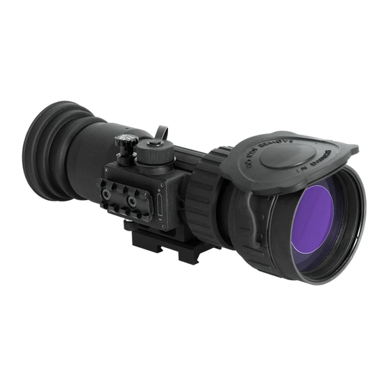
ATN PS28
NIGHT VISION CLIP-ON
ATN PS28 OPERATOR'S MANUAL (REV. 2, MAY, 2014)
o p e r a t o r ' s m a n u a l
Important Export Restrictions! Commodities, products,
technologies and services contained in this manual are
subject to one or more of the export control laws and
regulations of the U.S. Government and they fall under the
control jurisdiction of either the US Department of State
or the US BIS-Department of Commerce. It is unlawful
and strictly prohibited to export, or attempt to export or
otherwise transfer or sell any hardware or technical data
or furnish any service to any foreign person, whether
abroad or in the United States, for which a license or written
approval of the U.S. Government is required, without first
obtaining the required license or written approval from the
Department of the U.S. Government having jurisdiction.
Diversion contrary to U.S. law is prohibited.
Advertisement
Table of Contents

Related Manuals for ATN ATN PS28


Summary of Contents for ATN ATN PS28
- Page 1 ATN PS28 NIGHT VISION CLIP-ON ATN PS28 OPERATOR’S MANUAL (REV. 2, MAY, 2014) o p e r a t o r ’ s m a n u a l Important Export Restrictions! Commodities, products, technologies and services contained in this manual are subject to one or more of the export control laws and regulations of the U.S.
- Page 2 Register your product warranty online at www.atncorp.com/warranty The information in this manual is furnished for information use only, is subject to change without notice, cannot be construed as a commitment by ATN Corp. ATN Corp. assumes no responsibility or liability for any errors or inaccuracies that may appear in this book.
-
Page 3: Safety Summary
SAFETY SUMMARY CAUTIONS • The ATN PS28 is a precision optical instrument and must be handled carefully at all times to prevent damage. • Do not scratch the external lens surfaces or touch them with your fin- gers. • To protect the image intensifier, keep the lens cap on the objective lens when the sight is not in use or when checked out in daylight conditions. - Page 4 EQUIPMENT LIMITATIONS To avoid physical and equipment damage when using the ATN PS28, carefully read and understand the following equip- ment limitations. • The equipment requires some night light (moonlight, starlight, etc.) to operate. The level of equipment performance depends upon the level of light.
-
Page 5: Table Of Contents
TABLE OF CONTENTS SAFETY SUMMARY SECTION I. INTRODUCTION 1.1. General 1.1.1. Scope 1.1.2. Reports 1.1.3. Storage 1.1.4. Warranty 1.2. Description and Data 1.2.1. Description 1.2.2. Standard Components and Optional Equipment 1-8 SECTION II. OPERATING INSTRUCTIONS 2.1. Installation Procedures 2.1.1. Battery Installation 2.1.2. - Page 6 3.1. Preventive Maintenance Checks and Services (PMCS) 3.1.1. Preventive Maintenance Checks And Services Table 3.1.2. Inspection Criteria for Proper Image Intensifier Operation 3.2. Troubleshooting 3-10 3.2.1. General 3-10 3.2.2. Troubleshooting Procedures 3-10 3.3. Maintenance Procedures 3-11 3.3.1. PS28 Maintenance 3-11 3.3.2.
-
Page 7: Section I. Introduction
SECTION I INTRODUCTION... -
Page 8: General
This manual contains instructions for use in operating and main- taining the ATN PS28 Night Vision Front Sights. Throughout this manual, the ATN PS28 will be referred to as the sights or the PS28. 1.1.2. REPORTS Reports from the user on recommendations for improvements are encouraged. -
Page 9: Warranty
1.1.4. WARRANTY 2 YEAR PRODUCT WARRANTY This product is guaranteed to be free from manufacturing defects in material and workmanship under normal use for a period of 2 (two) years from the date of purchase. In the event a defect that is covered by the foregoing warranty occurs during the applicable period stated above, ATN, at its option, will either repair or replace the product, and such action on the part of ATN shall be the full extent of ATN’s liability,... - Page 10 any obligation toward any third party of legal entity outside ATN and the Customer; ATN’s obligations under this Agreement extend solely to the Customer. ATN’s liability hereunder for damages, regardless of the form or action, shall not exceed the fees or other charges paid to ATN by the customer or customer’s dealer.
-
Page 11: Description And Data
1.2. DESCRIPTION AND DATA 1.2.1. DESCRIPTION A. Purpose The PS28 is an effective night vision system that mounts forward of an existing riflescope/spotting scope (further referred to as a scope) adding night vision capabilities to daytime target acqui- sition platform. Advisable dayscope magnification is 1X to 12X (2.5X to 8X is optimum). - Page 12 • Is mounted on MIL-STD-1913 rail or dayscope lens. • Is submersible to 10 m for 30 minutes. • Filled with dry nitrogen to prevent internal fogging. D. System Limitations The PS28 is an effective night vision system designed for night op- erations but does have the following limitations: •...
- Page 13 TABLE 1-2. MECHANICAL DATA ITEM DATA Dimensions (Length x Width x Height) 7.7”x3.5”x3”/ 195x89x76 mm Weight 1.85 lbs/ 0.84 kg TABLE 1-3. ELECTRICAL DATA ITEM DATA Battery CR123A (3 V) Consumption Current: at 3.0 V 38 mA Cell Life at 20˚C: 123A Lithium Battery 36 hours TABLE 1-4.
-
Page 14: Standard Components And Optional Equipment
The PS28 standard components are shown in Figure 1-1 and pre- sented in Table 1-6. TABLE 1-6. PS28 STANDARD COMPONENTS ITEM DESCRIPTION ATN PS28 Night Vision Front Sight Objective Lens Cap Quick Release Mount (QRM) Light Suppressor Remote Control IR450-B4 IR Illuminator Kit... - Page 15 TABLE 1-7. IR450-B4 IR ILLUMINATOR KIT ITEM DESCRIPTION IR450-B4 IR 1,5 mm Allen Key IR450 Wrench Battery 123A, Lithium FIGURE 1-2. IR450-B4 IR ILLUMINATOR KIT Optional items are shown in Figure 1-3 and listed in Table 1-8. TABLE 1-8. PS28 OPTIONAL EQUIPMENT ITEM DESCRIPTION PART CODE...
- Page 16 2(3) FIGURE 1-3. PS28 OPTIONAL EQUIPMENT 1-10...
-
Page 17: Section Ii. Operating Instructions
SECTION II OPERATING INSTRUCTIONS... -
Page 18: Installation Procedures
2.1. INSTALLATION PROCEDURES 2.1.1. BATTERY INSTALLATION CAUTION Ensure the function switch is in the off position before installing a battery. Install the battery as follows: 1. Unscrew the battery compartment cap. 3. Install the battery into the battery compartment as shown. Fol- low battery symbol on the sight body (Figure 2-1). - Page 19 NOTE The optical axis of the PS28 and the riflescope should be matched. Difference of the axes position more than 3 mm is not recommended. Measure the height of the riflescope axis above the rail. Observe Table 1-2 for the sight axis height above the rail. If the difference in the axis heights of the PS28 and riflescope is more than 3 mm it is necessary to replace riflescope mounting rings or monoblock by proper ones.
-
Page 20: Attachment To Dayscope Objective Lens
MOUNT TIGHTNESS NUT WRENCH MOUNT LEVER FIGURE 2-3. QUICK RELEASE MOUNT 2.1.3. ATTACHMENT TO DAYSCOPE OBJECTIVE Scope mounting systems are designed to install the PS28 on rifle- scope/sporting scope objective lens. CAUTION The PS28 can not be attached to the riflescope/sporting scope that have a focusing ring on the objective lens housing. -
Page 21: Long Rail Adapter
RAIL FOR IR 450 FIXING NUT INSERT DAYSCOPE OBJECTIVE LENS SCOPE MOUNTING SYSTEM FIGURE 2-4. PS28 INSTALLED ON DAYSCOPE OBJECTIVE LENS 3. Insert the output lens into the scope mounting system and place the rail of the mounting system where the Quick Release Mount was above the battery compartment of the sight. -
Page 22: System
FIGURE 2-5. LONG RAIL ADAPTER INSTALLATION 5. Place the PS28 (5) onto the LRA at front of the scope. The light suppressor of the front sight should cover the riflescope objec- tive lens. 2.1.5. B.A.M. SYSTEM B.A.M. system (Boresight Attachment Mount) is used to install the PS28 Night Vision Front Sights and the dayscope on the rifles hav- ing short mounting MIL-STD-1913 rail. - Page 23 FIGURE 2-6. INSTALLATION OF B.A.M. SYSTEM 4. Install the top halves of the inserts (6) and the rings (7) and tighten each ring’s four screws (8) slightly. 5. Slightly loosen the two fixing screws (1) on the mount base (2). 6.
-
Page 24: Remote Control
10. Install the top of the mount (9) and tighten four screws (10) to finger tight. 11. Slightly loosen the two fixing screws (11) on the top rail (12). 12. Place the top rail onto the Picatinny rail on the top of the mount. -
Page 25: Ir450 Illuminator
1. Remove the rubber cap from the connector. The rubber cap can be placed onto the screw head, that attached the strap of cap to the body of device (see Figure 2-7). 2. Attach the remote control to the connector and secure with the captive nut. - Page 26 To install the battery unscrew the cap of the battery housing and insert the battery following the polarity arrows marked on the housing. Put the cap in place. The IR-450 illuminator has a control panel with two buttons. To switch the IR illuminator on/off press “+” and “-” buttons simultane- ously.
-
Page 27: Mounting Examples
2.1.8. MOUNTING EXAMPLES PS28 WITH TRIJICON ACOG PS28 WITH LEUPOLD DAYTIME SCOPE WITH B.A.M. SYSTEM AND IR450 PS28 WITH LEUPOLD DAYTIME SCOPE WITH SCOPE MOUNTING SYSTEM FIGURE 2-10. PS28 MOUNTING EXAMPLES 2.2. OPERATING PROCEDURES 2.2.1. GENERAL This section contains instructions for placing the PS-28 into op- eration. -
Page 28: Controls And Indicators
CAUTION The PS28 is a precision electro-optical instrument and must be handled carefully at all times. 2.2.2. CONTROLS AND INDICATORS LEFT SIDE VIEW MOUNT TIGHTNESS NUT REMOTE CONTROL RIGHT SIDE VIEW FUNCTION SWITCH FOCUSING RING RAIL FOR ACCESSORY CONNECTOR CAP FIGURE 2-11. -
Page 29: Operating Procedures
TABLE 2-1. PS28 CONTROLS AND INDICATORS CONTROLS FUNCTION OFF — the sight is off. Function STB — the sight is in standby mode. Switch ON — the sight is on. Switch’s spring is loaded. Focuses the input lens. Adjusts for sharpest view of Focusing Ring scene. -
Page 30: Operating With Remote Control
6. If the day-time scope has focusing rings (parallax adjustment knob), adjust focus for parallax free image. 7. If the day-time scope has reticle illumination, switch it on and adjust reticle brightness. 8. PS28 Shut-Down: a) Turn the function switch to OFF position. The green of the image intensifier tube glow will fade to black. - Page 31 (a) Turn the sight function switch to the OFF position. (b) Remove the sight from the weapon or daytime riflescope. (c) Remove attached accessories. WARNING Do not carry batteries in pockets containing metal objects such as coins, keys, etc. Metal objects can cause the batteries to short circuit and become very hot.
- Page 32 2-16...
-
Page 33: Section Iii. Maintenance Instructions
SECTION III MAINTENANCE INSTRUCTIONS... -
Page 34: Preventive Maintenance Checks And Services (Pmcs)
3.1. PREVENTIVE MAINTENANCE CHECKS AND SERVICES (PMCS) 3.1.1. PREVENTIVE MAINTENANCE CHECKS AND SERVICES TABLE A. General To ensure the readiness of the NVFS, perform the preventive main- tenance procedures in accordance with Table 2.2., prior to each mission. Preventive maintenance procedures include inspection, cleaning, and performance of the checkout procedures. - Page 35 tended mission or operation. You must do the procedure at the time stated in the interval column. (5) Not Fully Mission Capable If: Column. Information in this column tells you what faults will keep your equipment from being capable of performing its primary mission. If you make check and service procedures that show faults listed in this column, do not operate the equipment.
- Page 36 LOCATION NOT FULLY ITEM INTER- CHECK/ PROCEDURE MISSION SERVICE CAPABLE IF: Before/ Lenses Inspect for cleanliness, Chipped, cracked After scratches, chips or cracks. or if scratches hin- Clean as required. der vision through the sight Before/ Objective Check to ensure the objec- Objective lens After Lens...
- Page 37 LOCATION NOT FULLY ITEM INTER- CHECK/ PROCEDURE MISSION SERVICE CAPABLE IF: NOTE If any of the following items are damaged it does not cause the entire end item to be “not fully mission capable”. However, the damaged item should be replaced as soon as practical to restore full capability of the system.
-
Page 38: Inspection Criteria For Proper Image Intensifier Operation
3.1.2. INSPECTION CRITERIA FOR PROPER IMAGE INTENSIFIER OPERATION A. General As directed in the Preventive Maintenance Checks and Services table, image intensifier operation must be checked before each mission. This section provides information for the operator con- cerning what to look for, how to look for it, and how to determine if the NVFS should be returned to the maintainer. - Page 39 (1) Shading. If shading is present, you will not see a fully circular image (see Figure 3.1). Shading is very dark and you cannot see an image through it. Shading always begins on the edge and mi- grates inward eventually across the entire image area. Shading is a high contrast area with a distinct line of demarcation.
- Page 40 outside, 2:30 near the center, or 1:00 midway). The following are cosmetic blemishes: (1) Bright Spots. A bright spot is a small, nonuniform, bright area that may flicker or appear constant (Figure 3-3). Not all bright spots make the NVFS rejectable. Cup your hand over the objec- tive lens to block out all light.
- Page 41 (4) Fixed-Pattern Noise. This is usually a cosmetic blemish char- acterized by a faint hexagonal (honeycomb) pattern throughout the viewing area that most often occurs at high light levels or when viewing very bright lights (see Figure 3-4). This pattern can be seen in every image intensifier if the light level is high enough.
-
Page 42: Troubleshooting
3.2. TROUBLESHOOTING 3.2.1. GENERAL This section contains information for locating and removal most of the PS28 operating troubles which may occur. Each malfunction for an individual component or assembly is followed by a list of tests or inspections that will help determine probable causes and corrective action to take. -
Page 43: Maintenance Procedures
3.3. MAINTENANCE PROCEDURES 3.3.1. PS28 MAINTENANCE The PS28 maintenance consists of external inspection of its com- ponents for serviceability, cleaning and installation of the standard and optional accessories. Maintenance instructions covered else- where in this manual (PMCS, troubleshooting, etc.) are not repeat- ed in this section. - Page 44 3-12...
-
Page 45: Appendix A. How To Select Scope Mounting System
APPENDIX A HOW TO SELECT SCOPE MOUNTING SYSTEM REQUIRED FOR YOUR DAYTIME SCOPE By selecting the appropriate Scope Mounting System (with In- serts) you can mount the PS28 onto a daytime scope with an ob- jective tube diameter from 47 to 58,7 mm. At the Table 2-1 Scope Mounting System sizes (#1-2) and Insert sizes for different scope examples are provided. - Page 46 APPENDIX B ESTIMATION OF AMBIENT ILLUMINATION LEVEL Some of usual natural light conditions and corresponding repre- sentative illumination values are presented in Table B-1. TABLE B-1. STANDARD NATURAL LIGHT CONDITIONS AND ILLUMINATION VALUES STANDARD NATURAL LIGHT CONDITIONS ILLUMINATION VALUE, LUX Quarter moon 0.05 Full moon...
- Page 48 For customer service and technical support, please contact American Technologies Network Corp. 1341 San Mateo Avenue, South San Francisco, CA 94080 phone: 800-910-2862, 650-989-5100; fax: 650-875-0129 www.atncorp.com ©2014 ATN Corporation...