Table of Contents
Advertisement
Quick Links
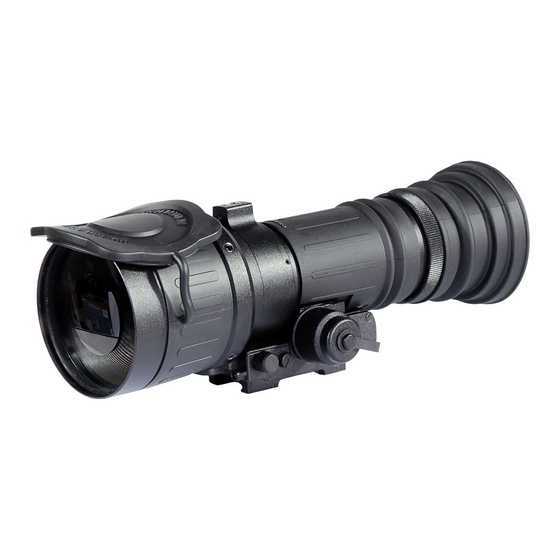
ATN PS-40
ATN PS-40 MGC
NIGHT VISION FRONT SIGHTS
ATN PS-40/ ATN PS-40 MGC
oPerATor'S MANUAl (rev. 3, AUGUST 2010)
o p e r a t o r ' s m a n u a l
Important Export Restrictions! Commodities, products,
technologies and services contained in this manual are
subject to one or more of the export control laws and
regulations of the U.S. Government and they fall under the
control jurisdiction of either the US Department of State
or the US BIS-Department of Commerce. It is unlawful
and strictly prohibited to export, or attempt to export or
otherwise transfer or sell any hardware or technical data
or furnish any service to any foreign person, whether
abroad or in the United States, for which a license or written
approval of the U.S. Government is required, without first
obtaining the required license or written approval from the
Department of the U.S. Government having jurisdiction.
Diversion contrary to U.S. law is prohibited.
Advertisement
Table of Contents

Related Manuals for ATN PS-40


Summary of Contents for ATN PS-40
- Page 1 ATN PS-40 ATN PS-40 MGC NIGHT VISION FRONT SIGHTS ATN PS-40/ ATN PS-40 MGC oPerATor’S MANUAl (rev. 3, AUGUST 2010) o p e r a t o r ’ s m a n u a l Important Export Restrictions! Commodities, products,...
- Page 2 The information in this manual is furnished for information use only, is subject to change without notice, cannot be construed as a commitment by ATN Corp. ATN Corp. assumes no responsibility or liability for any errors or inaccuracies that may appear in this book.
- Page 3 STUDY CAREFULLY THIS MANUAL BEFORE TURNING ON AND OPERATING THIS PRODUCT. CAUTIONS The ATN PS-40 night vision unit is a precision electron-optical instrument and requires careful handling. To provide safe use of the sight the following instructions should be observed: •...
- Page 4 EqUIPMENT LIMITATIONS To avoid physical and equipment damage when using the ATN PS-40, carefully read and understand the following equip- ment limitations. • The equipment requires some night light (moonlight, starlight, etc.) to operate. The level of equipment performance depends upon the level of light.
-
Page 5: Table Of Contents
1.1.1. Scope 1.1.2. reports 1.1.3. Storage 1.1.4. Warranty 1.2. Description and Data 1.2.1. Description 1.2.2. PS-40 Standard Components and optional equipment SECTION II. OPERATING INSTRUCTIONS 2.1. Installation Procedures 2.1.1. Battery Installation 2.1.2. Installation on MIl-STD-1913 rail 2.1.3. Installation on Dayscope objective lens 2.2. - Page 6 4.1.2. PMCS Procedures 4.2. Troubleshooting 4.2.1. General 4.2.2. Troubleshooting Procedures 4.3. Maintenance Procedures 4.3.1. Scope of PS-40 Maintenance 4.3.2. Cleaning Procedures Appendix A. Spare Parts List Appendix B. How to select Scope Mounting System Appendix C. Estimation of Ambient Illumination Level C-1 Appendix D.
-
Page 7: Section I. Introduction
SECTION I INTRODUCTION... -
Page 8: General
This will ensure the sight remains in mission ready condition dur- ing storage. Battery should be stored separately from the sight. The PS-40 should not be placed on the floor, in any area exposed to high temperatures or direct sunlight. Presence of acid and al- kaline vapor, as well as of other aggressive admixtures in the air is unacceptable. -
Page 9: Warranty
ATN, at its option, will either repair or replace the product, and such action on the part of ATN shall be the full extent of ATN’s liability, and the Customer’s sole and exclusive remedy. This warranty does not cover a product (a) used in other than its normal and customary man- ner;... - Page 10 Customer. ATN’s liability hereunder for damages, regardless of the form or action, shall not exceed the fees or other charges paid to ATN by the customer or customer’s dealer. ATN shall not, in any event, be liable for special, indirect, incidental, or consequential damages, including, but not limited...
-
Page 11: Description And Data
1.2. DESCRIPTION AND DATA 1.2.1. DESCRIPTION A. Purpose The PS-40 is an effective night vision system that mounts forward of an existing riflescope/spotting scope (further referred to as a scope) adding night vision capabilities to daytime target acqui- sition platform. Advisable dayscope magnification is 1X to 12X (2.5X to 8X is optimum). - Page 12 • Is submersible to 10 m for 30 minutes. • Filled with dry nitrogen to prevent internal fogging. The PS-40 is an effective night vision system designed for night operations but does have following limitations: • The sight requires some night light (moonlight, starlight, etc.) to operate.
- Page 13 TABLE 1-2. MECHANICAL DATA ITEM DATA Dimensions (Length x Width x Height) 177 x 85 x 83 mm Weight: without Battery 0.84 kg with remote Control, light Suppressor 0.91 kg and Battery Height of the Sight Axis above Arm Rail: with Quick release Mount 41.3 mm with Weaver Mount...
-
Page 14: Standard Components And Optional Equipment
Natural night illumination (overcast star- light to moonlight) Immersion 10 m for 30 minutes 1.2.2. PS-40 STANDARD COMPONENTS AND OPTIONAL EqUIPMENT The PS-40 standard components are shown in Figure 1-1 and pre- sented in Table 1-6. FIGURE 1-1. PS-40 STANDARD COMPONENTS... - Page 15 TABLE 1-6. PS-40 STANDARD COMPONENTS ITEM DESCRIPTION ATN PS-40/PS-40 MGC Night vision Front Sight objective lens Cap Quick release Mount (QrM) output lens Cap light Suppressor remote Control IR450-B4 IR Illuminator Kit Platform ring Shipping /Storage Case Battery 123A, lithium 2.5 mm Allen Key...
- Page 16 Figure 1-3 and listed in Table 1-8. 3(4) FIGURE 1-3. PS-40 OPTIONAL EqUIPMENT TABLE 1-8. PS-40 OPTIONAL EqUIPMENT ITEM DESCRIPTION PART CODE Adapter for A.r.M.S. Mounts CoWSPSAM ACDNPS40MWvr Weaver Mount ACDNPS40SM01 Scope Mounting System #1...
-
Page 17: Section Ii. Operating Instructions
SECTION II OPERATING INSTRUCTIONS... -
Page 18: Installation Procedures
2.1. INSTALLATION PROCEDURES 2.1.1. BATTERY INSTALLATION CAUTION Ensure the function switch is in the off position before installing a battery. Install the battery as follows: 1. observe Figure 2-1 for right position of the threaded insert ac- cording to the battery to be installed. 2. -
Page 19: Installation On Mil-Std-1913 Rail
Measure the height of the riflescope axis above the rail. Observe Table 1-2 for the sight axis height above the rail. If the difference in the axis heights of the PS-40 and riflescope is more than 3 mm it is necessary to replace riflescope mounting rings or monoblock by proper ones. -
Page 20: Installation On Dayscope Objective Lens
2.1.3. INSTALLATION ON DAYSCOPE OBjECTIVE LENS Presented in Table 2-1 optional scope mounting systems are de- signed to install the PS-40 on riflescope/sporting scope objective lens. The systems are equipped with a rail for mounting optional Ir illuminator. TABLE 2-1. SCOPE MOUNTING SYSTEMS... - Page 21 To choose the system # and insert refer to the Table 2-1. For example, the scope mounting system #1 and 47 mm insert are necessary to mount the PS-40 on leupold 3.5-10x40 riflescope. NOTE Optical axes of the PS-40 and the riflescope should be matched.
- Page 22 M4x8 and tighten it. 5. loosen the nut of the mounting system. 6. Slide the PS-40 with mounting system onto the objective lens of dayscope up to the stop. 7. To complete the installation of the mounting system to your day- scope, use a screw driver to tighten the nut of the mounting sys- tem.
-
Page 23: Operating Procedures
2.2. OPERATING PROCEDURES 2.2.1. GENERAL This section contains instructions for placing the PS-40 into opera- tion. The function of controls is explained. CAUTION The PS-40 is a precision electro-optical instrument and must be handled carefully at all times. 2.2.2. CONTROLS AND INDICATORS... -
Page 24: Operating Procedures
2.2.3. OPERATING PROCEDURES These procedures should be performed under night light condi- tions only. CAUTION Use of the PS-40 under high light conditions may damage the image intensifier. 1. Make sure the battery is installed as indicated on the sight body. - Page 25 CAUTION Bright sources such as light of fire, headlights, searchlights, etc. can damage the PS-40. Avoid exposing the PS-40 to these types light sources. 6. Adjust image tube brightness using the gain control knob (MGC version of the sight) to achieve the best possible image contrast.
-
Page 26: Operating At Changing Light Condition
2.2.4. OPERATING AT CHANGING LIGHT CONDITIONS The sight has a protection system, which cuts off the image inten- sifier when ambient light level exceeds the limit of 40 lux during 10 seconds. If a mission has to be carrying out at changing light conditions, it is possible to shut down the protection system with the following procedure: take off the rubber cap from remote switch connector and put it onto the light sensor. -
Page 27: Stowage Of
2.2.6. STOwAGE OF PS-40 1. ensure the PS-40 and all accessories are clean and dry before returning to storage case. 2. replace the objective cap and output cap on the lenses. re- move the battery. 3. Make sure the sight and accessories are stored in the appropri- ate locations in the case and close the cover. -
Page 28: Installation And Use Of Accessories
2.3. INSTALLATION AND USE OF ACCESSORIES 2.3.1. 7/8” wEAVER MOUNT optional Weaver mount can be used to install the PS-40 on a MIl- STD-1913 rail if mounting rail on the rifle has narrow groves (4 mm). WeAver MoUNT M4X8 SCreW ClAMP BAr FIGURE 2-10. -
Page 29: Adapter For A.r.m.s. Mounts
PS-40 in short-time activation mode. Attach the remote control to the PS-40 and use it as follows: 1. remove the rubber cap from the connector. The rubber cap can be placed onto the screw head, that attached the strap of cap to the body of device (see Figure 2-12 ). -
Page 30: Platform Ring
CoNNeCTor FIGURE 2-12. REMOTE CONTROL 2.3.4. PLATFORM RING If the PS-40 is installed on MIl-STD-1913 rail, optional Platform ring is used for mounting optional Ir illuminator on dayscope hav- ing mounting diameter 25.4 or 30 mm (Figure 2-3). Attach the Platform ring to dayscope as follows (Figure 2-13): FIGURE 2-13. -
Page 31: Long Rail Adapter
(Figure 2-3). 2.3.6. B.A.M. SYSTEM optional B.A.M. system (Boresight Attachment Mount) is used to install the PS-40 and dayscope on the rifles having short mounting MIl-STD-1913 rail. There are three advantages of the system: • Low position of the sight and dayscope (36 mm above the rail). - Page 32 8. Slightly loosen the two fixing screws [11] on the top rail [12]. 9. Place the top rail onto the Picatinny rail on the top of the mount. 10. Tighten the fixing screws of the top rail. 11. Place the Night vision Front Sight [13] onto the top rail at front of the scope.
-
Page 33: Ir450 Illuminator
2.3.7. IR450 ILLUMINATOR Ir450-B4 illuminator provides the capability for operator to use the PS-40 under extremely low light conditions and in total dark- ness. The Ir illuminator can be mounted on rail of the Platform ring, or of the Scope Mounting System (Figure 2-15), or on top rail of the B.A.M. - Page 34 The ATN Ir450 is powered with one Cr123A lithium battery. To in- stall the battery unscrew the cap of the battery housing and insert the battery following the polarity arrows marked on the housing. Put the cap in place. The Ir-450 illuminator has a control panel with two buttons. To switch the IR illuminator on/off press “+”...
-
Page 35: Day Scope Light Suppressor
2.3.8. DAY SCOPE LIGHT SUPPRESSOR To maximize usage of the PS-40 with a daytime scope a rubber light suppressor (DSlS) is included. The DSlS slides over the eyepiece of your daytime scope. The DSlS was designed to achieve several missions: 1. - Page 36 To install the Extender Focus Knob (Figure 2-19): 1. Unscrew the fixing screw. replace it to short fixing screw [1] from extender Focus Knob Kit. Screw the new fixing screw [1] to the lug and tighten it. Do not over tight it avoiding irregular rotation of the focus ring.
-
Page 37: Section Iii. Operational Defects
SECTION III OPERATIONAL DEFECTS... -
Page 38: Zeroing Operational Defects
Their identification shall be a valid reason to immediately refuse to accept the ATN PS-40. These include shading, edge glow, flashing, flickering, and inter- mittent operation. -
Page 39: Edge Glow
However, some types of blemishes can get worse over time and interfere with the usabil- ity of the device. If you believe a blemish is a cause for rejection, warranty or repair please ATN or point of purchase for warranty/ repair procedures. - Page 40 A bright spot is a small, non-uniform, bright area that may flicker or appear constant (Figure 3-3). Not all bright spots make the ATN PS-40 rejectable. Cup your hand over the lenses to block out all light. If the bright spot re- mains, return the ATN PS-40.
- Page 41 C. Black Spots These are cosmetic blemishes in the image intensifiers or dirt or debris between the lenses. Black spots are acceptable as long as they do not interfere with viewing the image. No action is re- quired if this condition is present unless the spots interfere with the usability of the device.
- Page 42 E. Chicken wire. An irregular pattern of dark thin lines in the field of view either throughout the image area or in parts of the image area (Figure 3-5). Under the worst-case condition, these lines will form hex- agonal or square-wave shaped lines. This is typically viewed in high light conditions.
-
Page 43: Section Iv. Maintenance Instructions
SECTION IV MAINTENANCE INSTRUCTIONS... -
Page 44: Preventive Maintenance Checks And Services (Pmcs)
PMCS is performed daily when in use to be sure that the sight is ready at all times. Procedures listed in Table 4-1 are a systematic inspection of the PS-40 that will enable you to discover defects that might cause the sight to fail on a mission. - Page 45 TABLE 4-1. PREVENTIVE MAINTENANCE CHECKS AND SERVICES SEq. ITEM TO NOT FULLY MISSION CHECKING PROCEDURE CHECK CAPABLE IF: Inspect for cleanliness, Chipped, cracked or if lenses scratches, chips or cracks. scratches hinder vision Clean as required. through the sight. objective Check to ensure the objec- objective lens loose.
- Page 46 CHECK CAPABLE IF: OPERATIONAL CHECKS CAUTION: Activate the PS-40 in daylight with objective lens cap on or low light conditions. NOTES: 1. PMCS checks for daylight conditions are listed below. 2. when looking through the PS-40 with objective lens cap on, observable image has a form of two overlapping zones.
- Page 47 TABLE 4-1. PREVENTIVE MAINTENANCE CHECKS AND SERVICES SEq. ITEM TO NOT FULLY MISSION CHECKING PROCEDURE CHECK CAPABLE IF: Check for flickering, flash- ing, bright spots, edge e xcessive cosmetic viewed Im- glow, shading, excessive defects or fixed pattern fixed-pattern noise (hon- noise.
-
Page 48: Troubleshooting
4.2.1. GENERAL This section contains information for locating and removal most of the PS-40 operating troubles which may occur. each malfunction for an individual component or assembly is followed by a list of tests or inspections that will help determine probable causes and corrective action to take. - Page 49 TABLE 4-2. TROUBLESHOOTING PROCEDURES PROBLEM PROBABLE CAUSE CORRECTIVE ACTION objective and output Clean thoroughly the lenses Cannot achieve lenses dirty. surfaces. the sharp image of the object. 1. Using hex wrench tighten M3x6 screw which secures driving ring on threaded ring.
- Page 50 TABLE 4-2. TROUBLESHOOTING PROCEDURES PROBLEM PROBABLE CAUSE CORRECTIVE ACTION Sight affects Send the sight to the ser- objective lens loose. boresight after vice center. installation or Factory alignment bro- Send the sight to the ser- during the firing. ken. vice center. THREADED RING DrIvING rING LoCKING RING...
-
Page 51: Maintenance Procedures
4.3. MAINTENANCE PROCEDURES 4.3.1. PS-40 MAINTENANCE The PS-40 maintenance consists of external inspection of its components for serviceability, cleaning and installation of the standard and optional accessories. Maintenance instructions covered else-where in this manual (PMCS, troubleshooting, etc.) are not repeated in this section. - Page 52 Spare Parts list. The amount and assortment of the spare parts needed should be arranged with each contract individually. TABLE A-1. ATN PS-40 SPARE PARTS LIST PART NO. DESCRIPTION FIG. ITEM AT 146551.700...
- Page 53 TABLE A-1. ATN PS-40 SPARE PARTS LIST PART NO. DESCRIPTION FIG. ITEM AT 146552.704 Storage/Shipping Case AT 146552.750 2.5 mm Allen Wrench AT 146552.705 operator's Manual AT 146553.700 Accessories 2 (Optional) AT 146553.701 Adapter for A.r.M.S. Mount AT 146553.702 7/8” Weaver Mount AT 146553.704...
- Page 54 FIGURE A-2. ACCESSORIES 1 (FROM THE KIT) 3(4) FIGURE A-3. ACCESSORIES 2 (OPTIONAL)
-
Page 55: Appendix B. How To Select Scope Mounting System
REqUIRED FOR YOUR DAYTIME SCOPE By selecting the appropriate Scope Mounting System (with In- serts) you can mount the PS-40 onto a daytime scope with an ob- jective tube diameter from 47 to 58,7 mm. At the Table 2-1 Scope Mounting System sizes (#1-2) and Insert sizes for different scope examples are provided. - Page 56 APPENDIx C ESTIMATION OF AMBIENT ILLUMINATION LEVEL Some of usual natural light conditions and corresponding repre- sentative illumination values are presented in Table C-1. TABLE C-1. STANDARD NATURAL LIGHT CONDITIONS AND ILLUMINATION VALUES STANDARD NATURAL LIGHT CONDITIONS ILLUMINATION VALUE, LUx Quarter moon 0.05 Full moon...
-
Page 57: Appendix D. Night Vision Front Sights Image Intensifier Tube Replacement Manual
A. Tools Next tools are necessary for this procedure: • Lock-ring spanner wrench • Purge kit B. Equipment Table D-1 lists requirements for the equipment needed for PS-40 focusing and aligning after tube replacement. TABLE D-1. NEEDED EqUIPMENT ITEM # ITEM... - Page 58 FIGURE D-1. VARIABLE GAIN TUBE REPLACEMENT FIGURE D-2. CONSTANT GAIN TUBE REPLACEMENT FIGURE D-3. INSTALLATION OF THE BOARD TO THE VARIABLE FIGURE D-4. ADjUSTMENT RING GAIN TUBE...
- Page 59 D-2. TUBE REMOVAL - loosen four objective adjustment screws (Figure D-1, 6). - Unscrew the lock ring (Figure D-1, 2). - remove the objective lens (Figure D-1, 1). - Unscrew the lock ring (Figure D-1, 7). - Draw out the orienting sleeve (Figure D-1, 9). - Take off defective image intensifier tube.
- Page 60 TABLE D-2. ADjUSTING SHIMS TUBE LENGTH NUMBER OF SHIMS 29.7 to 30.2 30.2 to 30.7 30.7 to 31.2 - If additional shims are necessary cut it from cardboard, texto- lite or fiberglass plastic. The thickness of material is 0.5 mm. - Put the shims on the bottom of the tube compartment.
- Page 61 Attenuator filter have to be neutral glass filter with density 4 to 5. The filter effective diameter should be 63 mm and sur- face parallelism within 1 MOA. It is installed in the housing to mount on the sight. D-4. EqUIPMENT PREPARING - Provide coaxial position of the collimator, the sight and the telescope.
- Page 62 - If sharp image has not been achieved slightly loose the fix screw, rotate the driving ring to the middle position, tighten the screw and repeat focusing. D-6. OUTPUT LENS FOCUSING - Carefully separate the rubber cover (Figure D-1, 3) from the sight body and remove it.
- Page 63 D-7. BORESIGHT ALIGNMENT - Switch the collimator pattern illuminator on in daytime mode. - Without the sight, looking through the telescope check match- ing it’s crosshair with collimator crosshair. - Switch the collimator pattern illuminator on in nighttime mode. - Put the sight onto the mounting rail, switch it on and rotate focus ring to achieve sharp image.
- Page 64 800-910-2862, 650-989-5100; fax: 650-875-0129 European Office The following countries can use our toll free number: 00 800 9102-8620 Austria, France, Germany, Holland, Italy, Spain, Sweden, Switzerland For other countries, please use 38 048-7770214 or 38 048-7770345 www.atncorp.com ©2010 ATN Corporation...