Table of Contents
Advertisement
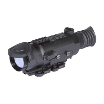
ATN ThOR Series
THERMAL OPTICAL RIFLESCOPES
Thor SerIeS operaTor'S manUal (rev. 3, December 2010)
o p e r a t o r ' s m a n u a l
I m p o r t a n t E x p o r t R e s t r i c t i o n s ! T h e p r o d u c t s ,
technologies and services contained in this manual are
subject to one or more export control laws and regulations
of the U.S. Government and they fall under the control
jurisdiction of the US Department of State. It is unlawful
and strictly prohibited to export, or attempt to export or
otherwise transfer or sell any hardware or technical data or
furnish any service to any foreign person, whether abroad or
in the United States, for which a license or written approval
of the U.S. Government is required, without first obtaining
the required license or written approval from the appropriate
Department of the U.S. Government having jurisdiction in
such matters. Diversion contrary to U.S. law is prohibited.
Advertisement
Table of Contents

Related Manuals for ATN ThOR Series


Summary of Contents for ATN ThOR Series
- Page 1 ATN ThOR Series THERMAL OPTICAL RIFLESCOPES Thor SerIeS operaTor’S manUal (rev. 3, December 2010) o p e r a t o r ’ s m a n u a l I m p o r t a n t E x p o r t R e s t r i c t i o n s ! T h e p r o d u c t s ,...
- Page 2 /warranty The information in this manual furnished for information use only, is subject to change without notice, is not to be construed as a commitment by aTn corp. aTn corp. assumes no responsibility or liability for any errors or inaccura- cies that may appear in this book.
- Page 3 SAFETY SUMMARY STUDY CAREFULLY THIS MANUAL BEFORE TURNING ON AND OPERATING THIS PRODUCT. CAUTIONS The ATN ThOR Series Thermal Optical Riflescopes are preci- sion electro-optical instruments and requires careful han- dling. To provide safe use of the systems the following instructions should be observed: •...
- Page 4 (such as the sun or a welding arc). If you do, you will damage the scope. wARNING Operating ThOR Series outside of its specified operating tem- perature range or voltage range can cause permanent damage and will void the warranty.
- Page 5 Observe battery manufacturer’s guidelines for safe handling and proper disposal of batteries. EqUIPMENT LIMITATIONS • The ThOR Series detector spectral band (7 to 14 mkm) pro- vides a better penetration through smoke, smog, dust, water vapor etc. • Infrared radiation does not travel through glass and therefore the scope does not sense objects if they are behind a glass window.
-
Page 6: Table Of Contents
TABLE OF CONTENTS SECTION I. INTRODUCTION 1.1 General Information 1.1.1. Scope 1.1.2. reports 1.1.3. Storage 1.1.4. Warranty Information 1.2. Description and Data 1.2.1. Description 1.2.2. ThOR Standard Components 1.2.3. Thor optional components 1.2.4. Specifications 1.2.5. mechanical Functions 1-11 1.2.6. optical Functions 1-12 1.2.7. - Page 7 3.2.3. polarity 3.2.4. Brightness 3.2.5. Zoom 3.2.6. manual Image refresh 3.2.7. Reticle Color/Brightness Adjustment 3.2.8. Windage and Elevation 3.2.9. Shut Down operations SECTION IV. MAINTENANCE INSTRUCTIONS 4.1. Preventive Maintenance Checks and Services (PMCS) 4.1.1. Purpose of PMCS 4.1.2. Frequency of Performing PMCS 4.2.
-
Page 9: Section I. Introduction
SECTION I INTRODUCTION... -
Page 10: General Information
1.1.1. SCOPE This manual contains instructions for use in operating and main- taining the aTn Thor Series Thermal optical riflescopes. Throughout this manual, the aTn Thor Series will be referred to as the scope or Thor. 1.1.2. REPORTS reports from the user on recommendations for improvements are encouraged. -
Page 11: Warranty Information
remedy. - Page 12 (RMA). When returning please take or send the product, postage paid, with a copy of your sales receipt to our service center, aTn corpora- tion at the address noted above. all merchandise must be fully insured with the correct postage;...
-
Page 13: Description And Data
1.2. DESCRIPTION AND DATA 1.2.1. DESCRIPTION A. Purpose. The Thor Series Thermal optical riflescopes combines the er- gonomic features of a handheld and the convenience of weapon mounting. Based on the proven 320 x 240 microbolometer core, the Thor is an ideal product for force protection, border patrol... - Page 14 B. Features. Thor has the following important features: • High resolution digital thermal imaging • Compact, lightweight and durable housing • True magnification • High end OLED display • Two-colors reticle system • Rapid start-up in 3 seconds • Up to 6 hours operation with four lithium batteries •...
-
Page 15: Thor Standard Components
1.2.2. ThOR STANDARD COMPONENTS The Thor standard components are shown in Figure 1-3 and presented in Table 1-1. FIGURE 1-3. THOR STANDARD COMPONENTS TABLE 1-1. THOR STANDARD COMPONENTS ITEM DESCRIPTION Scope Quick release mount hard Storage case lens Tissue lithium battery cr123a rca video/power adapter operator’s manual Scope... -
Page 16: Thor Optional Components
4) Lens Tissue Uses for cleaning of lenses surface. 5) Lithium Battery CR123A Four cr123a lithium batteries used to power the unit. 6) RCA Video/power adapter rca video/power adapter used for video transmission and to connect external power sources. 7) Operators Manual provides equipment description, use of operator controls and preventative maintenance checks and service. -
Page 17: Specifications
1.2.4. SPECIFICATIONS The following tables provide information pertaining to the opera- tional, electrical, mechanical, optical and environmental character- istics for the sights. TABLE 1-3. SPECIFICATIONS THOR-2x THOR-3x Sensor (microbolometer) 320x240 Type Uncooled 30hz Image Size (output resolution) NTSC: 640x480 30hz video output nTSc Display... - Page 18 Dimensions, inches (with bracket) 8.5x3.0x3.5 10.2x3.0x3.5 mounting bracket Quick release picatinny external power 9 - 12v Dc other options video output video in low battery Indicator * aTn reserves the right to change the above specifications at any time without notice 1-10...
-
Page 19: Mechanical Functions
1.2.5. MECHANICAL FUNCTION The mechanical adjustments of the Thor sights allow for physi- cal differences between individual operators using the system. The scope functions include the switchboard, refresh button, universal connector, eyepiece diopter adjustment ring, focusing ring, battery compartment cover, mounting rail. The mechanical controls are identified in Figure 1-5. -
Page 20: Optical Functions
1.2.6. OPTICAL FUNCTION The optical functions include an objective lens, thermal imaging detector, display and eyepiece. Infrared energy is emitted propor- tionally to the temperature of an object. The warmer the object, the more energy it emits. The infrared energy from the objects is fo- cused by the optics, onto an infrared detector. -
Page 21: Section Ii. Assembly And Preparation
SECTION II ASSEMBLY AND PREPARATION... -
Page 22: Preparation
2.1. PREPARATION 2.1.1. PREPARATION FOR USE This chapter contains the information necessary to prepare the scope for operation. This includes unpacking, examination for da- mage, and batteries installation. A. Unpacking. The following steps must be accomplished prior to each mission where the sight is used. -
Page 23: Examination For Operation
FIGURE 2-1. INSTALL BATTERIES 2.1.2. ExAMINATION FOR OPERATION before getting started make sure to follow these steps: 1. push on/oFF button on the scope. 2. make sure that the luminance in ocular is present. 3. observe the scene, and adjust the diopter and/or lens for opti- mal image clarity. -
Page 24: Assembly
2.2. ASSEMBLY 2.2.1. REMOVE/INSTALLATION OF qUICk RELEASE MOUNT (qRM) aTn Double lever Quick release mount (Qrm) is used for fast installation/removing the Thor on mIl-STD-1913/picatinny rail. moUnTInG SCREWS FIGURE 2-2. DOUBLE LEVER qUICk RELEASE MOUNT cloSeD poSITIon openeD poSITIon FIGURE 2-3. DOUBLE LEVER qUICk RELEASE MOUNT ADjUSTMENT 1. -
Page 25: Video Output
5. The shoes can also be adjusted for different mounting positions. To remove shoe unscrew the two screws (4) and place shoe in desired position. 6. place the scope onto rail. be sure to engage the recoil lug into the groove on the top mounting surface of the rifle. 7. -
Page 26: External Power Source
2.2.3. ExTERNAL POwER SOURCE wARNING when the unit is to be powered with external sources, first make sure the batteries have been taken out. as an external power source, a standard ac controller with outer voltage of 12v and current of over 2a can be applied. To connect an external source recommend to use a 6 mm standard double-pole socket in the way the positive contact is the central contact. - Page 27 FIGURE 2-7. INSTALLATION ONTO THE ATN THOR 1. Place the DVC onto ThOR rail (Figure 2-7). Be sure to engage the recoil lug into the groove on the mounting surface. NOTE Operations with qRM of DVC are similar to the operations with qRM described in Unit 2.2.1.
-
Page 29: Section Iii. Operation
SECTION III OPERATION... -
Page 30: General Information
3.1. GENERAL INFORMATION 3.1.1. GENERAL This section contains instructions for operation of Thor. The func- tion of controls and indicators is explained. CAUTION The ThOR scope is a precision electron-optical instrument and must be handled carefully at all times. 3.1.2. CONTROLS AND INDICATION The Thor scope is designed to adjust for different users and cor- rects for most differences. - Page 31 TABLE 3-1. CONTROLS AND INDICATION CONTROLS AND ITEMS FUNCTIONS INDICATORS on/oFF button controls scope power. To turn the unit on and off press the button . brIGhTneSS adjustment of the output image brightness. buttons POLARITY Switch from hot-white/cold-black into hot- button black/cold-white mode (only in black and White mode).
-
Page 32: Operating Procedure
During the warm-up time, a logo comes into view on the mono- cular display. Next the thermal image replaces the logo. on/oFF bUTTon FIGURE 3-2. SwITCHBOARD OF ATN THOR 3.2.2. FOCUSING To focus the scope you need to adjust the diopter first. The scope has an adjustable eyepiece with a range of + 5 to -5 diopter. -
Page 33: Polarity
You scope has ability to focus either long range or short. Focus the front lens to rotate it until the image and the grain are both sharp. FocUSInG rInG EYEPIECE DIOPTER aDJUSTmenT rInG FIGURE 3-3. FOCUS ADjUSTMENT NOTE The front lens should be readjusted for viewing objects at diffe- rent distances. -
Page 34: Brightness
3.2.4. BRIGHTNESS press brIGhTneSS + and brIGhTneSS – buttons for bright- ness adjustment. each short push of the buttons brIGhTneSS + or brIGhTneSS – raises or lowers the display brightness, cor- respondingly, in stepwise way. NOTE Levels 1 to 8 range from full dim to full bright. 3.2.5. -
Page 35: Reticle Color/Brightness Adjustment
3.2.7. RETICLE COLOR/BRIGHTNESS ADjUSTMENT Your scope has a reticle with two color and 5 degrees of bright- ness of illumination for each color. The knob of brightness adjust- ment reticle and color select is located on the side of the body of the scope. -
Page 36: Shut Down Operations
3.2.9. SHUT DOwN OPERATIONS To finish the work, perform the following: 1. Use the on/oFF button to turn the scope off. 2. replace the protective cover on the objective lens. 3. Disconnect the cable (if present). replace the protective cap on the scope output connector socket. -
Page 37: Section Iv. Maintenance Instructions
SECTION IV MAINTENANCE INSTRUCTIONS... -
Page 38: Preventive Maintenance Checks And Services (Pmcs)
4.1. PREVENTIVE MAINTENANCE CHECkS AND SERVICES (PMCS) 4.1.1. PURPOSE OF PMCS pmcS is performed daily when in use to be sure that the sight is ready at all times. Procedures listed in Table 4-1 are a systematic inspection of Thor that will enable you to discover defects that might cause the sight to fail on a mission. - Page 39 SEq. ITEM TO NOT FULLY MISSION CHECkING PROCEDURE CHECk CAPABLE IF: objective check to ensure the objec- objective lens loose. lens tive lens is not loose. check to ensure: Focus ring able to — the focus ring cannot be move along sight Focus moved along the sight body;...
-
Page 40: Troubleshooting
4.2. TROUBLESHOOTING 4.2.1. GENERAL This section contains information for locating and removal most of the Thor operating troubles which may occur. each malfunction for an individual component or assembly is followed by a list of tests or inspections that will help determine probable causes and corrective action to take. -
Page 41: Maintenance Procedures
4.3. MAINTENANCE PROCEDURES 4.3.1. SCOPE MAINTENANCE The Thor maintenance consists of external inspection of its com- ponents for serviceability, cleaning and installation of the stan- dard and optional accessories. maintenance instructions covered elsewhere in this manual (pmcS, troubleshooting, etc.) are not repeated in this section. -
Page 42: Preparing For Extended Storage
4.3.3. PREPARING FOR ExTENDED STORAGE To prepare the Thor for extended storage, perform the follow- ing: 1. Check the scope for serviceability as outlined in item 4.1 of this manual. 2. remove the batteries. 3. clean the scope and accessories. 4. - Page 44 800-910-2862, 650-989-5100; fax: 650-875-0129 European Office The following countries can use our toll free number: 00 800 9102-8620 austria, France, Germany, holland, Italy, Spain, Sweden, Switzerland For other countries, please use 38 048-7770214 or 38 048-7770345 www.atncorp.com ©2010 aTn corporation...