Table of Contents
Advertisement
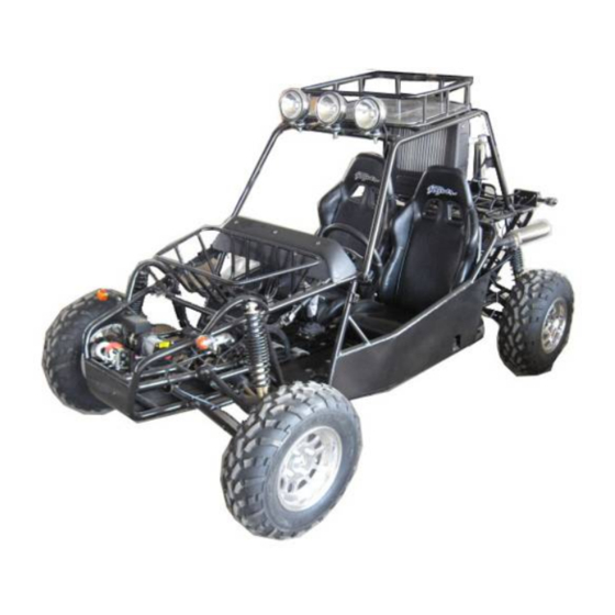
Owner's manual
Parts manual
READ THIS MANUAL CAREFULLY.
IT CONTAINS IMPORTANT SAFETY
MINIMUM
RECOMMENDED
OPERATOR AGE
FOR OFF-ROAD USE ONLY
This vehicle is designed and manufactured for off-road use only.
USA only;
It does not confirm to federal motor vehicle safety standards, and
operation on public streets, roads, or highways is illegal.
.
JNSZ650DLB
Advertisement
Table of Contents

Related Manuals for Joyner JNSZ650DLB


Summary of Contents for Joyner JNSZ650DLB
-
Page 1: Parts Manual
Owner’s manual JNSZ650DLB Parts manual READ THIS MANUAL CAREFULLY. IT CONTAINS IMPORTANT SAFETY MINIMUM RECOMMENDED OPERATOR AGE FOR OFF-ROAD USE ONLY This vehicle is designed and manufactured for off-road use only. USA only; It does not confirm to federal motor vehicle safety standards, and... -
Page 2: Table Of Contents
CONTENTS WARRANTY POLICY ..............................5 OWNER’S MANUAL ..............................16 ................................16 OREWORD ............................ 17 OREWORD ABOUT SAFETY .......................... 18 MPORTANT SAFETY INFORMATION Follow the Age Recommendation ........................18 Always Wear a Helmet ............................18 Drive Off-Road Only .............................. 18 Take Time to Learn & Practice ..........................18 Be Alert for Off-Road Hazards .......................... - Page 3 Keep Hands and Feet on Controls ........................25 Control Speed ................................ 25 Use Care on Unfamiliar or Rough Terrain ......................26 Do Not Perform Stunts ............................26 ..............................27 PECIFICATIONS ................................28 PERATION Operation controls ..............................28 Engine stop key ..............................30 Pre-Drive Inspection .............................
- Page 4 WATER PUMP AND FAN PART ........................72 DISTRIBUTOR AND ITS LINE UNIT ........................73 CARBURETOR PART ............................74 AIR FILTER AND PIPE LINE PART ........................75 STARTER , ALTERNATOR AND THEIR FASTENING PIECE ..............76 TRANSMISSION TANK ............................77 CLUTCH, SHIFTER SHAFT AND ROCKER ARM ..................79 DIFFERENTIAL ..............................
- Page 5 ........................131 TTACH THE REAR SUSPENSION ARM ....................132 TTACH PROPELLER SHAFT AND SHAFT CARRIER ATTACH REAR SHOCK ABSORBER AND REAR WHEEL ................134 .................... 135 TTACH REAR SHOCK ABSORBER AND REAR WHEEL ..........................136 TTACH REAR BUMPER BAR ..............................137 TTACH ROLL BAR ..........................
-
Page 6: Warranty Policy
Warranty policy... -
Page 17: Owner's Manual
Owner’s manual Foreword Thank you for choosing JOYNER off Highway Recreational Vehicle. We hope you will have fun with it. Before you start to operate the Vehicle, please read through this Owner’s Manual carefully as it contains important safety and maintenance information. Failure to follow the warnings contained in this manual can result in serious injuries. -
Page 18: Foreword About Safety
Foreword about safety In order to keep everyone safe, you must take responsibility for the safe operation of your Off Highway Recreational Vehicles. To help you make informed decisions about safety, we have provided operating procedures and other information on labels and in this manual. This information alerts you to potential hazards that could hurt you or others. -
Page 19: Important Safety Information
Important safety information Your Vehicle will provide you with many years of service and pleasure. Providing you take responsibility for your own safety and understand the challenges you can meet while driving. There is a lot you can do to protect yourself when you drive. You’ll find many helpful recommendations throughout this manual. -
Page 20: Important Safety Information
called carbon monoxide. Important safety information Keep away from moving parts of the Off Highway Recreational Vehicles The operator of the Off Highway Recreational Vehicles should never place their hands or other parts of their body near any moving part of the Off Highway Recreational Vehicles. -
Page 21: Are You Ready To Drive
replacements. Are you ready to drive? Before each drive, you need to make sure you and your Off Highway Recreational Vehicles are both ready to drive. To help get you prepared, this section discusses how to evaluate your driving readiness, what items you should check on your Off Highway Recreational Vehicles, and adjustments to make for your comfort, convenience, or safety. -
Page 22: Protective Apparel
Read this owner’s manual and the labels on your Off Highway Recreational Vehicles ■ carefully. Make sure you understand all the safety messages. ■ Know how to operate all the controls. ■ Never drive this Off Highway Recreational Vehicles if under 16 years old. ■... -
Page 23: Age Recommendation
Vehicles in a safe area to build your skills. Do not drive in rough terrain until you get accustomed to the Off Highway Recreational Vehicles’s controls, and feel comfortable with its size and weight. Operating Off Highway Recreational Vehicles without proper instruction could increase your risk of an accident which could lead to serious injury or death. -
Page 24: Is Your Vehicle Ready To Drive
Is your vehicle ready to drive? Before each drive, it is important to inspect your Off Highway Recreational Vehicles and make sure any problems you find are corrected. A pre-drive inspection is a must, not only for safety, but because having a breakdown, or even a flat tire, can be a major inconvenience. -
Page 25: Leaks, Loose Parts
Leaks, Loose Parts Walk around you Off Highway Recreational Vehicles and look for anything that appears unusual, such as a leak or loose cable. Lights Make sure the headlight, brake light and tail light are working properly. Throttle Check the free play and adjust if needed. Press the throttle to make sure it moves smoothly without sticking, and snaps back automatically when it is released. -
Page 26: Keep Hands And Feet On Controls
When driving off-road, also remember to always obey local off-road driving laws and regulations. Obtain permission to drive on private property. Avoid posted areas and obey “no trespassing” signs. You should never drive your Off Highway Recreational Vehicles on public streets, roads or highways, even if they are not paved. -
Page 27: Use Care On Unfamiliar Or Rough Terrain
Use Care on Unfamiliar or Rough Terrain Before driving in a new area, always check the terrain thoroughly. Don’t drive fast on unfamiliar terrain or when visibility is limited. (it’s sometimes difficult to see obstructions like hidden rocks, bumps, or holes in time to react). Failure to use extra care when Operating this Off Highway Recreational Vehicles on unfamiliar terrain could result in the Off Highway Recreational Vehicles overturning or going out of control. -
Page 28: Specifications
Specifications DIMENSIONS Overall Length---------------------------------------------------------------------------------------113 in. (2880mm) Overall Width ---------------------------------------------------------------------------------------- 62 in. (1570mm) Overall Height ---------------------------------------------------------------------------------------- 70in. (1777mm) Wheelbase --------------------------------------------------------------------------------------------- 81 in. (2050mm) Front Track ------------------------------------------------------------------------------------------- 51 in. (1300mm) Rear Track ---------------------------------------------------------------------------------------------51in. (1300mm) Ground Clearance ------------------------------------------------------------------------------------ 11in. (280mm) ENGINE Type --------------------------------------------------------------------------------- 2-Bore,4-Stroke, Liquid-cooled Bore x Stroke -------------------------------------------------------------------------------------------- 76mm×71mm Displacement ------------------------------------------------------------------------------------------------------ 644 cc Compression ratio ------------------------------------------------------------------------------------------------8.4:1... -
Page 29: Operation
Operation Operation controls WARNING-Do not attempt to start or operate the engine until completely familiar with the location and use of each control necessary to operate this vehicle. The operator must know how to stop this machine before starting and driving it. Throttle The right foot pedal is the throttle that controls the Off Highway Recreational Vehicles speed. - Page 30 Speedome Tachomete Horn Coolant temperature Voltmete Fuel level gauge Steering wheel Battery charge Reverse gear light Accelerator Brake pedal Clutch pedal Figure 1 Shift lever Speedome Tachomet Horn Fuel level gauge Start engine 1. Engage the park brake 2. Press the clutch pedal down, put the shift lever in neutral 3.
-
Page 31: Engine Stop Key
Each time prior to starting the engine, check the throttle assembly to ensure that when pedal is pushed all the way forward the assembly is working smoothly and returns to idle when released. Do not operate if pedal or engine throttle linkage fail to return to idle. If unable to correct the problem through lubrication, adjustment or replacement of worn parts, contact your dealer for assistance. - Page 32 Brake light Fuel tank Figure 3 4. Check for Brakes. Depress the brake pedal several times, and then check for proper brake pedal free play. Make sure there is no brake fluid leakage. Adjust if necessary. Brake driving cylinder Brake oil pipe Clutch cable Brake pedal Figure 4...
-
Page 33: Passengers
7. Check Throttle. Check for smooth operation. Ensure the throttle “snaps” back to idle. (See Figure 4) 8. Check Engine Stop key. Perform engine stop key test. Repair as necessary. (See page30 Engine stop key) 9. Check all Nuts, Bolts, and fasteners. Check wheels to see that all axle nuts and rim nuts are tightened properly. -
Page 34: Parking
position. (See Figure 7) Before attempting to adjust the seat ensure that engine of the Off Highway Recreational Vehicles is stopped. Never operate this Off Highway Recreational Vehicles when the provided seat is not securely fastened, to do so could result in a strong possibility of severe personal injury or loss of life. -
Page 35: Break-In
Adjustment nuts Connect to shift lever Lock nuts Figure 12 Figure 11 1. Operate the gear shift as the picture shown. and the max speed in every gear position is shown as the following form(see Figure 11) Gear position Max speed 26 km/h 37km/h 50 km/h... -
Page 36: Service Instructions
rolling over. e. To prevent vehicle from rolling over, be sure to only turn the vehicle at a slow more controllable speed. Service instructions Air filter Service air cleaner every 80 hours NOTE: Service more often under dusty conditions. Remove filter cover, Check the filter cover and the air filter for dusty, If necessary, clear the filter cover and the filter with special liquid or replace them with a new one. -
Page 37: Check Engine Oil And Recharge
b. Tighten the engine oil outlet plug. c. Remove the oil filler cap (see Figure 16), fill oil (SAE 10W/10~50) about 2.8 liters to the engine. d. Pull out the engine oil dip stick (see Figure 16), confirm the corrective oil level in the crankcase (see Figure 19). - Page 38 Figure 22 Figure 23 Put the vehicle on level ground. 1. Turn the coolant cap counterclockwise and open the cap (see Figure 22 Figure 23). 2. Pour fresh coolant to filler neck. 3. Start the engine at idle. 4. Increase the engine rev’s a few times 5.
-
Page 39: Spark Plug
Harm or damage may occur if use coolant that does not meet the specification 50% standard green coolant and 50%distill water. Spark Plug a. Remove the spark plug and inspect it each time you change the oil. (Use a spark plug wrench) The electrodes should be kept clean and free of carbon. -
Page 40: Cleaning Instructions
Figure 25 Cleaning Instructions Keep your vehical clean. With a clean rag, wipe off and dirt and oil from around controls. Wipe off any spilled fuel and oil. Keep the engine clean of foreign object and be sure to check that air intake fan is free of debris for proper cooling. Vehicles Lubrication Lubricate vehicle every 90 days of use, Apply several drops of oil in specific points shown as following picture... -
Page 41: Storage Instruction
Storage Instruction In the event your vehical is not to be operated for periods in excess of 30 days or at the end of each driving season prepare for storage as follows: a. Drain fuel tank and carburetor by allowing engine to run out of fuel, or use a fuel stabilizer. -
Page 42: Repair
Repair Front Wheel Replacement Do not disassemble the center castle nuts when you replace the front wheels. (See Figure 26) Tighten the nuts after replacing the wheels. Castle nuts Torque:180±5 N.M Wheel nuts Torque:70±5 N.M Figure 26 Rear Wheel Replacement Do not disassemble the center castle nuts when you replace the rear wheels. -
Page 43: Clutch Replacement
Clutch replacement Do not remove the whole engine from vehicle when you replace the clutch, but you’ll need to remove rear suspension, driven shaft, clutch cable, muffler, wires and rubber cushion that is in the middle of transmission and frame. 1. - Page 44 1. Remove two bolts(M8) on the lower mud plate of transmission (See Figure 33,Figure Bolt M8 Bolt M8 Oil pan Oil pan Figure 33 Figure 34 2. Remove the lower mud plate (See Figure 35). Oil pan Mud plate Figure 35 3.
- Page 45 Upper mud plate Figure 38 5. Insert the aligning shaft into hole (See Figure 40). Remove six bolts on the pressing plate of clutch (See Figure 39) Bolt Bolt Aligning shaft Bolt Aligning shaft Figure 40 Figure 39 6. Remove the pressure plate (See Figure 42). Remove the friction disc of clutch (See Figure 41,Figure 43) Pressure plate Friction disc...
- Page 46 Engine without clutch Figure 43 10. Insert the aligning shaft into the hole; align new friction plate to the flywheel of engine (See Figure 44,Figure 45). Centering shaft Centering Friction disc Friction disc Figure 44 Figure 45 10. Fix pressure plate of clutch. Two bolts with “Y.G” mark must be inserted into two anchor holes.
-
Page 47: Timing Setup And Balancing Shaft Setup
Upper mud plate Upper mud plate Figure 48 Figure 49 13. Fix parts according to reverse operation to the disassembly Timing setup and balancing shaft setup 1. When the first piston locates top dead center, make sure the mark on camshaft timing sprocket wheel in the position shown as the following figure. - Page 48 Camshaft timing sprocket wheel Mark Right balancing Left balancing shaft sprocket shaft sprocket Crank shaft Figure 50 Mark here Mark Left balancing shaft sprocket Figure 51...
-
Page 49: Water Pump Disassembly
Make a Mark 30mm above the bolt Mark 30mm Left balancing shaft sprocket Figure 52 Water pump disassembly 1. Take off fan belt and loosen 4 bolt tightening water pump pulley. Fan belt Bolt Water pump pulley Figure 53... - Page 50 2. Loosen the 6 bolts shown as the Figure 54. Bolts Bolts Figure 54 3. Loosen the clamp bolts shown as Figure 55, and disconnect two peace of water pipe, and take off the water pump. The engine without water pump is shown as Figure 55. Clamp Bolts Water pipes Figure 55...
-
Page 51: Distributor Replacement
Figure 56 Distributor replacement 1) Turn around the crank shaft, align the line on the pulley of crankshaft straight to the 0 degree line on the cover of engine (See Figure 57,Figure 58,Figure 59) Figure 57 Figure 58 Figure 59... - Page 52 2) Remove the rocker cover of head by removing two bolts (See Figure 60) Figure 60 3) Check the anchor hole, if it is not on the direction shown by Fig. Repeat above 1 as to obtain the hole position shown by Figure 53. 4) Insert the screwdriver into the hole, turn the drive of oil pump shaft until parallel to the crankshaft (See Figure 62,Figure 63) Figure 62...
- Page 53 Figure 63 6) Insert the distributor slowly to the hole (See Figure 64). Confirm the direction of distributor is as per the figure (See Figure 65,Figure 66). Tighten the nut of distributor housing. Figure 64 Figure 65 Figure 66 7) Fix the cover of the distributor (See Figure 67).
- Page 54 Figure 67 8) Check the spark timing. Adjust if need as followings a) Loosen the nut of the distributor housing b) Turn the distributor slowly. Increase the spark timing by counterclockwise turn. Decrease the spark timing by clockwise turn. A. Gear shift 1) Install thick pivot plate and short crank to shifter shaft (See Figure 68 Figure 69Figure 70...
- Page 55 Short crank Thick pivot plate Shifter shaft Shifter shaft Figure 68 Figure 69 Spring washer Washer Short crank Shifter shaft Step 1 finished Figure 70 Figure 71 2) Install thin pivot plate and long crank. (see Figure 72 Figure 73 Thin pivot plate Thin pivot plate Figure 72...
- Page 56 Step 2 finished 3) Install the shifter shaft ASSY finished above to transmission. (See Figure 74) Bolt M10x1.5x20 Shifter shaft ASSY Figure 74 B. Front Wheel Alignment a) Put the vehicle on level ground. b) The “toe-in” of the front wheels should be 1.18 inches. To check for alignment, measure distance A and B between the centerline (CL) of the wheels.
- Page 57 Figure 75...
-
Page 58: Wiring Diagram
Wiring diagram 空 空 空 空 空 空 空 空 空 空 空 空 空 空 空 空 front turn R/sidelights headlight R φ6... -
Page 59: Electrical Schematic Diagram
Electrical schematic diagram Dipping switch 2 Alternator 14V 35A Distributor coil,ign block Wire's colour symbol RS---red/grey B---black R---red U---blue RU---red/blue P---purple S---grey W---white YG---yellow/green L---Cambridge blue N---brown K---pink NB---brown/black NR---brown/red UW---blue/white RB---red/black GY---green/yellow SB---grey/black BR---black/red Y---yellow WG---white/green GB---green/black WR---white/red BW---black/white Figure 76... -
Page 60: Parts Manual
Parts manual CYLINDER BLOCK PART... - Page 61 ERP Code Code name Description 02.DLJ.270Q-02009 270Q-02009 oil feed plug 02.DLJ.LJ462Q - - LJ462Q - 1 - Cylinder head locating dowel 1000028D 1000028D 02.DLJ.QTB55-φ10.5×7 QTB55-φ10.5×7 Plug φ10.5×7 02.DLJ.QTB54-φ40 QTB54-φ40 freeze plug φ40 02.DLJ.119-φ6x18 119-φ6x18 Pinφ6×18 02.DLJ.QTB542-φ30 QTB542-φ30 freeze plug φ30 02.DLJ.270Q-02013 270Q-02013 Tie-in pipe of drive valve...
-
Page 62: Sprocket Cover And Oil Pan Part
SPROCKET COVER AND OIL PAN PART ERP Code Code name Description Q'ty 02.DLJ.276Q-02201 276Q-02201 Sprocket cover 02.DLJ.270Q-02202 270Q-02202 Oil filter threaded sleeve 02.DLJ.900-M8X22 900-M8X22 Taper bolt AGM8-M8×22-8.8 02.DLJ.QTB23- NTP1/4 QTB23- NTP1/4 Hexagon-headed taper bolt NTP1/4 02.DLJ.QTB23- NTP3/8 QTB23- NTP3/8 Hexagon-headed taper bolt NTP3/8... - Page 63 ERP Code Code name Description 02.DLJ.270Q-02004 270Q-02004 Jetting pipe 02.DLJ.LJ276MT - 2 - LJ276MT-2-02400 Dipstick 02400 02.DLJ.-2001 -2001 Left gasket of sprocket cover 02.DLJ.-2002 -2002 Right gasket of sprocket cover Hexagon-headed bolt with edge 02.DLJ.QTB10- M8×88 QTB10- M8×88 M8×88 Hexagon-headed bolt with edge...
-
Page 64: Cylinder Head Part
CYLINDER HEAD PART ERP Code Code name Description 02.DLJ.5782-M8X40 5782-M8X40 Bolt M8×40 02.DLJ.270Q-01009 270Q-01009 washer of cylinder head cover bolt 02.DLJ.270Q-01011 270Q-01011 Rubber pad of cylinder head cover bolt 02.DLJ.276Q-01300 276Q-01300 Cylinder head cover assembly 02.DLJ.270Q-01400B 270Q-01400B Filler cap assembly... - Page 65 02.DLJ.270Q-01403 270Q-01403 Filler cap ruuber washer 02.DLJ.270Q-01012B 270Q-01012B Seal ring of cylinder head cover 02.DLJ.9074.17-M8X30 9074.17-M8X30 Unit bolt M8×30 02.DLJ.QTB15-M8 QTB15-M8 Nut M8-8 02.DLJ.93-φ8 93-φ8 Spring washer φ8 02.DLJ.270Q-01017 270Q-01017 Thermostat housing 02.DLJ.270Q-01016 270Q-01016 Thermostat gasket 02.DLJ.270Q-01015 270Q-01015 Thermostat Cylinder head and camshaft bearing 02.DLJ.270Q-01100 270Q-01100 part...
-
Page 66: Piston ,Conneting Rod And Crankshaft Part
PISTON ,CONNETING ROD AND CRANKSHAFT PART ERP Code Code name Description 02.DLJ.276Q-03002 276Q-03002 Piston ring (1) 02.DLJ.276Q-03003 276Q-03003 Piston ring (2) 02.DLJ.276Q-03200 276Q-03200 Piston ring (3) 02.DLJ.270Q-03006 270Q-03006 Connecting rod bearing 02.DLJ.276Q-03001 276Q-03001 Piston 02.DLJ.276Q-03004B 276Q-03004B Piston Pin 02.DLJ.270Q-03100 270Q-03100 Connecting rod assembly(1) Connecting rod assembly(2) 02.DLJ.270Q-03103... - Page 67 02.DLJ.270Q-04002 270Q-04002 Washer 02.DLJ.270Q-04003 270Q-04003 Crankshaft belt pulley 02.DLJ.270Q-04004A 270Q-04004A Driven bevel gear 02.DLJ.QTB44-4X19 QTB44-4X19 Woodruff key4×19 02.DLJ.276Q-04006B 276Q-04006B Crankshaft 02.DLJ.LJ462Q1-1000135D LJ462Q1-1000135D Locating pin of fly wheel 02.DLJ.LJ368-1005011 LJ368-1005011 Ring gear assembly of fly wheel LJ462Q - - 02.DLJ.LJ462Q-1-1005014D flywheel bolt 1005014D...
-
Page 68: Balancing Shaft Part
BALANCING SHAFT PART ERP Code Code name Description QTB30-φ24×φ8.5× 02.DLJ.QTB30-φ24×φ8.5×3 Thick washer φ24×φ8.5×3 02.DLJ.270Q-04400 270Q-04400 Balancing chain assembly 02.DLJ.270Q-04310A 270Q-04310A Balancing shaft sprocket assembly 02.DLJ.QTB10-M6×10 QTB10-M6×10 Hexagon-headed bolt with edge M6×10 02.DLJ.270Q-04301 270Q-04301 Baffle plate of Balancing shaft 02.DLJ.270Q-04302A 270Q-04302A Balancing shaft 02.DLJ.270Q-04303 270Q-04303... -
Page 69: Camshaft And Chain Train Part
CAMSHAFT AND CHAIN TRAIN PART ERP Code Code name Description Q'ty 02.DLJ.270Q-05400 270Q-05400 Bolt assembly 02.DLJ 270Q-05007 270Q-05007 Washer 02.DLJ 270Q-05005A 270Q-05005A Tensioning spring 02.DLJ 270Q-05004 270Q-05004 Tensioning spring plate QTB13-M12×1.25×3 Small hexagon-headed bolt with 02.DLJ QTB13-M12×1.25×30 edge M12×1.25×30 02.DLJ 270Q-05002A 270Q-05002A Camshaft timing sprocket wheel 02.DLJ 270Q-05100... - Page 70 02.DLJ.270Q-01005A 270Q-01005A Intake Valve 02.DLJ.270Q-01001 270Q-01001 Lower seat of valve spring 02.DLJ.270Q-01008 270Q-01008 Wave form washer 02.DLJ.270Q-01510 270Q-01510 Valve rocker arm of first cylinder 02.DLJ.270Q-01610 270Q-01610 Valve rocker arm of second cylinder 02.DLJ.270Q-01006 270Q-01006 Exhaust Valve Small hexagon-headed bolt with 02.DLJ.QTB13- M8×32 QTB13- M8×32 edge M8×32...
-
Page 71: Intake Manifold Part
INTAKE MANIFOLD PART ERP Code Code name Description Q'ty 02.DLJ.270Q-06006 270Q-06006 Intake manifold paper gasket LJ276MT - 2 - 02.DLJ.LJ276MT-2-06000 Intake mainfold 06000 02.DLJ.898-M8X25 898-M8X25 Stud AC-M8×25-8.8 02.DLJ.848-M8X28 848-M8X28 Stud AC-M8×28-8.8 02.DLJ.QTB77 QTB77 Flat washer 02.DLJ.93-SWφ8 93-SWφ8 Spring washer φ8 02.DLJ.QTB15-M8 QTB15-M8 Nut M8-8... -
Page 72: Oil Filter And Oil Pump Part
OIL FILTER AND OIL PUMP PART ERP Code Code name Description Q'ty 02.DLJ.270Q-17000 270Q-17000 Oil Filter 02.DLJ.9074.17-M6X48 9074.17-M6X48 Bolt assembly M6×48 02.DLJ.LJ276MT-2-16000 LJ276MT-2-16000 Oil pump 02.DLJ.9074.17-M6X53 9074.17-M6X53 Bolt assembly M6×53... -
Page 73: Water Pump And Fan Part
WATER PUMP AND FAN PART ERP Code Code name Description 02.DLJ.ZB/TT32005.1-88 ZB/TT32005.1-88 Hose clamp 02.DLJ.270Q-19011 270Q-19011 Rubber pipe (2) 02.DLJ.270Q-19013 270Q-19013 water pump pulley Hexagon-headed bolt with edge 02.DLJ.QTB10-M8×88 QTB10-M8×88 M8×88 02.DLJ.9074.15-M6X20 9074.15-M6X20 Hexagon head bolt M6×20 02.DLJ.QTB32-7.5 QTB32-7.5 Washer 7.5 02.DLJ.276Q-19200 276Q-19200 Fan assembly... -
Page 74: Distributor And Its Line Unit
DISTRIBUTOR AND ITS LINE UNIT ERP Code Code name Description 02.DLJ.270Q-23510W 270Q-23510W Distributor assembly(non contact) 02.DLJ.FDQ-60000 FDQ-60000 Rotor 02.DLJ.7825-SP 7825-SP Spark plug 02.DLJ.FDQ-1-50000 FDQ-1-50000 Distributor cap assembly 02.DLJ.270Q-23901 270Q-23901 Distributor protective cover 02.DLJ.LJ276MT - 2 - LJ276MT-2-23501 Vacuum rubber tube 23501 02.DLJ.LJ276M-23910F LJ276M-23910F... -
Page 75: Carburetor Part
CARBURETOR PART ERP Code Code name Description Q'ty 02.DLJ.270Q-06004 270Q-06004 Carburetor gasket 02.DLJ.270Q-06003 270Q-06003 Carburetor insulator 02.DLJ.276Q-13000 276Q-13000 Carburetor 02.DLJ.JB12D-H JB12D-H Electric petrol pump... -
Page 76: Air Filter And Pipe Line Part
AIR FILTER AND PIPE LINE PART ERP Code Code name Description Q'ty 02.DLJ.LJ276MT-2-07100F LJ276MT-2-07100F Air filter housing 02.DLJ.QK1706-03 QK1706-03 Flexible hose clamp 02.DLJ.LJ276MT-2-07001F LJ276MT-2-07001F Flexible intake hose 02.DLJ.LJ276MT-2-07002F LJ276MT-2-07002F Rubber breathing pipe 02.DLJ.270Q-07003 270Q-07003 Storing dust pipes 02.DLJ.QK1706-05 QK1706-05 air filter... -
Page 77: Starter , Alternator And Their Fastening Piece
STARTER , ALTERNATOR AND THEIR FASTENING PIECE ERP Code Code name Description Q'ty 02.DLJ.LJ368Q-3708010 LJ368Q-3708010 Starter 02.DLJ.LJ368Q-1000068 LJ368Q-1000068 Starter clamp bolt 02.DLJ.QTB15-M8 QTB15-M8 Hexagon nut M8-8 02.DLJ.93-SW8 93-SW8 Spring washer 8 02.DLJ.270Q-02203A 270Q-02203A Adjusting bolt 02.DLJ.9074.15-M8X25 9074.15-M8X25 Bolt M8×25 02.DLJ.QTB30-φ24×φ8.5×3 QTB30-φ24×φ8.5×3 Thick washerφ24×φ8.5×3 02.DLJ.270Q-25010A... -
Page 78: Transmission Tank
TRANSMISSION TANK ERP Code Code name Description 02.DLJ.4T06C-1701112 4T06C-1701111 Upper housing of transmission 02.DLJ.4T06C-1701112 4T06C-1701112 Lower housing of transmission 02.DLJ.MQC4-1701113 MQC4-1701113 Locating pin 02.DLJ.GB5789-86 AM6X40 GB5789-86 AM6X40 Bolt AM6×40 02.DLJ.GB5790-86 AM8X50 GB5790-86 AM8X50 Bolt AM8×50 02.DLJ.GB5790-86 AM8X70 GB5790-86 AM8X7 Bolt AM8×70 02.DLJ.GB5790-86 AM8X90 GB5790-86 AM8X90 Bolt AM8×90... - Page 79 02.DLJ.MQC4-1701140 MQC4-1701140 Dip stick GB3452.1-2005 02.DLJ.GB3452,1-82 15X2,65 “O” type seal ring15×2.65 15×2.65 ZBT32001,3-87 Bolt Z 1/2″—14 02.DLJ.ZBT32001,3-87 ZBT32001,9-87 Bolt Z 1/2″—14( magnetism ) 02.DLJ.ZBT32001,9-87 02.DLJ.MQC4-1701017 MQC4-1701017 Sight hole cover Sealing cover assembly of shift 02.DLJ.MQC4-1702050 MQC4-1702050 lever 02.DLJ.MQC4-1701025 MQC4-1701025 Breathing pipe tie-in 02.DLJ.MQC4-1701026 MQC4-1701026 Breathing pipe...
-
Page 80: Clutch, Shifter Shaft And Rocker Arm
CLUTCH, SHIFTER SHAFT AND ROCKER ARM ERP Code Code name Description Q'ty 02.DLJ.QST160HH14 QST160HH14 Clutch pressure plate 02.DLJ.LJ462Q—1—100502 LJ462Q—1—1005024D Clutch cover bolt 02.DLJ.9074.15—M8X16 9074.15—M8X16 Bolt tab M8×16 02.DLJ.859—W8 859—W8 Light gage spring washer8 02.DLJ.DST160A71 DST160A71 Clutch plate 02.DLJ.MQC4-1701510 MQC4-1701510 Clutch release bearing 02.DLJ.MQC4-1701501 MQC4-1701501 Release bearing carrier... -
Page 81: Differential
DIFFERENTIAL ERP Code Code name Description Q'ty 02.DLJ.MQC4-2303017 MQC4-2303017 Differential Planet gear 02.DLJ.MQC4-2303015 MQC4-2303015 Half axle of Differential 02.DLJ.MQC4-2303019 MQC4-2303019 Planet gear shaft 02.DLJ.GB309-84 P5x5.8 GB/T309-1984 Needle bearing P5×25.8 02.DLJ.MQC4-2303018 MQC4-2303018 Planet gear washer 02.DLJ.MQC4-2303012 MQC4-2303012 Half axle adjusting washer 0~2 02.DLJ.MQC4-2303013 MQC4-2303013... -
Page 82: One Shaft Output (Option)
ONE SHAFT OUTPUT (option) ERP Code Code name Description Q'ty 02.DLJ.MQC4-2303016 MQC4-2303016 Steel cable baffle ring 02.DLJ.MQC4-1701090 MQC4-1701090 Differential seal ring assembly 02.DLJ.MQC4-1701014 MQC4-1701014 Thrust ring of Differential 02.DLJ.GB/T276-94 Endocentric ball bearing GB/T276-1994 6207-Z/P63 6207Z/P63 02.DLJ.4T06C-2303013 4T06C-2303013 Bushing ring 1 02.DLJ.4T06C-2303012 4T06C-2303012 Output shaft... -
Page 83: First Shaft And Countershaft
FIRST SHAFT AND COUNTERSHAFT ERP Code Code name Description Q'ty 4T06CA1-1701130 Input shaft assembly 02.DLJ. 4T06CA1-1701130 02.DLJ.GB/T276-94 Rearing 6204-2RS/P53 GB/T276-1994 6204-2RS/P53 The first shaft seal ring assembly 02.DLJ. MQC4-1701310 MQC4-1701310 02.DLJ.GB/T276-94 Rearing 6303-2RS/P53 GB/T276-1994 6203-2RS/P53 Thrust ring of the first shaft bearing 02.DLJ. - Page 84 Needle P2×7.8 02.DLJ.GB309-84 P2×7.8 GB309-84 The first gear gasket of countershaft 02.DLJ.MQC4-1701203 MQC4-1701203 Steel ball 4.7625 02.DLJ.GB308-84 4,7625G60b GB308-84 First gear bushing ring of countershaft 02.DLJ.MQC4-1701204 MQC4-1701204 Needle bearing K253023 02.DLJ.GB5846-86 K253023 GB5846-86 The second gear of countershaft 02.DLJ.4T06-1701212 4T06-1701212 The third gear of countershaft 02.DLJ.4T06CA1-1701213 4T06CA1-1701213...
-
Page 85: Gear Shifted Gear Fork
GEAR SHIFTED GEAR FORK ERP Code Code name Description Q'ty 02.DLJ.MQC4-1702014 MQC4-1702014 Shift fork for the first gear 02.DLJ.MQC4-1702013 MQC4-1702013 Shift fork for the first and second gear 02.DLJ.MQC4-1702015 MQC4-1702015 Shift fork for the third and fourth gear 02.DLJ.MQC4-1702012 MQC4-1702012 Reverse gear shift fork 02.DLJ.MQC4-1702011 MQC4-1702011... - Page 86 02.DLJ.MQC4-1701021 MQC4-1701021 Hole plug 02.DLJ.GB308-84 7.9375606 GB308-84 Steel ball 7.9375 Locating spring of high and low speed shit 02.DLJ.MQC4-1702021 MQC4-1702021 lever 02.DLJ.MQC4-1702022 MQC4-1702022 Locating spring 02.DLJ.MQC4-1702082 MQC4-1702082 Transposition Rocker shaft 02.DLJ.MQC4-1702081 MQC4-1702081 Transposition shaft 02.DLJ.GB119-86 D4X8 GB119-86 Pin D4X8 02.DLJ.GB308-84 GB308-84 Steel ball 7.9375G606 7.9375G606...
-
Page 87: Air Filter For Usa
air filter for usa 02.N650.04.05.01 N650.04.05.01.00 Air cleaner 02.N650.04.05.0001 N650.04.05.00.01 hoop(65-82) 03.01.5787-M6x30/05 5787-86 M6x30 Flange Bolt M6x30 02.N650.04.05.02 N650.04.05.02.00 Air filter joint 02.N650.04.05.03 N650.04.05.03.00 Air filter coat 03.02.SJ2842- M6/05 2842-M6 Flange nut m6... -
Page 88: Frame
Frame 8 9 10... - Page 89 ERP CODE Code name Description Q'ty 02.DB650.01.01 DB650.01.01.00.00 Frame component 02.DB650.01.01.02.71 DB650.01.01.02.71 engine board 02.DB650.01.01.02.72 DB650.01.01.02.72 seat motherboard 02.DB650.01.01.02.73 DB650.01.01.02.73 front motherboard 02.DB650.01.01.02.74 DB650.01.01.02.74 left side board 02.DB650.01.01.02.75 DB650.01.01.02.75 right side board 02.DB650.01.01.02.70 DB650.01.01.02.70 seat rear board 03.01.D818-M6X16 D818-M6X16 Cross head screw M6*16 02.JD.0900008 JD0900008 Washer 6...
-
Page 90: Engine Mount
Engine mount Erp code Code name Description 02.D650.04.01.0500 D650.04.01.05.00 choke cable 02.N650.04.01.02 N650.04.01.02.00 engine mount ,front 03.03.95- φ10X20X2/05 95-φ10X20X2 washer φ10(11*20*2) 03.05.93-φ20/05 93-φ20 spring washer φ10 03.01.5787-M10X1,25X25/05 5787- M10X1,25X25 bolt-washer M10*1.25*25 02.D650.04.01.0001 D650.04.01.00.01 engine rubber bumper 03.02.2842-M10X1,25/05 2842-M10X1,25 bolt-washer M10*1.25 02.D650.04.01.01 D650.04.01.01.00 engine(LJ276M) -
Page 91: Gear Shift
Gear shift inlet rod of engine gear-shift ERP CODE Code name Description Q'ty 03.02.6183,1-M8/05 6183.1-M8 self-locking nut M8 03.02.6183,1-M6/05 6183.1-M6 self-locking nut M6 02.D650.05.02.02.03 D650.05.02.02.03 shifter mount 03.01.5787-M6X20/05 5787-M6X20 bolt-washer M6*20 02.D650.05.02.02.04 D650.05.02.02.04 shifter assy 03.01.5787-M6X12/05 5787-M6X12 bolt-washer M6*12 02.650.05.02.02.02 D650.05.02.02.02 shift gear handgrip bush 02.D650.05.02.02.01... - Page 92 02.D650.05.02.01.01 D650.05.02.01.01 shifter shaft 02.D650.05.02.01.02 D650.05.02.01.02 copper sleeve 02.D650.05.02.01.03 D650.05.02.01.03 thick pivot plate 02.D650.05.02.01.05 D650.05.02.01.05 short crank 03.03.95-Φ10X18X1,5/05 95-Φ10X18X1.5 washer %%c10(%%c10.5*%%c18*%%c1.6) 03.04. 93-Φ10/05 93-Φ10 spring washer %%c10 03.02.SJ2842-M10X1,25/05 SJ2842-M10X1.25 nut-washer M10*1.25 02.D650.05.02.01.04 D650.05.02.01.04 long crank 02.D650.05.02.01.06 D650.05.02.01.06 thin pivot plate 02.D650.05.02.01.08 D650.05.02.01.08 thin rod copper flange cover...
-
Page 93: Steering Assy
Steering assy 15 16 15 16 ERP CODE Code name Description Q'ty 03.01.70,3-M6x20/05 70.3-M6X20 M6*20 screw 02.TR1100.05.01.0002-3 TR1100.05.01.00.02-3 plastic cover 02.TR1100.05.01.0002 TR1100.05.01.00.02 350steering wheel 03.02.6183,1-M6/05 6183.1-M6 M6 self-locking nut 02.TR1100.05.01 TR1100.05.01.00.00 steering wheel subassembly 03.07.819,1-M6X10/05 819.1-M6X10 bolt M6*10 03.04.93-Φ6/05 93-Φ6 spring washer %%c6 02.N650.06.00.18 N650.06.00.18.00... - Page 94 03.04.93-Φ8/05 93-Φ8 spring washer %%c8 03.01.5782-M8X25/05 5782-M8X25 bolt M8*25 02.D650.05.01.03.01 D650.05.01.03.01 tie rod end 03.03.95-Φ10X28X2/05 95-Φ10X28X2 washer %%c10 03.04.93-Φ10/05 93-Φ10 spring washer %%c10 03.02.6172,2-M10X1.25/05 6172.2-M10X1.25 nut lock M10*1.25(nylon) 03.02.6170-M12X1,5/05 6170-M12X1.5 nut M12*1.5 02.D650.05.01.03 D650.05.01.03.00 steering gear box 02.D650.05.01.0006 D650.05.01.00.06 big iron cushion 02.D650.05.01.0005 D650.05.01.00.05 small iron cushion...
-
Page 95: Pedal Control And Park Brake
Pedal control and park brake ERP CODE Code name Description Q'ty disc brake with floating 02.D650.07.01.01.08 D650.07.01.01.08 caliper,front disc brake with floating 02.D650.07.01.01.09 D650.07.01.01.09 caliper,rear 02.DN250.04.01.01 DN250.04.01.01.00 Master cylinder assy 02.DLJ.JK613B JK613B hydraulic power brake valve 02.D650.07.01.01.10 D650.07.01.01.10 hydraulic brake pads 02.DLJ.ZJ609.F02-01 ZJ609.F02-01 hydraulic threeway valve... -
Page 96: Parking Brake Assy
parking brake assy ERP CODE Code name Description 02.SV800.07.01.01.0 SV800.07.01.01.0 disc brake with floating caliper,front 02.D650.07.02.03.02 D650.07.02.03.02 single hydraulic oil cup 02.D650.07.02.03.03 D650.07.02.03.03 single hydraulic pump 02.D650.07.02.03.04 D650.07.02.03.04 pipe 02.D650.07.01.01.10 D650.07.01.01.10 hydraulic brake pads 02.DLJ.ZJGS.01-02 ZJGS.01-02 Hose bolt M10x1.25 02.DLJ.ZJGS.01-01 ZJGS.01-01 Seal washer 02.D650.07.02.03... -
Page 97: Throttle And Park Assy
Throttle and park assy 16 17 ERP code Code name Description 03.01.5787-M8X20/05 5787-M8X20 Flange bolt M8*20 four caliper hydraulic 02.D650.07.01.01 D650.07.01.01.00 brake assy... - Page 98 03.01.5787-M6X20 /05 5787-M6X20 Bolt-washer M6*20 02.D1600.01.02.0008 D1600.01.02.00.08 support 03.02.6183,1-M6/05 6183.1-M6 self-locking nut M6 03.01.5787-M6X20 /05 5787-M6X20 Bolt-washer M6*20 03.02.6183,1-M6/05 6183.1-M6 self-locking nut M6 02.D650.07.01.0004A D650.07.01.00.04A pushing bar 6172.1-M8 6172.1-M8 M8 nut D650.07.01.00.03 D650.07.01.00.03 push rod holder 03.08.91-3.2X30/05 91-3.2X30 cotter pin 3.2*30 03.03.95-Φ...
-
Page 99: Front Housing
Front housing ERP code Code name ENGLISH Q'ty 02.S650.03.01.0002 S650.03.01.00.02 M12*1.5 wheel nut 02.S650.03.01.01A S650.03.01.01.00A left wheel(27*8-12) 03.08.91-4X40/05 91-4X40 cotter pin 4*40 nut-castle M18*1.5,front 03.02.9457-M18X1,5/05 9457-M18X1.5 axle 02.D650.03.01.0008 D650.03.01.00.08 front axle washer 02.D650.03.01.0001A D650.03.01.00.01A front hub 02.D650.03.02.0003A D650.03.02.00.03A bolt M12*1.5,hub 02.D650.03.02.0005 D650.03.02.00.05 brake disc... - Page 100 02.D650.03.01.0004 D650.03.01.00.04 seal (40X55X6) 03.09.893,2-Φ55/05 893.2-Φ55 circlipφ55,internal front hub 02.D650.03.01.0005 D650.03.01.00.05 bearing(30X55X30X25) 02.D650.03.01.0007 D650.03.01.00.07 stub axle,L bolt-washer 03.01.5787-M10X1.5X30X20/05 5787-M10X1.5X30X20 M10*1.5*30*20 02.D650.03.01.0006 D650.03.01.00.06 internal seal(40X58X7X5) 02.D650.03.01.0003 D650.03.01.00.03 front axle 02.D650.02.01.0003 D650.02.01.00.03 ball joint 03.09.894.2-Φ29 894.2-CΦ29 φ29,external circlip 03.01.5787-M12X1.5X45X18/05 5787-M12X1.5X45X18 bolt-washer M12*1.5*45*18 02.D650.02.03.01 D650.02.03.01.00 front shock absorber...
-
Page 101: Muffler
Muffler ERP code Code name Description 02.DLJ.270Q-06006 270Q-06006 exhaust manifold gasket 02.D650.04.04.02 D650.04.04.02.00 front exhaust pipe 02.D650.04.04.0003 D650.04.04.00.03 front pipe shield 03.04.93-Φ8/05 93-Φ8 spring washer φ8 03.02.6172,1-M8/05 6172.1-M8 nut M8(m=6.8) sheet of heat 02.D650.04.04.0004 D650.04.04.00.04 insulation (65*65) 03.02.6183,1-M8/05 6183.1-M8 nut self-lock M8 02.D650.04.04.0009 D650.04.04.00.09 cushion flange... - Page 102 02.D650.04.04.01B D650.04.04.01.00B long muffler 03.01.5787-M8X30/05 5787-M8X30 bolt-washer M8*30 02.JD.1910003A JD1910003A muffler rubber cover 02.JD.1910002 JD1910002 spacer washer φ8(φ8.4*φ 03.03.96-Φ8X24X2/05 96-Φ8X24X2 24*2) 02.D650.04.04.03 D650.04.04.03.00 muffer bracket 03.02.6183.1-M8/05 6183.1-M8 self-lock M8 03.01.5787-M10X1,25X25/05 5787-M10X1.25X25 bolt washer M10*1.25*25 03.02.SJ2842-M10X1,25/05 SJ2842-M10X1.25 nut washer M10*1.25...
-
Page 103: Fuel Tank And Gasoline Pump
Fuel tank and gasoline pump ERP code Code name Description Q'ty fuel tank assy 02.D650.04.03.01B D650.04.03.01.00B fuel tank 02.SR2000.04.03.000 SR2000.04.03.00.03 fuel tank cap 02.SR2000.04.03.03 SR2000.04.03.03.00 fuel level sensor 02.SR2000.04.03.03. SR2000.04.03.03.01 rubber washer 02.D650.04.03.0004 D650.04.03.00.04 hoop (10-16) fuel hose( φ 8x φ 16 0.2mete 02.FTCARB-0816 FTCARB-0816... - Page 104 CARB) fuel hose( φ 8x φ 16 0.4mete 02.FTCARB-0816 FTCARB-0816 CARB) 02.D650.04.03.0010 D650.04.03.00.10 fuel filter clip 03.01.5787-M8X25/05 5787-M8X25 bolt-washer M8*25 03.03.95- Φ 95-Φ6X12X1 washer Ф6 6X12X1/05 03.02.SJ2842-M8/05 SJ2842-M8 nut-washer M8 02.D650.04.03.02 D650.04.03.02.00 fuel pump fuel hose( φ 8x φ 16 0.4mete 02.FTCARB-0816 FTCARB-0816...
-
Page 105: Rear Cargo Rack And Roll Bar
rear cargo rack and roll bar ERP code Code name Description Q'ty 02.D250.11.771 D250.11.771 nylon bush 03.01.5787-M12X1,5X30/05 5787-M12X1.5X30 bolt washer M12*1.5*30 02.D650.01.02.02B D650.01.02.02.00B right roll bar 03.01.5787-M10X1.25X45/05 5787-M10X1.25X45 bolt washer M10*1.25*45 02.D650.01.02.04 D650.01.02.04.00 rear cross bar 03.02.SJ2842-M10X1,25/05 6177.1-M10*1.25 nut washer M10*1.25 03.01.70.1-M12X1.5X30/05 70.1-M12X1.5X30 bolt hexagon M12*1.5*30... - Page 106 03.02.SJ2842-M12X1,5/05 6177.1-M12X1.5 nut washer M12*1.5 02.D800.04.02.02 D800.04.02.02.00 reserve tank 02.D800.04.02.0001 D800.04.02.00.01 cap of reserve tank airproof washer of 02.D800.04.02.0002 D800.04.02.00.02 reserve tank 02.D800.04.02.0003 D800.04.02.00.03 takeoff reserve tank 02.D650.04.03.0004 D650.04.03.00.04 hoop(10-16) radiator connecting 02.D250.09004 D25009004 1meter tube 03.01.5787-M6X16/05 5787-M6X16 bolt-washer M6*16 02.D650.04.07.0003 D650.04.07.00.03 oil separator cover...
-
Page 107: Rear Housing
Rear housing 18 19 ERP code Code name Description Q'ty... - Page 108 02.S650.03.02.0002 S650.03.02.00.02 wheel nut M12*1.5 02.D650.03.02.01H D650.03.02.01.00H (F938)wheel(25*11-12),BL 03.08.91-4X40/05 91-4X40 cotter pin 4*40 nut-castle M22*1.5,rear 02.DLJ.JGC2202-K JGC2202-K shaft 02.D650.03.02.0004A D650.03.02.00.04A disk base 02.D650.03.02.0003A D650.03.02.00.03A M12*1.5 bolt 02.D650.03.02.0005 D650.03.02.00.05 brake disc 02.D650.03.02.0008 D650.03.02.00.08 bolt M6,butterfly disc 03.09.893.2-Φ55/05 893.2-CΦ55 φ55,internal circlip (Φ30XΦ55X32),rear hub 02.D650.03.02.0007 D650.03.02.00.07 bearing...
-
Page 109: Radiator And Air Cleaner
02.DLJ.MQC4-2303016 MQC4-2303016 steel cable baffle ring 02.DLJ.SH07680 SH07680 BIG band 02.DLJ.BT-1085 BT-1085 inner boot seal 02.DLJ.SH07350 SH07350 SMALL band end motion type inboard 02.DLJPT SZW5004 PT SZW5004 joint 02.DLJ.PT SZ-9001 PT SZ-9001 solid bar,left fixed enter type 02.DLJ.PT SZW1003 PT SZW1003 outboard joint 02.PT SZ-9002 PT SZ-9002... - Page 110 02.D650.04.02.0006 D650.04.02.00.06 radiator cushion 02.E650.01.02.05A E650.01.02.05.00A radiator mounting bar 02.JD.1910003 JD1910003 radiator rubber washer 02.JD.1910002 JD1910002 radiator spacer 03.03. 95-Φ6x13x1,5 95-Φ6x13x1.5 washer %%C6 03.01.5787-M6X25/05 5787-M6x25 bolt washer M6*25 03.01.5787-M6X40/05 5787-M6x40 bolt washer M6*40 03.02.6183,1-M6/05 6183.1-M6 self-locking nut M6 02.N650.04.05.02 N650.04.05.02.00 air cleaner bracket hoop(65-82),air 02.N650.04.05.0001...
-
Page 111: Electric Appliance
Electric appliance... - Page 112 ERP code Code name Description Q'ty 02.D1600.06.11 D1600.06.11.00.00 headlight 02.D1600.06.11.0001 D1600.06.11.00.01 headlight bulb(35W/35W) 02.D650.06.00.05 D650.06.00.05.00 FL turning signal 02.D650.06.00.15 D650.06.00.15.00 FR turning signal 02.D1600.06.10 D1600.06.10.00.00 spot light 02.D1600.06.10.0001 D1600.06.10.00.01 spot light bulb(30W) 02.DS250.10.000005 DS250.10.00.00.05 horn button 02.JD.0460003 JD0460003 washer 02.D650.06.00.06 D650.06.00.06.00 RR turning signal 02.D650.06.00.16...
-
Page 113: Seat And Safety Belt
Seat and safety belt ERP code Code name Description Q'ty 02.D650.08.01.0001A D650.08.01.00.01A safty belt 02.D650.08.01.0013 D650.08.01.00.13 safty belt tube 02.D650.08.01.03 D650.08.01.03.00 left seat 02.D650.08.01.04 D650.08.01.04.00 right seat Track without release 02.D650.08.01.03.01 D650.08.01.03.01 lever Track without release 02.D650.08.01.03.01 D650.08.01.03.01 lever 02.D650.08.01.03.02 D650.08.01.03.02 Track with release lever... -
Page 114: Other Parts
Other parts ERP Code Part No. Part Description 02.D650.08.05.0008 D650.08.05.00.08 spark plug wrench 02.DLJ.270Q-23800 270Q-23800 spark plug 02.DLJ.270Q-40002 270Q-40002 wrench Oil Filter... -
Page 115: Front Rack Option
Front rack option ERP code Code name Description Q'ty 02.D650.01.02.10 D650.01.02.10.00 front rack bolt-washer 03.01.5787-M8X25/05 5787-M8X25 M8X25 03.02.6183,1-M8/05 6183,1-M8 nut M8 front rack 02.D650.10.0800 D650.10.08.00.00 1set OPTION... -
Page 116: Rear Rack Option
Rear rack option Code name Code name Description Q'ty 02.D650.08.01.01B D650.08.01.01.00B rear rack 03.02.2842-M8/05 2842-M8 nut M8 rear rack 02.D650.10.0900 D650.10.09.00.00 1set OPTION... -
Page 117: Paddock Roof Rack Option
Paddock roof rack option ERP code Code name Description Q'ty 02.D650.01.02.13 D650.01.02.13.00 paddock roof rack 02.D650.01.02.15 D650.01.02.15.00 paddock roof rack plate1.A1 03.01.D818-M6X35 D818-M6X35 bolt M6x35 02.JD.0900008 JD.0900008 washer 03.02.6183,1-M6/05 6183,1-M6/05 nut M6 03.02.2842-M10x1.5/05 2842-M10x1.5/05 nut M10x1.5 02.D650.10.11 D650.10.11.00.00 Paddock roof rack option... -
Page 118: Rifle Roof Rack Option
Rifle roof rack option ERP code Code name Description Q'ty 02.D650.01.02.12 D650.01.02.12.00 rifle roof rack rifle roof rack 02.D650.01.02.16 D650.01.02.16.00 plate2.A1 03.01.D818-M6X35 03.01.D818-M6X35 bolt M6x35 02.JD.0900008 02.JD.0900008 washer 03.02.6183,1-M6/05 03.02.6183,1-M6/05 nut M6 03.02.2842-M10x1.5/0 03.02.2842-M10x1.5/05 nut M10x1.5 02.D650.10.10 D650.10.10.00.00 Rifle roof rack option... -
Page 119: Nerf Roof Rack Option
Nerf roof rack option forward ERP code Code name Description Q'ty 02.SV1100.9999.02 SV1100.99.99.02.00 left nerf bar 02.SV1100.9999.03 SV1100.99.99.03.00 right nerf bar 03.01.5787-M10X35 /05 5787-M10X35 bolt-washer M10X35 03.02.SJ2842-M10/05 SJ2842-M10 nut M10 02.D650.10.06 D650.10.06.00.00 Nerf roof rack option... -
Page 120: 3000B Winch Option
3000B winch option ERP code Code name Description Q'ty 02.D650.08.01.06 D650.08.01.06.00 wire calbe guide 02.D650.08.01.05A D650.08.01.05.00A 3000B electrical winch electrical winch 02.D650.08.01.05.01 D650.08.01.05.01 switch electrical control 02.D650.08.01.0502 D650.08.01.05.02 case 03.01.5787-M8X25/05 5787-M8X25 bolt-washer M8X25 03.02.6183,1-M8/05 6183,1-M8 nut M8 02.D650.10.12 D650.10.12.00.00 3000B winch option... -
Page 121: Spotlight Option
Spotlight option ERP Code Code name Description Q'ty 02.D1600.06.10A D1600.06.10.00.00A spotlight 02.D1600.06.10.0002 02.D1600.06.10.0002 spotlight bulb 03.03.95-φ washer-φ 95-φ10X20X1,5 10X20X1,5/05 10X20X1,5 bolt-washer 03.01.5787-M10*20/05 5787-M10*20 M10*20 02.D650.10.02 D650.10.02.00.00 Spotlight option... -
Page 122: Tow Ball Option
Tow ball option ERP Code Code name Description Q'ty 02.JD.1500004 JD1500004 TOW BALL φ50 spring washer φ 03.04.93-φ18/05 93-φ18 03.02.SJ2842-M18/05 SJ2842-M18 nut M18 02.D650.10.04 D650.10.04.00.00 Tow ball option... -
Page 123: Safty Belt Tube Option
safty belt tube option ERP Code Part No. Part Description 02.D650.08.01.0013 D650.08.01.00.13 safty belt tube... -
Page 124: Shock Absorber Coat Option
Shock absorber coat option ERP Code Part No. Part Description 02. D650.08.01.07.01 D650.08.01.07.01 Front shock absorber coat 2 02. D650.08.01.07.02 D650.08.01.07.02 Rear shock absorber coat... -
Page 125: Tools And Bag Kit Option
Tools and bag kit option ERP Code Part No. Part Description D650.08.05.00.01 Open-jawed spanner 8~10 02.D650.08.05.0001 D650.08.05.00.02 Open-jawed spanner 12~14 02.D650.08.05.0002 D650.08.05.00.03 Open-jawed spanner 13~16 02.D650.08.05.0003 D650.08.05.00.04 Open-jawed spanner 17~19 02.D650.08.05.0004 Thread-locking anaerobic JD1400004 02.JD.1400004 adhesive D650.08.05.00.06 “-”Screwdriver 02.D650.08.05.0006 D650.08.05.00.07 “+”... -
Page 126: Envelopment And Foam Cover Option
Envelopment and foam cover option ERP Code Part No. Part Description Protect-jacket front, upper 02. D650.08.01.02.01 D650.08.01.02.01 Protect-jacket side,upper 02. D650.08.01.02.02 D650.08.01.02.02 Protect-jacket rear,upper 02. D650.08.01.02.03 D650.08.01.02.03 Protect-jacket side,front 02. D650.08.01.02.04 D650.08.01.02.04 Protect-jacket side,rear 02. D650.08.01.02.06 D650.08.01.02.06 Small Protect-jacket 02. D650.08.01.02.07 D650.08.01.02.07 side,rear D250.11770... -
Page 127: Preparation Attach Instruction
Preparation attach instruction Remove packing... -
Page 128: Install The Front Suspension Arm
Install the front suspension arm Install the front suspension arm frame FR lower suspension arm D650.02.01.02.00 02.D650.02.01.02 D650.02.01.01.00 02.D650.02.01.01 FR upper suspension arm D650.02.01.04.00 02.D650.02.01.04 FL lower suspension arm D650.02.01.03.00 02.D650.02.01.03 FL upper suspension arm code name Erp code Description Q'ty 1. -
Page 129: Front Shock Absorber, Stub Axle
front shock absorber, stub axle Attach... -
Page 130: Attach Tie Rod And Front Whees
Attach tie rod and front whees Attach tie rod end and front wheel tie rod end stub axle,R 02.S650.03.01.01A S650.03.01.01.00A left wheel(27*8-12) S650.03.01.04.00A right wheel(27*8-12) 02.S650.03.01.04A D650.05.01.03.00 tie rod end 02.D650.05.01.03 Erp code code name Description Q'ty 1. Install the shaft of outer tie rod end-1 to stub axle,R from the underside (nut on top). -
Page 132: Attach The Rear Suspension Arm
Attach the rear suspension arm Attach the rear suspension arm BL lower suspension arm 02.D650.02.02.04 D650.02.02.04.00 02.D650.02.02.03 D650.02.02.03.00 BL upper suspension arm 02.D650.02.02.02 D650.02.02.02.00 BR lower suspension arm 02.D650.02.02.01 D650.02.02.01.00 BR upper suspension arm Description Erp code code name Q'ty 1. -
Page 133: Attach Propeller Shaft And Shaft Carrier
Attach propeller shaft and shaft carrier Attach propeller shaft and shaft carrier right drive shaft attaching transmission rear right suspension arm same as page 4 The right proppeller shaft is longer than the left 02.D650.03.02.02 D650.03.02.02.00 left proppeller shaft 02.D650.03.02.03 D650.03.02.03.00 right proppeller shaft 02.D650.03.02.0001... -
Page 135: Attach Rear Shock Absorber And Rear Wheel
Attach rear shock absorber and rear wheel Attach rear shock absorber and rear wheel lower suspension,BR wheel (27X11-12),BL 02.S650.03.02.01A S650.03.02.01.00A wheel(27*11-12),BR 02.S650.03.02.04A S650.03.02.04.00A 02.D650.02.03.02 D650.02.03.02.00 rear shock absorber Erp code code name Description Q'ty 1. Attach rear shock absorber-1 on the frame and lower suspension,BR. 2. -
Page 136: Ttach Rear Shock Absorber And Rear Wheel
Attach rear shock absorber and rear wheel... -
Page 137: Attach Rear Bumper Bar
Attach rear bumper bar Attach rear bumper bar rear part of frame 2 03.01.5787-M12X1,5X30/05 5787-M12X1.5X30 bolt M12*1.5*30 D650.01.02.06.00 rear bumper bar 02.D650.01.02.06 Erp code code name Description Q'ty 1. Attach the rear bumper bar-1 as figure. 2. Tighten four bolts-2 with thread glue. -
Page 138: Attach Roll Bar
Attach roll bar Attach roll bar nylon bush cage mount welded frame D650.01.02.01.00B left roll bar 02.D650.01.02.01B D650.01.02.02.00B right roll bar 02.D650.01.02.02B D650.01.02.04.00 rear cross bar 02.D650.01.02.04 D650.01.02.03.00 front cross bar 02.D650.01.02.03 code name Erp code Description Q'ty 1. Attach roll bar as above figure. insert bolts. 2. -
Page 139: Attach Radiator And Cover
Attach radiator and cover Attach radiator and cover water outlet hose of engine temprature switch water inlet hose of engine GB/T5787-1986 03.01.5787-M12X1,5X30/05 bolt M12*1.5*30 D800.04.02.01.00 radiator 02.D800.04.02.01 Erp code code name Description Q'ty 1. Attach the radiator as above figure, tighten all bolts Note: check all electrical plug connections are good. -
Page 140: Attach Muffler
Attach muffler Attach the muffler 02.D650.04.04.03 D650.04.04.03.00 muffer bracket 96 -Φ8x24x2/05 GB/T96 big washer φ8 φ8.4*φ24*2 ( ) 02.JD.1910002 JD1910002 spacer 02.JD.1910002A JD1910002A muffler rubber cover 02.D650.04.04.01B D650.04.04.01.00B long muffler 03.01.5787-M8X30/05 GB/T5787-1986 bolt-washer M8*30 02.D650.04.04.0008-2 D650.04.04.00.08-2 U clamp screw rod 02.D650.04.04.0008-1 D650.04.04.00.08-1 U clamp mount... -
Page 141: Attach Seats And Safety Belt
Attach seats and safety belt... -
Page 142: Check Vehical
check vehical... -
Page 143: Dealer Pre-Delivery Inspection
DEALER PRE-DELIVERY INSPECTION _______Jumping the vehicle can cause serious damage to the drive train (axle,... - Page 144 transmission, suspension). _______Injury or death can result from jumping vehicle. Do Not Jump. _______I understand that the roll bars are cosmetic and a roll over could cause death or serious injury. The seller is not liable for death or injury. _______I have inspected all machines for any cosmetic damage and found it/them to be satisfactory.
- Page 145 financial institution resulting from such returned check. 5. ATTORNEYS FEES. If it is necessary for Seller to take legal action to enforce any of seller’s rights under this contract, Buyer agrees to pay to the extent permitted by law, the seller‘s reasonable attorneys fees and court costs. 6.
- Page 146 vehicle, or make claims against Buyer on the check. In addition, Seller will charge Buyer a $25 returned check charge plus any actual charges assessed by Seller’s financial institution resulting from such returned check. 5. ATTORNEYS FEES. If it is necessary for Seller to take legal action to enforce any of Seller’s rights under this contract.