Table of Contents
Advertisement
Quick Links
Owner's manual
Parts manual
READ THIS MANUAL CAREFULL Y
IT CONTAINS IMPORTANT SAFETY INFORMATION.
MINIMUM
RECOMMENDED
OPERATOR AGE
FOR OFF-ROAD USE ONLY
This vehicle is designed and manufactured for
off-road use only.
USA only;
It does not confirm to federal motor vehicle
safety standards, and operation on public streets,
roads, or highways is illegal
JNSZ150DS
0
Advertisement
Table of Contents

Related Manuals for Joyner JNSZ150DS


Summary of Contents for Joyner JNSZ150DS
-
Page 1: Parts Manual
Owner’s manual JNSZ150DS Parts manual READ THIS MANUAL CAREFULL Y IT CONTAINS IMPORTANT SAFETY INFORMATION. MINIMUM RECOMMENDED OPERATOR AGE FOR OFF-ROAD USE ONLY This vehicle is designed and manufactured for off-road use only. USA only; It does not confirm to federal motor vehicle... - Page 2 Should warranty service be required on your JNSZ150DS during the 90 days warranty period, please contact your nearest authorized dealer for repairs. What is not covered under this warranty This warranty does not cover any seller vehicle that has been subjected to: a.
-
Page 3: Table Of Contents
CONTENTS OWNER’S MANUAL........................4 FOREWORD ..........................4 A FEW WORDS ABOUT SAFETY .................... 5 IMPORTANT SAFETY INFORMATION................... 6 SAFETY LABELS........................8 ARE YOU READY TO DRIVE?....................9 IS YOUR VEHICLE READY TO DRIVE? ................11 SAFE DRIVING PRECAUTIONS.................... 13 SAFE DRIVING PRECAUTIONS.................... 14 SPECIFICATIONS ........................ - Page 4 ATTACH BATTERY........................65 ATTACH PROTECTIVE BARS....................66 ATTACH REAR SHOCK ......................66 ATTACH TRAILING ARM....................... 67 ATTACH BRAKE PIPE......................67 ATTACH FRONT SHOCK......................68 ATTACH FRONT TIRE......................69 DEALER PRE-DELIVERY INSPECTION .................. 70...
-
Page 5: Owner's Manual
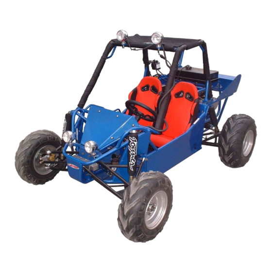
OWNER’S MANUAL FOREWORD Thank you for choosing JOYNER Go-Kart. We hope you will have fun with it. Before you start operate the Go-Kart, please read through this Owner’s Manual carefully as it contains important safety and maintenance information. Failure to follow the warnings contained in this manual can result in serious injuries. -
Page 6: A Few Words About Safety
A FEW WORDS ABOUT SAFETY In order to keep everyone safe, you must take responsibility for the safe operation of your Go-Kart. To help you make informed decisions about safety, we have provided operating procedures and other information on labels and in this manual. This information alerts you to potential hazards that could hurt you or others. -
Page 7: Important Safety Information
IMPORTANT SAFETY INFORMATION Your Go-Kart will provide you with many years of service and pleasure. Providing you take responsibility for your own safety and understand the challenges you can meet while driving. There is much that you can do to protect yourself when you drive. You’ll find many helpful recommendations throughout this manual. - Page 8 IMPORTANT SAFETY INFORMATION Never run your Go- Kart indoors. The exhaust from the engine contains a tasteless, odorless and poisonous gas called carbon monoxide. Keep away from moving parts of the Go-Kart The operator of the Go-Kart should never place their hands or other parts of their body near any moving part of the Go-Kart.
-
Page 9: Safety Labels
SAFETY LABELS This section presents some most important information recommendations to help you drive your Go-Kart safely, Please take a few moments to read these pages. The labels be considered permanent parts of the Go-Kart. If a label comes off or becomes hard to read, contact your dealer for warning labels replacements. -
Page 10: Are You Ready To Drive
ARE YOU READY TO DRIVE? Before each drive, you need to make sure you and your Go-Kart are both ready to drive. To help get you prepared, this section discusses how to evaluate your driving readiness, what items you should check on your Go-Kart, and adjustments to make for your comfort, convenience, or safety. - Page 11 ARE YOU READY TO DRIVE? Drive Training Developing your driving skills is an on-going process. Even if you have driven other Go-Karts, take time to become familiar with how this Go-Kart works and handles. Practice driving the Go-Kart in a safe area to build your skills. Do not drive in rough terrain until you get accustomed to the Go-Kart’s controls, and feel comfortable with its size and weight.
-
Page 12: Is Your Vehicle Ready To Drive
IS YOUR VEHICLE READY TO DRIVE? Before each drive, it is important to inspect your Go-Kart and make sure any problems you find are corrected. A pre-drive inspection is a must, not only for safety, but because having a breakdown, or even a flat tire, can be a major inconvenience. If your Go-Kart has overturned or has been involved in a collision, do not drive it until your Go-Kart has been inspected by your dealer, There may be damages or other problems you can not see. - Page 13 IS YOUR VEHICLE READY TO DRIVE? Lights ■ Make sure the headlight, brake light and tail light are working properly. Throttle ■ Check the free play and adjust if needed. Press the throttle to make sure it moves smoothly without sticking, and snaps back automatically when it is released. Clutch cable ■...
-
Page 14: Safe Driving Precautions
SAFE DRIVING PRECAUTIONS Off-Road Use Only Your Go-Kart and its tires are designed and manufactured for off-road use only, not for pavement. Driving on pavement can affect handling and control. You should not drive your Go-Kart on pavement. Operating this Go-Kart on paved surfaces may seriously affect handling and control of the Go-Kart, and may cause the vehicle to go out of control. -
Page 15: Safe Driving Precautions
SAFE DRIVING PRECAUTIONS Control Speed Driving at excessive speed increases the chance of an accident. In choosing a proper speed, you need to consider the capability of your Go-Kart, the terrain, visibility and other operating conditions, plus your own skills and experience. Operating this Go-Kart at excessive speeds increases your changes of losing control of the Go-Kart, which can result in an accident. -
Page 16: Specifications
SPECIFICATIONS DIMENSIONS Overall Length---------------------------------------------------------------------------------------88.6 in. (2250mm) Overall Width --------------------------------------------------------------------------------------- 55.5in. (1410mm) Overall Height ---------------------------------------------------------------------------------------- 57.5 in. (1460mm) Wheelbase --------------------------------------------------------------------------------------------- 62.4 in. (1585mm) Front Track ------------------------------------------------------------------------------------------- 47.5 in. (1208mm) Rear Track -------------------------------------------------------------------------------------------47.6 in. (1210mm) Ground Clearance ------------------------------------------------------------------------------------ 10.5 in. (265mm) ENGINE Type --------------------------------------------------------------------------- 1-Bore,4-Stroke, forcedly air-cooled Bore x Stroke ---------------------------------------------------------------------------------------- 57.4mm×57.8mm Displacement ----------------------------------------------------------------------------------------------------- 149.5cc... -
Page 17: Operation
OPERATION A. Operation controls WARNING-Do not attempts to start or operate the engine until completely familiar with the location and use of each control necessary to operate this vehicle. The operator must know how to stop this machine before starting and driving it. a. - Page 18 OPERATION e. Pre-Drive Inspection Perform this pre-drive inspection everyday before driving vehicle. If not performed, serious damage to the vehicle or personal injury may result. 1. Check for Engine Oil Level. Check for transmission Oil Level. Check for leaks, add oil if required.
-
Page 19: Operation
OPERATION Pull seat adjustment handle upward to disengage seat slide. b. Move seat to desired position. Be sure seat adjustment handle snaps back into place and that seat is locked into position. (See Fig. 3 ) Before attempting to adjust the seat ensure that engine of the Go-Kart is stopped. Never operate this Go-Kart when the provided seat is not securely fastened, to do so could result in a strong possibility of severe personal injury or loss of life. -
Page 20: Service Instructions
SERVICE INSTRUCTIONS A. Service Air Cleaner Service air cleaner every 80 hours NOTE: Service more often under dusty conditions. Remove cleaner cover (See Fig. 6) Figure 5 Figure 6 b. Remove air cleaner filter (See Fig. 8) Figure 7 Figure 8 Check the air cleaner filter, if the filter is dusty, please replace with a new one. - Page 21 SERVICE INSTRUCTIONS Figure 9 Figure 10 Figure 11 a. Put the vehicle on the level ground. b. Shut down the engine, put a collecting oil plate under the engine oil outlet. Loosen the oil outlet plug in the warm engine. Let the engine oil out fully (see Fig. 9). c.
- Page 22 SERVICE INSTRUCTIONS D. Carburetor Adjustment Never make unnecessary adjustments. The factory recommended settings are correct for most applications. It’s not necessary to disassemble the screw unless the carburetor needs to be replaced. Prepare a 50r/w tachometer before adjustment. a. Warm up the engine (5~10min) b.
-
Page 23: Repair
REPAIR A. Front Wheel Replacement Do not disassemble the castle nuts when you replace the front wheels. It is only necessary to tighten the nuts so that the wheel turns freely on the axle with minimum end play. (See Fig. 14) Tighten the nuts after replacing the wheels. Figure 14 B. -
Page 24: Periodical Check And Services
PERIODICAL CHECK AND SERVICES The maintenance intervals in the following table are based upon average driving conditions. Driving in unusually dusty areas, require more frequent servicing. Time of service Initial Monthly Quarterly Yearly service Item Engine 1. Fan, driven belt 2. - Page 25 WIRING DIAGRAM...
-
Page 26: Parts Manual
PARTS MANUAL 1 CYLINDER HEAD ASSY. - Page 27 1 CYLINDER HEAD ASSY.
-
Page 28: Cylinder Assy
2 CYLINDER ASSY... -
Page 29: Crankcase Assy.(1)
3 CRANKCASE ASSY.(1) -
Page 30: Crankcase Assy(2)
4 CRANKCASE ASSY.(2) - Page 31 4 CRANKCASE ASSY.(2)
-
Page 32: Crankshaft Con'rod&Piston Assy
5 CRANKSHAFT CON'ROD&PISTON ASSY... -
Page 33: Camshaft Assy
6 CAMSHAFT ASSY. -
Page 34: Left Cover Assy
7 LEFT COVER ASSY. -
Page 35: Fan Cover And Shroud Assy
8 FAN COVER AND SHROUD ASSY. -
Page 36: Oil Pump Assy
9 OIL PUMP ASSY. -
Page 37: Driven Pulley And Clutch Subassy
10 DRIVEN PULLEY AND CLUTCH SUBASSY. -
Page 38: Transmission Assy
11 TRANSMISSION ASSY. -
Page 39: Electric System
12 ELECTRIC SYSTEM... -
Page 40: Electric Starter Assy
13 ELECTRIC STARTER ASSY. -
Page 41: Drive Pulley Subassy
14 DRIVE PULLEY SUBASSY. -
Page 42: Gomp.of Gy Rever Se Gear Engine
15 GOMP.OF GY REVER SE GEAR ENGINE... - Page 43 15 GOMP.OF GY REVER SE GEAR ENGINE...
-
Page 44: Carburetor
16 CARBURETOR... - Page 45 16 CARBURETOR...
-
Page 46: Frame
17 FRAME 3 4 5... - Page 47 17 FRAME Q'TY PART NO. DESCRIPTION HP-30 RUBBER CHOCK PLUG DS150.01.01.00.00 MAIN FRAME GB/T818-2000 M6X16 CROSS PANHEAD SCREW M6X16 JD0900008 RUBBER GASKET 6 GB/T6187-2000 M6 SELF-LOCKING FLANGE NUT M6 BOARD BEHIND THE SEAT DS150.01.01.02.30 HEAT-PROTECTING ALUMINIUM FOIL DS150.11.01.00.01 RUBBER COVER.SHIFT DS150.11.16.00.00 D250.01.000-210A NETHER BOARD OF ELECTRICAL INSTALLATION...
-
Page 48: Protective Bar
18 PROTECTIVE BAR Q'TY PART NO. DESCRIPTION DS150.01.02.01.00 LEFT PROTECTIVE BAR GB/T70.1-2000 M10X30 INNER HEXAGON BOLT M10X30 GB5787-86 M12X1.25X60 FLANGE BOLT M12X1.25X60 D250.11.771 NYLON BUSH GB6177.1-2000 M12 FLANGE NUT M12 GB/T6187-2000 M6 SELF-LOCKING FLANGE NUT M6 D650.04.06.00.02 LIMITED PLATE OF CARBON FILTER GB5787-86 M6X20 FLANGE BOLT M6X20 D650.04.06.00.01... - Page 49 18 PROTECTIVE BAR Q'TY PART NO. DESCRIPTION GB6177.1-2000 M10 FLANGE NUT M10 DS150.01.02.03.00 FRONT PROTECTIVE BAR DS150.01.02.02.00 RIGHT PROTECTIVE BAR DS150.01.02.02.00 OPTIONAL ALUMINUM ROOF RACK GB/T6177-2000 M10X1.25 FLANGE NUT M10X1.25 D1600.01.02.00.07 RACK SPACER SLEEVE D1600.08.01.00.06 LOOP M10X1.25...
-
Page 50: Front Suspension
19 FRONT SUSPENSION 35 36... - Page 51 19 FRONT SUSPENSION Q'TY PART NO. DESCRIPTION DS250.02.00.00.02 STUB AXLE.R DN250.04.01.00.02 BRAKE CALIPER 2 DS250.02.00.00.05 UNIVERSAL JOINT.L DS150.02.03.00.00 SUSPENSION ARM.LOWER.FL DS150.02.02.00.00 SUSPENSION ARM.UPPER.FL GB6177.1-2000 M12X1.5 FLANGE NUT M12X1.5 POSA12 ROD END BEARING 12 D800.05.01.00.03 SPACER SLEEVE. 12 GB5787-1986 M12X1.5X65 FLANGE BOLT M12X1.5X65 GB6173-1986 M12X1.5 THIN NUT M12X1.5 DS150.02.05.00.00...
- Page 52 19 FRONT SUSPENSION Q'TY PART NO. DESCRIPTION DN250.04.01.00.04 FRACTION PLATE 2 DN250.04.01.00.03 FRACTION PLATE 1 DN250.04.01.00.06 SPRING PLATE 2.BRAKE CLIPPER...
-
Page 53: Control System Assembly
20 CONTROL SYSTEM ASSEMBLY 63 62... - Page 54 20 CONTROL SYSTEM ASSEMBLY Q'TY PART NO. DESCRIPTION GB/T91-2000 3.2X40 COTTER PIN 3.2X40 GB/T6179-1986 M10 SLOTTED NUT M10 SPRING WASHER 10 GB/T93-1987 10 GB/T95-1985 10 PLAIN WASHER 10 DS250.03.00.00.02 TIE ROD END GB6172.1-2000 M12X1.25 THIN NUT M12X1.25 DS150.03.03.00.00 TIE ROD GB6172.1-2000 M12LX1.5 THIN NUT M12LX1.5 GB5787-1986 M12X1.25X80...
- Page 55 20 CONTROL SYSTEM ASSEMBLY 63 62...
- Page 56 20 CONTROL SYSTEM ASSEMBLY Q'TY PART NO. DESCRIPTION GB818-85 M4×5 CROSS PANHEAD SCREW M4x5 GB/T93-1987 4 SPRING WASHER 4 DN250.04.01.01.00 MAIN PISTON.BRAKE GB6187.1-2000 M8 FLANGE LOCK NUT M8 DN250.04.01.00.07 PUSH POLE.BRAKE GB6172.1-2000 M8 THIN NUT M8 GB/T91-2000 3X30 COTTER PIN 3X30 FLANGE BOLT M8X30 GB5787-1986 M8X30 D250.10.005...
-
Page 57: Rear Suspension
21 REAR SUSPENSION... - Page 58 21 REAR SUSPENSION Q'TY PART NO. DESCRIPTION DN250.04.01.00.02 BRAKE CALIPER 2 GB/T93-1987 8 SPRING WASHER 8 GB6177.1-2000 M8X15 FLANGE NUT M8X15 DS150.09.03.00.00 REAR ARM.R GB6177.1-2000 M10X1.25 FLANGE NUT M10X1.25 D650.02.01.00.01 RUBBER BUSHING.REAR ARM D650.02.01.00.02 STEEL BUSHING.REAR ARM FLANGE BOLT M10X1.25X80 GB5787-1986 M10X1.25X80 DI250.07.01.00.01 BRIDLE.BOOT...
-
Page 59: Mid Axis Assembly
22 MID AXIS ASSEMBLY Q'TY PART NO. DESCRIPTION DI250.07.00.00.01 SPRING CIRCLIP GB894.1-86 26 CIRCLIP FOR AXIS 26 GREASE SEAL FB 38X62X8 GB/T9877-1988 FB38X62X8 GB77-85 M5X6 HOLDING SCREW M5X6 DN250.07.00.00.03 SLEEVE.SPROCKET SHAFT GB5787-1986 M12X1.5X45 FLANGE BOLT M12X1.5X45 GB893.1-86 62 CIRCLIP FOR HOLE 62 GB/T281-1994 1206 TWO-ROW BALL BEARING DN250.07.00.00.06... -
Page 60: Engine System Assembly
23 ENGINE SYSTEM ASSEMBLY Q'TY PART NO. DESCRIPTION FLANGE BOLT M10X1.25X180 GB5787-1986 M10X1.25X180 JD11000013 HANGING GB6177.1-2000 M10X1.25 FLANGE NUT M10X1.25 FLANGE BOLT M10X1.25X55 GB5787-1986 M10X1.25X55 ENGINE FIXED MOUNT DS150.01.03.00.00 ENGINE ASSEMBLY DS150.07.03.00.00 CAPPED NUT.EXHAUST PIPE DS150.05.03.00.02 EXHAUST ELBOW PIPE DS150.05.03.00.01 INTAKE CLAMP OF MUFFLER DI250.05.02.00.02 EXHAUST PIPE... - Page 61 23 ENGINE SYSTEM ASSEMBLY Q'TY PART NO. DESCRIPTION DS150.05.03.00.05 SLEEVE.EXHAUST PIPE FLANGE BOLT M8X50 GB5787-1986 M8X50 FLANGE BOLT M8X20 GB5787-1986 M8X20 GB/T6187-2000 M6 SELF-LOCKING FLANGE NUT M6 GB5787-86 M6X20 FLANGE BOLT M6X20 DS150.01.04.00.02 FIXED BAR OF AIR FILTER DS150.05.02.01.00 AIR FILTER AIR CLEANER FILTER DS150.05.02.01.01 HOSE CLAMP...
- Page 62 23 ENGINE SYSTEM ASSEMBLY Q'TY PART NO. DESCRIPTION FULL-THREAD BOLT M12X1.75X100 GB5783-2000 M12X1.75X100 NUT M12X1.75 GB6170-2000 M12X1.75 MOUNTING.CARBURETOR DS150.05.02.02.01 CARBURETOR DS150.05.02.02.00 MOUNTING.AIR FILTER DS150.05.02.01.01 GB5787-86 M10X1.25X70 FLANGE BOLT M10X1.25X70...
-
Page 63: Fuel Tank
24 FUEL TANK Q'TY PART NO. DESCRIPTION GB6177.1-2000 M10 FLANGE NUT M10 DS250.08.00.00.03 ENGINE BUMPER DS150.01.03.00.00 FIXED BAR OF ENGINE GB/T6187-2000 M6 SELF-LOCKING FLANGE NUT M6 DS150.01.04.00.02 FIXED BAR OF AIR FILTER GB5787-86 M6X20 FLANGE BOLT M6X20 GB/T6187-2000 M8 SELF-LOCKING FLANGE NUT M8 JD1910003 RUBBER BUSH.WATER TANK JD1910002... -
Page 64: Electrical Appliance
25 ELECTRICAL APPLIANCE Q'TY PART NO. DESCRIPTION DS150.10.06.00.00 SPOT LIGHTS DS150.10.03.00.00 HEADLIGHT D250.07.915 VOLTAGE REGULATOR DI250.10.05.00.00 IGNITION COIL DS150.10.04.00.00 D250.07.912 RELAY DS150.10.01.01.00 FUSE BOX DS150.10.08.00.00 HORN D250.07.802 BATTERY D650.08.05.00.06 PLASTIC TAP DS150.10.09.00.00 TAILLIGHT DS150.10.01.00.00 ELECTRIC CABLE JD0830000 IGNITION SWITCH D650.06.00.13.00 HORN BUTTON DS150.10.02.00.00 PANEL SWITCH... -
Page 65: Other Parts
26 OTHER PARTS Q'TY PART NO. DESCRIPTION SAFETY BELT DS150.11.02.00.00 SEAT DS150.11.01.00.00 GB/T6187-2000 M8 SELF-LOCKING FLANGE NUT M8 COWL DS150.11.08.00.00 CEILING DS150.11.07.00.00 2 pairs COWL.SHOCK ABSORBER DS150.11.10.00.00 COWL.PROTECTIVE BAR 1 series DS150.11.03.00.00 FOAM COVER DS150.11.14.00.00 1 series... -
Page 66: Preparation Attach Instruction
PREPARATION ATTACH INSTRUCTION ATTACH BATTERY STEP 1:FILL THE ELECTROLYTE AS BELOW a) Pull the seal cap out of the plastic bottle b) Turn over the seal cap 180 degree, fix it on the outlet of plastic bottle c) Cut the inlet of plastic bottle d) Fill the battery with electrolyte to upper lever by inserting every inlet of the battery STEP 2:Put the battery into the box on go-kart. -
Page 67: Attach Protective Bars
ATTACH PROTECTIVE BARS 1、 2、 ATTACH REAR SHOCK a) Remove the bolt and the nut b) Attach the rear shock as below pictures:... -
Page 68: Attach Trailing Arm
ATTACH TRAILING ARM 1、 2、 ATTACH BRAKE PIPE Front: Rear:... -
Page 69: Attach Front Shock
ATTACH FRONT SHOCK 1- Remove pin, nut, adjust cushion from the bolt on the tie rod. 2- Insert the tie rod into the hole on the front wheel axle. 3- Tighten the nut, insert the pin, then lock the pin. 4- Put the upper hole of the front shock into the groove on the frame. -
Page 70: Attach Front Tire
ATTACH FRONT TIRE The hub to fix the front tire is packed as below: 1- Remove four nuts, four spring washers, four plain washers on the hub. 2- Fix the rim on the hub. 3- Insert the washers, spring washers through bolt on the hub. Tighten four nuts. Notice: Direction marked on the tire must correspond to the vehicle forward... -
Page 71: Dealer Pre-Delivery Inspection
DEALER PRE-DELIVERY INSPECTION... - Page 72 ____Jumping the vehicle can cause serious damage to the drive train (axle, transmission, suspension). _______Injury or death can result from jumping vehicle. Do Not Jump. _______I understand that the roll bars are cosmetic and a roll over could cause death or serious injury.
- Page 73 returned check charge plus any actual charges assessed by Seller’s financial institution resulting from such returned check. 5. ATTORNEYS FEES. If it is necessary for Seller to take legal action to enforce any of seller’s rights under this contract, Buyer agrees to pay to the extent permitted by law, the seller‘s reasonable attorneys fees and court costs.
- Page 74 reason, Seller may at Seller’s sole option, terminate this contract and retake the vehicle, or make claims against Buyer on the check. In addition, Seller will charge Buyer a $25 returned check charge plus any actual charges assessed by Seller’s financial institution resulting from such returned check.