Table of Contents
Advertisement
Quick Links
Owner's Manual
Repair Manual
Parts manual
READ THIS MANUAL CAREFULLY
IT CONTAINS IMPORTANT SAFETY INFORMATION.
MINIMUM
RECOMMENDED
OPERATOR AGE:
16
FOR OFF-ROAD USE ONLY
This vehicle is designed and manufactured for off-road use only.
It does not confirm to federal motor vehicle safety standards, and operation on
public streets, roads, or highways is illegal.
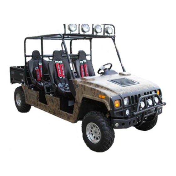
Renegade
R2,R4
Advertisement
Table of Contents

Related Manuals for Joyner Renegade R2


Summary of Contents for Joyner Renegade R2
-
Page 1: Parts Manual
Owner’s Manual Renegade Repair Manual R2,R4 Parts manual READ THIS MANUAL CAREFULLY IT CONTAINS IMPORTANT SAFETY INFORMATION. MINIMUM RECOMMENDED OPERATOR AGE: FOR OFF-ROAD USE ONLY This vehicle is designed and manufactured for off-road use only. It does not confirm to federal motor vehicle safety standards, and operation on public streets, roads, or highways is illegal. - Page 2 Thank you for choosing JOYNER JNSZ800UV. It represents the result of many years of JOYNER experience in the production of utility vehicles. With the purchase of this JOYNER, you can now appreciate the high degree of craftsmanship and reliability that have made JOYNER a leader in this field.
-
Page 3: Table Of Contents
OWNER’S MANUAL............................8 1 WARRANTY POLICY .......................... 8 Liability Release of Joyner Recreational Vehicle ................9 Team Joyner USA Limited Manufacturer’s Defect Warranty ............. 10 Parts Order Form and Warranty Claim Form ................12 Service Record Form........................13 Preventative Maintenance and Service Log ................14 2 LOCATION OF THE WARNING AND SPECIFICATION LABELS .......... - Page 4 Starting and operating instructions ....................39 7 MAINTENANCE AND ADJUSTMENT .................... 40 Air cleaner ............................40 Engine Lubrication ........................... 40 Transmission lubrication ......................... 41 Differential lubrication ........................41 Engine coolant ..........................42 Idle Speed ............................43 Spark plug inspection ........................43 Wedge belt figure ..........................
- Page 5 1.2 Cylinder block .......................... 147 1.3 Crankshaft ..........................148 1.4 Exhaust manifold ........................149 1.5 Intake system ........................... 150 1.6 Lubricating device ........................151 1.7 Cylinder head ........................... 152 1.8 Cover-valve chamber ......................153 1.9 Oil pan ............................154 1.10 Valve mechanism ........................155 1.11 Ignition device ........................
- Page 6 3.16 Pedal and parking brake of R2.................... 195 3.17 Hydraulic pump assembly of foot brake of R2 ..............197 3.18 Hydraulic pump assembly of parking brake of R2 and R4 ..........198 3.19 Clutch hydraulic assembly of R2 ..................199 3.20 Pedal and parking brake of R4....................
- Page 7 4.10 New front metal bumper kit of R2 and R4 ................. 248 4.11 Canvas windshield kit of R2 and R4 ................... 249 4.12 Simple windshield kit of R2 and R4 ..................250 4.13 Safari bed kit of R2 and R4 ....................251 4.14 Enclosure with plastic door kit of R2 ..................
-
Page 8: Owner's Manual
OWNER’S MANUAL 1 WARRANTY POLICY 8 / 278... -
Page 9: Liability Release Of Joyner Recreational Vehicle
Liability Release of Joyner Recreational Vehicle 9 / 278... -
Page 10: Team Joyner Usa Limited Manufacturer's Defect Warranty
Team Joyner USA Limited Manufacturer’s Defect Warranty 10 / 278... - Page 11 11 / 278...
-
Page 12: Parts Order Form And Warranty Claim Form
Parts Order Form and Warranty Claim Form 12 / 278... -
Page 13: Service Record Form
Service Record Form 13 / 278... -
Page 14: Preventative Maintenance And Service Log
Preventative Maintenance and Service Log 14 / 278... - Page 15 15 / 278...
- Page 16 16 / 278...
- Page 17 17 / 278...
- Page 18 18 / 278...
-
Page 19: Location Of The Warning And Specification Labels
Read and understand all of the labels on your vehicle. They contain important information for safe and proper operation of your vehicle. Never change any labels’ position and remove them from your vehicle. If a label becomes difficult to read or comes off, a replacement label is available from your Joyner dealer. 19 / 278... - Page 20 See the next form (Pic 1.15) and it will tell you the JOYNER’s parts No. and the quantity of each label for your Renegade R2 or R4. 20 / 278...
-
Page 21: Safety Information
3 SAFETY INFORMATION THE SAFETY IS FRIST. Severe injury or death can result if you do not follow these instructions. Read this manual and all labels carefully and follow the operating procedures described: 1. This vehicle is designed to carry the driver and one passenger. Never carry passengers in the cargo bed. - Page 22 17. Never operate the vehicle on hills that are too steep for it or for your abilities. Go straight up and down hills where possible. Maximum slope angle: 11º . 18. Never operate on hills that are slippery or ones where you will not be able to see far enough ahead of you.
-
Page 23: Are You Ready To Drive
4 ARE YOU READY TO DRIVE? Before each drive, you need to make sure you and your Renegade are both ready to drive. To help get you prepared, this section discusses how to evaluate your driving readiness, what items you should check on your Renegade, and adjustments to make for your comfort, convenience, and safety. -
Page 24: Drive Training
Drive training Developing your driving skills is an on-going process. Even if you have driven other Renegade, take time to become familiar with how Renegade works and handles. Practice driving Renegade in a safe area to build your skills. Do not drive in rough terrain until you get accustomed to Renegade’s controls, and feel comfortable with its size and weight. -
Page 25: Is Your Vehicle Ready To Drive
5 IS YOUR VEHICLE READY TO DRIVE? Before each drive, it is important to inspect your Renegade and make sure any problems you find are corrected. A pre-drive inspection is a must, not only for safety, but because having a breakdown, or even a flat tire, can be a major inconvenience. - Page 26 ■ Leaks, Loose Parts Walk around your Renegade and look for anything that appears unusual, such as a leak or loose cable. ■ Light Make sure the headlight, brake light, turning light and tail light are working properly. ■ Throttle pedal Check the free play of throttle pedal and adjust if needed.
-
Page 27: Operation Instruction
3. If some exigency happens about the circuits, shut down the switch first. 4. If lose the key, please connect your local JOYNER dealer. It is important to your renegade and yourself safety for the main electrical kill switch to control the overall power, so keep it clean all the time. -
Page 28: Gauges
START: The electric starter is engaged by turning and holding the key in this position. Release the key when the engine starts. Do not operate the electric starter continuously for more than 5 seconds, or starter damage could occur. Wait at least 5 seconds between each operation of the electric starter to let it cool. Do not turn the key to the "START"... -
Page 29: Control Switches
JOYNER dealer and change a new one. Before riding out, please check them work well. Control switches Light switches Set the switch to to turn on the low beam and the taillights. -
Page 30: Indicator Lights
NOTE: To the new dash, there is a three blank switch assembly. It is prepared for you to upgrade your Renegade with JOYNER’s opinions: Heater, rain wiper, Electric hydraulic lifter of cargo bed and so on. Is you have interest about the opinions, please connect your local JOYNER dealer. -
Page 31: Differential-Locker Holder
Renegade. SAFETY IS FIRST, before engage the locker, please read the label (label code:JOYNER-099, see Pic 2.9) which is stuck near by the handle carefully. There is a big difference about the differential-locker holder between the old and the new dash. The next Pic 6.10 shows the old locker holder and the Pic 6.11 shows the new one. -
Page 32: Brake Pedal
Loosen the flange nut M10x1.25 on the accelerator cable to make the cable can move freely. Loosen the two flange nut M6 and the hex bolts M6x45, M6x60. Adjust the hex bolts to change the dimension L (see Pic 6.12) and press the pedal with you right foot until you feel very comfortable and smoothly. -
Page 33: Parking Brake Lever
If you cannot do it yourself, please connect your local JOYNER dealer. Although the master cylinder can push the pedal return its original position when released, the release spring is also necessary and never remove it off. -
Page 34: Gear Shift Lever
Adjust the parking cable if necessary. Be sure to fully release the parking brake lever before driving the vehicle. It is allowed use the parking lever as an emergency brake if the foot brake can’t work. Gear shift lever Before operate the vehicle, check the shift lever as to change gearshift from 1 to 5 and reverse smoothly. -
Page 35: Fuel Tank
The speed of vehicle The first 1000 km Gear 20km/h(12.5mile/h) Gear 35km/h(21.9mile/h) Max speed in each gear Gear 54km/h(33.8mile/h) Gear 73.3km/h(45.8 mile/h) Gear 90km/h(56.3 mile/h) Fuel tank The fuel tank is located under the driver’s seat (see Pic 6.20). Remove the fuel tank cap by turning counterclockwise when fill gasoline. -
Page 36: Seat Belts
upward, hold the lever in that position and adjust the seat to the desired position. Be sure the adjustment lever is back on its full lock position and the seat is locked in place. Pull seat lock lever under left leg upward. Move the Seats backwards or forwards as your need. -
Page 37: Kartgo Bed
Push the latch plates into the buckle, use a hook connects the end of the belt which crosses left leg and set level. Pull up on the latch plates to make sure it is secure see Pic 6.28- Pic 6.29. Cross the shoulder belt over your shoulder and the leg belt over your leg. -
Page 38: Start Engine
Start engine Engage the parking brake if necessary. Pressing down the clutch pedal can make starting easier, so do that if necessary. 3 Make sure the shift lever in neutral position. 4 Turn the key clockwise to the “start” position and hold it for less than 5 seconds, if engine not started. -
Page 39: Starting And Operating Instructions
2. Drive vehicle from stop to low speed slowly. 3. Avoid braking strongly. 4. Do not exceed the vehicle speed on the below schedule. The speed of vehicle The first 1000 km Gear 20km/h(12.5mile/h) Gear 35km/h(21.9mile/h) Max speed in each gear Gear 54km/h(33.8mile/h) Gear... -
Page 40: Maintenance And Adjustment
7 MAINTENANCE AND ADJUSTMENT Air cleaner It is stander high street air cleaner of your Renegade. Under dusty conditions Service more often. Remove filter cover; check the filter cover and the air filter, if dusty, blow off dust with clear and dry air. If necessary, replace with a new one. -
Page 41: Transmission Lubrication
Transmission lubrication Oil replacement It must change the oil in the transmission after the first 5 hours of operating of your new engine and after 10 hours of use thereafter. That will insure proper lubrication of internal parts and prevent costly repairs due to excessive wear. -
Page 42: Engine Coolant
Tighten the differential oil outlet bolt. Remove the oil inlet bolt; fill oil (API 80(75) W-90 GL-3 Gear Oil) about 0.4 liters. Replace the oil inlet bolt, and tighten with 30Nxm torque. The inlet bolt has magnetism to adsorb scrap iron in the oil, so never use a bolt without magnetism to replace it. -
Page 43: Idle Speed
Idle Speed The engine is EFI (electric fuel injection), and the idle speed has been adjusted well and controlled by ECU, so never change the idle speed. It is very necessary to adjust the accelerator pedal to make sure there is some free travel of the accelerator cable. -
Page 44: Wedge Belt Figure
Wedge belt figure Correct installation and the proper tension will ensure electrical generator and air conditioner work well. If chap, tear, wear,or looseness happen, contact Joyner dealer and replace it immediately. Check the belt tension: Apply a pressure (about 100N/22.48lbf) on the belt, if the movement is more than 10mm/0.4inch, loosen the flange bolt and change the position of starter to tension the belt and fasten the bolt. -
Page 45: Shift Cable Adjustment
Shift cable adjustment After a long time use, more and more free play of shift cable make gear position is not accurately or shift lever in a wrong position, so adjust the shift cable refer to Preventative maintenance and service log. Loosen the adjustment nuts, move the cable forwards or backwards according situation, repeat it until find a position where gear shift work correctly and the shift lever work in a proper position. -
Page 46: Differential Lock Cable Adjustment
Loosen the flange nut M10x1.25 and the thin nut M8 to make the cable and the parking arm can move freely. Adjust the master rod to make sure the distance between rod holder and the master cylinder L=18mm (0.71in)-22(0.87in), then fasten the nut. Adjust the round nut M8 and the flange nut M10x1.25 to make sure there is a 10mm (0.4in) free travel for the parking lever, and fasten the nut. -
Page 47: Spot Light Adjustment
Spot light adjustment To get the desired spot-light position, adjust as following steps: Solution 1: No adjustment to sport light bar and only adjust the sport light Loosen the sport light adjustment nut, and turn sport light forwards and backwards until find the desired position. -
Page 48: Fuel Pressure Adjuster Adjustment
Just take off these 4 hub nuts, and replace the wheels with a new one. Tighten these 4 hub nuts after replacing the wheels, the wheel need to be assembled by a JOYNER authorized dealer, see Pic 7.22. -
Page 49: Rear Wheel Replacement
It is not needed to disassemble the center castle nuts when you replace the front wheels or the rear wheels. Just take off these 5 cap-nuts, and replace the wheels with a new one. Tighten these 5 nuts after replacing the wheels, the wheel need to be assembled by a JOYNER authorized dealer, see Pic 7.23. -
Page 50: Front Wheel Alignment
plate, see Pic 7.32-Pic 7.34. Caution: When fix the six bolts in the Clutch pressure plate; You must tighten them according to the prescribed torque 20.5 Ft_Lb. Replace a new clutch, and then insert a spline-shaft into the hole of the Clutch assy, fix the six bolts on the Clutch pressure plate, and tighten them according to the prescribed torque 20.5 Ft_Lb, see Pic 7.35-Pic 7.36. -
Page 51: Fuses And Relays
Put the vehicle on level ground. The “toe-in” of the front wheels should be 10mm~20mm(0.4in~0.79in). It means the dimension A should be more 0.4i~0.79 inches than dimension B. Turn the steering wheel to put the steer shaft in the center position, see Pic 7.37. Loose the adjustment nuts on both ends of Front Tie Rods. -
Page 52: Bulb Replacement
Bulb replacement To replace the bulb of the sport light, do the following, see Pic 7.41-Pic 7.46: Loose the 2 crews at the bottom of the head light, and take off the 2 hoops around the head light. Separate the head light as the picture. Unscrew the screw that fixes the bulb, and take off the bulb carefully. -
Page 53: Shock Adjustment
Separate the taillight cover from the taillight body. Take off the bulb you need to replace through turning the bulb counter clockwise about a half round, and replace a new one. Put all the parts back with reversing step 1~2. Shock adjustment The front and rear shocks cannot be adjusted. -
Page 54: Principle Diagram Of Wiring
Principle diagram of wiring 54 / 278... -
Page 55: No.1 Harness Wiring Diagram Of R2 And R4 (Old)
No.1 harness wiring diagram of R2 and R4 (old) 55 / 278... -
Page 56: No.2 Harness Wiring Diagram Of R2 And R4 (Old)
No.2 harness wiring diagram of R2 and R4 (old) 56 / 278... -
Page 57: No.1 Harness Wiring Diagram Of R2 And R4 (New)
No.1 harness wiring diagram of R2 and R4 (new) 57 / 278... -
Page 58: No.2 Harness Wiring Diagram Of R2 And R4 (New)
No.2 harness wiring diagram of R2 and R4 (new) 58 / 278... -
Page 59: Specifications
Intake duct Dry element Fuel: Type Unleaded gasoline only Fuel tank capacity Fuel system: Type Spark plug: Type/manufacturer S11-3707100/ JOYNER Clutch type: Dry, diaphragm spring Transmission: Transmission type Manual Operation Right hand operation (five shifts, one reverse) 59 / 278... - Page 60 Chassis Frame type Steel tube frame Caster angle 3º Tire Type Tubeless Size front 27 inch rear 27 inch Brakes: System Front and rear unified Type front Dual disc brake rear Dual disc brake Operation Foot operation Suspension: Front suspension Independent Dual A-Arm Rear suspension Longitudinal Control Arm...
-
Page 61: Repair Manual
REPAIR MANUAL 1 ENGINE MECHANICAL SYSTEMS 61 / 278... - Page 62 62 / 278...
- Page 63 63 / 278...
- Page 64 64 / 278...
- Page 65 65 / 278...
- Page 66 66 / 278...
- Page 67 67 / 278...
- Page 68 68 / 278...
- Page 69 69 / 278...
- Page 70 70 / 278...
- Page 71 71 / 278...
- Page 72 72 / 278...
- Page 73 73 / 278...
- Page 74 74 / 278...
- Page 75 75 / 278...
- Page 76 76 / 278...
- Page 77 77 / 278...
- Page 78 78 / 278...
- Page 79 79 / 278...
- Page 80 80 / 278...
- Page 81 81 / 278...
- Page 82 82 / 278...
- Page 83 83 / 278...
- Page 84 84 / 278...
- Page 85 85 / 278...
- Page 86 86 / 278...
- Page 87 87 / 278...
- Page 88 88 / 278...
- Page 89 89 / 278...
- Page 90 90 / 278...
- Page 91 91 / 278...
- Page 92 92 / 278...
- Page 93 93 / 278...
- Page 94 94 / 278...
- Page 95 95 / 278...
- Page 96 96 / 278...
- Page 97 97 / 278...
- Page 98 98 / 278...
- Page 99 99 / 278...
- Page 100 100 / 278...
- Page 101 101 / 278...
- Page 102 102 / 278...
- Page 103 103 / 278...
- Page 104 104 / 278...
-
Page 105: Electric Injection System
2 ELECTRIC INJECTION SYSTEM 105 / 278... - Page 106 106 / 278...
- Page 107 107 / 278...
- Page 108 108 / 278...
- Page 109 109 / 278...
- Page 110 110 / 278...
- Page 111 111 / 278...
- Page 112 112 / 278...
- Page 113 113 / 278...
- Page 114 114 / 278...
- Page 115 115 / 278...
- Page 116 116 / 278...
- Page 117 117 / 278...
- Page 118 118 / 278...
- Page 119 119 / 278...
- Page 120 120 / 278...
- Page 121 121 / 278...
- Page 122 122 / 278...
- Page 123 123 / 278...
- Page 124 124 / 278...
- Page 125 125 / 278...
- Page 126 126 / 278...
- Page 127 127 / 278...
- Page 128 128 / 278...
- Page 129 129 / 278...
- Page 130 130 / 278...
- Page 131 131 / 278...
- Page 132 132 / 278...
- Page 133 133 / 278...
- Page 134 134 / 278...
- Page 135 135 / 278...
- Page 136 136 / 278...
- Page 137 137 / 278...
- Page 138 138 / 278...
- Page 139 139 / 278...
- Page 140 140 / 278...
- Page 141 141 / 278...
- Page 142 142 / 278...
- Page 143 143 / 278...
- Page 144 144 / 278...
- Page 145 145 / 278...
-
Page 146: Parts Manual
PARTS MANUAL 1 ENGINE 1.1 Cooling system ERP Code Part No. Part Description 02.DLJ.Q1400612 Q1400612 HEXAGON HEAD BOLT 02.DLJ.372-1307014 372-1307014 WATER PUMP PULLEY 02.DLJ.Q1840840 Q1840840 HEXAGON FLANGE BOLT 02.DLJ.Q1840855 Q1840855 BOLT(M8X55) 02.DLJ.Q1840865 Q1840865 HEXAGON FLANGE BOLT 02.DLJ.372-1307010 372-1307010 WATER PUMP SET 02.DLJ.372-1307015 372-1307015 ‘O’... -
Page 147: Cylinder Block
1.2 Cylinder block ERP Code Part No. Part Description 02.DLJ.372-1002010 372-1002010 CYLINDER BLOCK ASSY 02.DLJ.372-1002037 372-1002037 POSITION PIN 02.DLJ.372-1002046 372-1002046 CRANKCASE VENTILATION PIPE 02.DLJ.372-1002044 372-1002044 CYLINDER HEAD SEAL PLUG 02.DLJ.Q1840830 Q1840830 HEXAGON FLANGE BOLT 02.DLJ.372-1002060 372-1002060 KNOCK SENSOR 02.MV800.06.04.0001 MV800.06.04.00.01 POSITION PIN 02.DLJ.372-1002070 372-1002070... -
Page 148: Crankshaft
1.3 Crankshaft ERP Code Part No. Part Description 02.DLJ.372-1005031 372-1005031 PULLEY BOLT 02.DLJ.372-1005040 372-1005040 TORSION SHOCK ABSORBER ASSY 02.DLJ.372-1005018 372-1005018 CRANKSHAFT TIMING GEAR 02.DLJ.372-1005017 372-1005017 TOOTHED BELT BAFFLE 02.DLJ.372-1005015 372-1005015 CRANKSHAFT FRONT OIL SEAL 02.DLJ.372-1005033 372-1005033 NEEDLE BEARING 02.DLJ.372-1005032 372-1005032 WOODRUFF KEY 02.DLJ.372-1005010 372-1005010... -
Page 149: Exhaust Manifold
1.4 Exhaust manifold ERP Code Part No. Part Description 02.DLJ.372-1008033 372-1008033 EXHAUST MANIFOLD WASHER 02.DLJ372-100801BA 372-100801BA EXHAUST MANIFOLD 02.DLJ.Q1200825F3 Q1200825F3 STUD 02.DLJ.Q33008 Q33008 HEXAGON NUT 02.DLJ.372-1008044 372-1008044 HEAT INSULATOR 02.DLJ.Q1460612 Q1460612 HEXAGON HEAD BOLT 02.DLJ.S11-1205110 S11-1205110 OXYGEN SENSOR 02.DLJ.Q1200835F3 Q1200835F3 STUD 02.DLJ.S11-3724863 S11-3724863... -
Page 150: Intake System
1.5 Intake system ERP Code Part No. Part Description 02.DLJ.Q1420625 Q1420625 HEXAGON HEAD BOLT 02.DLJ.372-1107011CA 372-1107011CA BODY–THROTTLE 02.DLJ.372-1107012 372-1107012 THROTTLE BODY WASHER 02.DLJ.Q1840620 Q1840620 HEXAGON FLANGE BOLT 02.DLJ.372-1008043 372-1008043 ACCELERATOR PULLING WIRE BRACKET 02.DLJ.S11-1109411 S11-1109411 INTAKE TEMPERATURE AND PRESSURE SENSOR 02.DLJ.Q1400416 Q1400416 HEXAGON HEAD BOLT... -
Page 151: Lubricating Device
1.6 Lubricating device ERP Code Part No. Part Description 02.DLJ.372-1012010 372-1012010 OIL FILTER 02.DLJ.372-1009130 372-1009130 OIL DIP STICK 02.DLJ.372-1009120 372-1009120 OIL DIP STICK PIPE 02.DLJ.372-1011055 372-1011055 SEAL STRIP 02.DLJ.372-1011021 372-1011021 OIL PUMP GASKET 02.DLJ.372-1011030 372-1011030 OIL PUMP ASSY 02.DLJ.Q1840825 Q1840825 BOLT 02.DLJ.Q1840855 Q1840855... -
Page 152: Cylinder Head
1.7 Cylinder head ERP Code Part No. Part Description 02.DLJ.372-1003074 372-1003074 SPARK PLUG SLEEVE 02.DLJ.Q1400638 Q1400638 HEXAGON HEAD BOLT 02.DLJ.372-1003051 372-1003051 CYLINDER HEAD BOLT 02.DLJ.372-1003052 372-1003052 CYLINDER HEAD BOLT WASHER 02.DLJ.S11-3808013 S11-3808013 WATER TEMP SENSOR 02.DLJ.S11-1003069 S11-1003069 CAMSHAFT POSITION SENSOR 02.DLJ.Q1400816 Q1400816 HEXAGON HEAD BOLT... -
Page 153: Cover-Valve Chamber
1.8 Cover-valve chamber ERP Code Part No. Part Description 02.DLJ.372-1003090 372-1003090 OIL CAP 02.DLJ.Q2540616 Q2540616 SCREW 02.DLJ.372-1003075 372-1003075 ENGINE TRIMING COVER ASSY 02.DLJ.372-1003030 372-1003030 ROCKER COVER ASSY 02.DLJ.372-1003036 372-1003036 CYLINDER HEAD COVER GASKET 02.DLJ.Q1460625 Q1460625 HEXAGON HEAD BOLT 153 / 278... -
Page 154: Oil Pan
1.9 Oil pan ERP Code Part No. Part Description 02.DLJ.372-1009010 372-1009010 OIL PAN ASSY 02.DLJ.Q1420612 Q1420612 HEXAGON HEAD BOLT 02.DLJ.372-1009017 372-1009017 OIL PLUG WASHER 02.DLJ.372-1009014 372-1009014 DRAIN PLUG 154 / 278... -
Page 155: Valve Mechanism
1.10 Valve mechanism ERP Code Part No. Part Description 02.DLJ.372-1007030 372-1007030 TENSIONING PULLEY 02.DLJ.Q1401045 Q1401045 HEXAGON HEAD BOLT 02.DLJ.Q1400616 Q1400616 HEXAGON HEAD BOLT 02.DLJ.372-1007040 372-1007040 TIMING GEAR COVER 02.DLJ.Q1460625 Q1460625 HEXAGON HEAD BOLT 02.DLJ.Q1460650 Q1460650 HEXAGON HEAD BOLT 02.DLJ.Q43140 Q43140 SHIELD-SHAFT SPRING RING 02.DLJ.372-1006032 372-1006032... - Page 156 1.10 Valve mechanism ERP Code Part No. Part Description 02.DLJ.372-1006060 372-1006060 EXHAUST CAMSHAFT ASSY 02.DLJ.372-1007017 372-1007017 ADJUSTMENT WASHER 02.DLJ.372-1007018 372-1007018 VALVE LIFTER 02.DLJ.372-1007019 372-1007019 VALVE LOCK BLOCK 02.DLJ.372-1007021 372-1007021 EDDY SLEEVE 02.DLJ.372-1007014BA 372-1007014BA UPPER VALVE SPRING SEAT 02.DLJ.372-1007013 372-1007013 VALVE SPRING 02.DLJ.372-1007020 372-1007020 VALVE SEAL...
-
Page 157: Ignition Device
1.11 Ignition device ERP Code Part No. Part Description 02.DLJ.S11-3705110JA S11-3705110JA IGNITION COIL 02.DLJ.Q2320525 Q2320525 SCREW AND WASHER UNIT 02.DLJ.S11-3705001 S11-3705001 IGNITION COIL BRACKET 02.DLJ.S11-3707100 S11-3707100 SPARK PLUG ASSY 02.DLJ.Q1460820 Q1460820 HEXAGON HEAD BOLT 02.DLJ.S11-3707040 S11-3707040 HI.TENSION CORD NO.3 02.DLJ.S11-3707030 S11-3707030 HI.TENSION CORD NO.2 02.S800.04.01.05... -
Page 158: Piston And Connecting Rod Device
1.12 Piston and connecting rod device ERP Code Part No. Part Description 02.DLJ.372-1DE1004030 372-1DE1004030 PISTON RING ASSY 02.DLJ.372-1004031 372-1004031 PISTON PIN 02.DLJ.372-1004021 372-1004021 PISTON 02.DLJ.372-1004110 372-1004110 CONNECTING ROD ASSY 02.DLJ.372-1DF1004110 372-1DF1004110 CONNECTING ROD BEARING 158 / 278... -
Page 159: Other Accessory 1
1.13 Other accessory 1 ERP Code Part No. Part Description 02.DLJ.S11-3724180CA S11-3724180CA Engine Harness 02.DLJS11-3605010TA S11-3605010TA 372 ECU/372ECU 02.S800.05.02.06 S800.05.02.06.00-R2 Shifter bracket 02.DLJ.S11-1206211 S11-1206211 carbon can PCV 02.DLJ.S11-3708110BA S11-3708110BA Starter 02.DLJ.S11-1700103 S11-1700103 lower Steel cushion 02.DLJ.S11-1200011CA S11-1200011CA Single Exhaust Gasket 02.DLJ.Q1841245 Q1841245 Hex socket head bolt M12x45... -
Page 160: Other Accessory 2
1.14 Other accessory 2 ERP Code Part No. Part Description 02.DLJ.S11-3701110BB S11-3701110BB Alternator 02.DLJ.S11-3701211BA S11-3701211BA Alternator bracket 02.DLJ.S11-1001415BA S11-1001415BA Rear bracket 02.DLJ.S11-3701315 S11-3701315 V-ribbed belt 160 / 278... -
Page 161: 5T07D1 Transmission
2 5T07D1 TRANSMISSION 2.1 Case & accessory ERP Code Part No. Part Description 02.DLJ.QR512-1701101 QR512-1701101 Clutch case 02.DLJ.QR512-1701111 QR512-1701111 Transmission case 02.DLJ.5T07-1701020 5T07-1701020 Side cover 02.DLJ.5T07-1702010 5T07-1702010 Declutch bearing 02.DLJ.5T07-1702020A 5T07-1702020A Declutch fork 02.DLJ.5T07-1702004 5T07-1702004 Clutch fork 2 sleeve 02.DLJ.5T07-1702030 5T07-1702030 Clutch fork seal 02.DLJ.5T07-1702001... - Page 162 2.1 Case & accessory ERP Code Part No. Part Description 02.DLJ.5T07-1701003 5T07-1701003 Screw plug washer 02.DLJ.5T07-3729010 5T07-3729010 Back-up light switch 02.DLJ.5T07-1701058A 5T07-1701058A Double-screw rod 02.DLJ.5T07-1701009 5T07-1701009 Bearing stop plate 02.DLJ.5T07-1701004 5T07-1701004 Oil-stop plate 03.01.5787-M6x12/05 5787-M6x12 Flange bolt M6x12 03.03.95-Ø6x13x1,5/05 95-Ø6x13x1.5 Flat washer Ø6x13x1.5 02.DLJ.5T07-1701400 5T07-1701400...
-
Page 163: Countershaft
2.2 Countershaft ERP Code Part No. Part Description 02.DLJ.QR512-1701401 QR512-1701401 Output shaft 02.DLJ.QR512-1701410 QR512-1701410 First gear 02.DLJ.QR512-1701420 QR512-1701420 Second gear 02.DLJ.QR512-1701441 QR512-1701441 Third gear 02.DLJ.QR512-1701461 QR512-1701461 Fourth gear 02.DLJ.5T07-1701610 5T07-1701610 Output shaft bearing 02.DLJ.5T07-1701240 5T07-1701240 Needle bearing of 1 &2 gear 02.DLJ.QR512-1701439 QR512-1701439... - Page 164 2.2 Countershaft ERP Code Part No. Part Description 02.DLJ.QR512-1701433 QR512-1701433 Synchronizer spring of 1 &2 gear 02.DLJ.QR512-1701434 QR512-1701434 Synchronizer gear-hub of 1 &2 gear 02.DLJ.QR512-1701431 QR512-1701431 Synchronizer gear-sleeve of 1 &2 gear 02.DLJ.QR512-1701432 QR512-1701432 Synchronizer gear block of 1 &2 gear 02.DLJ.5T07-1701205 5T07-1701205...
-
Page 165: Input Shaft Assy
2.3 Input shaft assy ERP Code Part No. Part Description 02.DLJ.QR512-1701201 QR512-1701201 Input shaft 02.DLJ.5T07-1701080 5T07-1701080 Input shaft seal 02.DLJ.4T08-1701130 4T08-1701130 Bearing 6204/YA/P63 02.DLJ.QR512-1701240 QR512-1701240 gear assy 02.DLJ.5T07-1701150 5T07-1701150 Needle bearing of 3 &4 gear 02.DLJ.QR512-1701257 QR512-1701257 Synchronizer ring of 3 &4 gear &5... - Page 166 2.3 Input shaft assy ERP Code Part No. Part Description 02.DLJ.5T07-1701103 5T07-1701103 Synchronizer retainer of 3 &4 gear 02.DLJ.QR512-1701258 QR512-1701258 Synchronizer waveform washer ring 02.DLJ.QR512-1701260 QR512-1701260 gear assy 02.DLJ.5T07-1701110 5T07-1701110 Back bearing of input shaft 02.DLJ.QR512-1701285 QR512-1701285 Spacer of 5 gear 02.DLJ.QR512-1701200 QR512-1701200...
- Page 167 2.3 Input shaft assy ERP Code Part No. Part Description 02.DLJ.QR512-1701254 QR512-1701254 Synchronizer spring of 5 gear 02.DLJ.QR512-1701293 QR512-1701293 Synchronizer gear block of 5 gear 02.DLJ.QR512-1701292 QR512-1701292 Synchronizer gear-hub of 5 gear 02.DLJ.QR512-1701291 QR512-1701291 Synchronizer gear-sleeve of 5 gear 02.DLJ.QR512-1701294 QR512-1701294 Synchronizer ring of 5 gear...
-
Page 168: Shift Fork & Shift-Fork Shaft
2.4 Shift fork & shift-fork shaft ERP Code Part No. Part Description 02.DLJ.QR512-1702311 QR512-1702311 Shift fork of 1 &2 gear 02.DLJ.5T07-1702041A 5T07-1702041A Shift fork of 3 &4 gear 02.DLJ.308-7,9375 308-7.9375 Steel ball 7.9375 02.DLJ.5T07-1702042A 5T07-1702042A Shift fork of 5 gear 02.DLJ.5T07-1702061A 5T07-1702061A Shift fork of 3... - Page 169 2.4 Shift fork & shift-fork shaft ERP Code Part No. Part Description 02.DLJ.QR512-1702431 QR512-1702431 Shift-fork shaft of 5 gear 02.DLJ.QR512-1702441 QR512-1702441 Shift-fork shaft of reverse gear 02.DLJ.5T07-1702234 5T07-1702234 Shift-fork shaft screw plug 02.DLJ.5T07-1702233 5T07-1702233 Washer of screw plug 02.DLJ.QR512-1702341 QR512-1702341 Shift fork pin of reverse gear 02.DLJ.5T07-1702068 5T07-1702068...
-
Page 170: Shift Control Mechanism
2.5 Shift control mechanism ERP Code Part No. Part Description 02.DLJ.5T07-1702100A 5T07-1702100A Shift-select shaft assy 02.DLJ.5T07-1702101A 5T07-1702101A Shift-selecting shift 02.DLJ.QR512-1702214 QR512-1702214 Snap ring of shift interlock 170 / 278... - Page 171 2.5 Shift control mechanism ERP Code Part No. Part Description 02.DLJ.5T07-1702102 5T07-1702102 Release-sprig seat of 1 &2 gear 02.DLJ.5T07-1702103 5T07-1702103 Release sprig of 1 &2 gear 02.DLJ.5T07-1702104 5T07-1702104 Spring-stop plate 02.DLJ.5T07-1702107A 5T07-1702107A Stop plate of shift interlock 02.DLJ.5T07-1702105A 5T07-1702105A Shift-select arm. 02.DLJ.QR512-1702113 QR512-1702113 Spring pin 3.5x28...
-
Page 172: Driven Gear Assy
2.6 Driven gear assy ERP Code Part No. Part Description 02.DLJ.5T07D1-1701600 5T07D1-1701600 Driven gear assy 02.DLJ.5T07-1701310 5T07-1701310 Front bearing of differential 02.DLJ.QR512-1701604 QR512-1701604 Driving gear of odometer 02.DLJ.4T08A-1701602 4T08A-1701602 Front bearing of output shaft 02.DLJ.4T08A-1701601 4T08A-1701601 Output shaft 02.DLJ.4T08A-1701603 4T08A-1701603 Connecting disc 02.DLJ.QR512-1701611 QR512-1701611... -
Page 173: Self Made Parts
3 SELF MADE PARTS 3.1 Main frame and right seat mount of R2 ERP Code Part No. Part Description 02.S800.01.01 S800.01.01.00.00-R2 Main frame 03.02.2842-M10x1,25/05 SJ2842-M10x1.25 Flange nut M10x1.25 02.S800.01.05 S800.01.05.00.00-R2 Right seat bracket 03.01.5787-M10x1,25x20/05 5787-M10x1.25x20 Flange bolt M10x1.25x20 03.01.70,1-M10x1,25x25/05 70.1-M10x1.25x25 Hex bolt M10x1.25x25 03.01.825-M10x20/05 825-M10x20... -
Page 174: Main Frame And Right Seat Mount Of R4
3.2 Main frame and right seat mount of R4 ERP Code Part No. Part Description 02.SB800.01.01 S800.01.01.00.00-R4 Main frame 03.02.2842-M10x1,25/05 SJ2842-M10x1.25 Flange nut M10x1.25 02.S800.01.05 S800.01.05.00.00-R2 Right seat bracket 03.01.5787-M10x1,25x20/05 5787-M10x1.25x20 Flange bolt M10x1.25x20 03.01.70,1-M10x1,25x25/05 70.1-M10x1.25x25 Hex bolt M10x1.25x25 03.01.825-M10x20/05 825-M10x20 Loop M10x20 03.02.2842-M10/05... -
Page 175: Roll Bar Of R2
3.3 Roll bar of R2 ERP Code Part No. Part Description 03.01.70,1-M10x1,25x25/05 70.1-M10x1.25x25 Hex bolt M10x1.25x25 02.S800.01.02.02A S800.01.02.02.00A-R2 Right roll bar 02.S800.01.02.03 S800.01.02.03.00-R2 Front upper roll bar 02.S800.01.02.04 S800.01.02.04.00-R2 Rear upper roll bar 02.S800.01.02.05 S800.01.02.05.00-R2 Lower roll bar 02.S800.01.02.01A S800.01.02.01.00A-R2 Left roll bar 175 / 278... -
Page 176: Roll Bar Of R4
3.4 Roll bar of R4 ERP Code Part No. Part Description 03.01.70,1-M10x1,25x25/05 70.1-M10x1.25x25 Hex bolt M10x1.25x25 02.SB800.01.02.02A S800.01.02.02.00A-R4 Right roll bar 02.S800.01.02.03 S800.01.02.03.00-R2 Front upper roll bar 02. SB800.01.02.08 S800.01.02.08.00-R4 Right vertical roll bar 02.S800.01.02.04 S800.01.02.04.00-R2 Rear upper roll bar 02.S800.01.02.05 S800.01.02.05.00-R2 Lower roll bar... -
Page 177: Front Bumper Of R2 And R4
3.5 Front bumper of R2 and R4 ERP Code Part No. Part Description 03.02.41-M12/05 41-M12 Nut M12 03.04.93-Ø12/05 93-Ø12 Spring washer 12 03.03.95-Ø12x24x2/05 95-Ø12x24x2 Flat washer 12x24x2 02.S650.01.03.0001 S650.01.03.00.01 Decorative cover 02.S800.10.10.01 S800.10.10.01.00-R2 New front metal bumper 02.S800.06.03.04 S800.06.03.04.00-R2 Small sport light 03.03.95-Ø14x28x2/05 95-Ø14x28x2 Flat washer Ø14x28x2... -
Page 178: Cargo Bed Of R2 And R4
3.6 Cargo bed of R2 and R4 ERP Code Part No. Part Description 02.S800.01.04A S800.01.04.00.00A-R2 Cargo bed 03.02.2842-M10x1,25/05 SJ2842-M10x1.25 Flange nut M10x1.25 02.S650.02.03.02 S650.02.03.02.00 Rubber bumper 03.07.882-8x30/05 882-8x30 Pivot pin 8x30 02.S800.02.03.01 S800.02.03.01.00-R2 Air shock 03.03.95-Ø8x16x1,5/05 95-Ø8x16x1.5 Flat washer Ø8x16x1.5 03.08.91-Ø3,2x30/05 91-Ø3.2x30 Cotter pin Ø3.2x30... -
Page 179: Engine And Muffler Of R2 And R4
3.7 Engine and muffler of R2 and R4 179 / 278... -
Page 180: Engine And Muffler Of R2 And R
3.7 Engine and muffler of R2 and R4 ERP Code Part No. Part Description 03.02.2842-M10x1,25/05 SJ2842-M10x1.25 Flange nut M10x1.25 02.D650.04.01.0001 D650.04.01.00.01 Engine rubber bumper 03.01.5787-M10x25/05 5787-M10x25 Flange bolt M10x25 03.04.93-Ø10/05 93-Ø10 Spring washer Ø10 03.03.95-Ø10x20x2/05 95-Ø10x20x2 Flat washer Ø10x20x2 02.S800.04.01.04 S800.04.01.04.00-R2 Right engine mount 02.MV800.06.04.0001... -
Page 181: Driven Of R2
3.8 Driven of R2 181 / 278... - Page 182 3.8 Driven of R2 ERP Code Part No. Part Description 03.01.5787-M10x35/05 5787-M10x35 Flange bolt M10x35 02.S650.03.01.0004B S650.03.01.00.04B Front left stub axle/ 02.D650.03.01.0006 D650.03.01.00.06 internal seal (40x58x7x5) 02.S800.03.01.02 S800.03.01.02.00-R2 Front propellers shaft 03.08.91-Ø4x40/05 91-Ø4x40 Cotter pin 4x40 02.DLJ.JGC1801-K JGC1801-K Nut M18x1.5 02.DLJ.PT SZW1002 PT SZW1002 Bell type housing...
- Page 183 3.8 Driven of R2 ERP Code Part No. Part Description 02.S650.03.01.0003A S650.03.01.00.03A Front hub 02.S650.03.01.01A S650.03.01.01.00A Front left wheel 27x8-12 02.S650.03.01.01.02A S650.03.01.01.02A Front tyre 02.S650.03.01.01.01 S650.03.01.01.01 Front wheel rim 12x6 02.S650.03.01.0002 S650.03.01.00.02 Hub nut M12x1.5 02.S650.03.01.04A S650.03.01.04.00A Front right wheel 27x8-12 02.S650.03.02.04A S650.03.02.04.00A Rear right wheel 27x11-12...
-
Page 184: Driven Of R4
3.9 Driven of R4 ERP Code Part No. Part Description 03.01.5787-M10x35/05 5787-M10x35 Flange bolt M10x35 02.S650.03.01.0004B S650.03.01.00.04B Front left stub axle/ 02.D650.03.01.0006 D650.03.01.00.06 internal seal (40x58x7x5) 02.S800.03.01.02 S800.03.01.02.00-R2 Front propellers shaft 03.08.91-Ø4x40/05 91-Ø4x40 Cotter pin 4x40 184 / 278... - Page 185 3.9 Driven of R4 ERP Code Part No. Part Description 02.DLJ.JGC1801-K JGC1801-K Nut M18x1.5 02.DLJ.PT SZW1002 PT SZW1002 Bell type housing 02.DLJ.KHC1812 KHC1812 Circlip 02.DLJ.SH07680 SH07680 Bigger seal retainer 02.DLJ.BT-1045 BT-1045 Boot 02.DLJ.SH07350 SH07350 Smaller seal retainer 02.DLJ.PT SZ-9056 PT SZ-9056 Core shaft 02.DLJ.BT-2075 BT-2075...
- Page 186 3.9 Driven of R4 ERP Code Part No. Part Description 02.S650.03.02.04A S650.03.02.04.00A Rear right wheel 27x11-12 02.S650.03.02.01.02A S650.03.02.01.02A Rear tyre 02.S650.03.02.01.01 S650.03.02.01.01 Rear wheel rim 12x8 02.TR1100.03.01.0003 TR1100.03.01.00.03 Rear hub 03.06.13871-FB45x65x8 13871-FB45x65x8 Seal FB45x65x8 03.09.893.2-Ø65 893.2-Ø65 Internal circlip 65 02.DLJ.Peer-65x35x35 Peer 65x35x35 Bear 65x35x35 02.S800.03.03.02C...
-
Page 187: Front/Rear Differential Locker Of R2(Old
3.10 Front/rear differential locker of R2(old) ERP Code Part No. Part Description 03.02.6183,1-M8/05 6183.1-M8 Self locking nut M8 03.02.2842-M8/05 SJ2842-M8 Flange nut M8 02.S800.03.01.07 S800.03.01.07.00-R2 Release lever mount 03.01.5787-M8x20/05 5787-M8x20 Flange bolt M8x20 02.JD.1082101 JD1082101 Rubber bushing of shift 02.S800.03.01.06 S800.03.01.06.00-R2 Release lever 02.DLJ.REV-35... -
Page 188: Front/Rear Differential Locker Of R2(New
3.11 Front/rear differential locker of R2(new) ERP Code Part No. Part Description 02.S800.03.01.1000 S800.03.01.10.00-R2 New differential control mechanism assy 02.S800.03.01.10.01 S800.03.01.10.01-R2 Rubber cover of core shaft 02.S800.03.01.10.04 S800.03.01.10.04-R2 Rubber bushing of holder lever 02.S800.03.01.10.02 S800.03.01.10.02-R2 Core shaft 02.S800.03.01.10.09 S800.03.01.10.09-R2 Release spring 02.S800.03.01.10.03 S800.03.01.10.03-R2 Active spacer... -
Page 189: Front/Rear Differential Locker Of R4(Old
3.12 Front/rear differential locker of R4(old) ERP Code Part No. Part Description 03.02.6183,1-M8/05 6183.1-M8 Self locking nut M8 03.02.2842-M8/05 SJ2842-M8 Flange nut M8 02.S800.03.01.07 S800.03.01.07.00-R2 Release lever mount 03.01.5787-M8x20/05 5787-M8x20 Flange bolt M8x20 02.JD.1082101 JD1082101 Rubber bushing of shift 02.S800.03.01.06 S800.03.01.06.00-R2 Release lever 02.DLJ.REV-35... -
Page 190: Front/Rear Differential Locker Of R4(New
3.13 Front/rear differential locker of R4(new) ERP Code Part No. Part Description 02.S800.03.01.1000 S800.03.01.10.00-R2 New differential control mechanism assy 02.S800.03.01.10.01 S800.03.01.10.01-R2 Rubber cover of core shaft 02.S800.03.01.10.04 S800.03.01.10.04-R2 Rubber bushing of holder lever 02.S800.03.01.10.02 S800.03.01.10.02-R2 Core shaft 02.S800.03.01.10.09 S800.03.01.10.09-R2 Release spring 02.S800.03.01.10.03 S800.03.01.10.03-R2 Active spacer... -
Page 191: Gear Shift Of R2
3.14 Gear shift of R2 191 / 278... - Page 192 3.14 Gear shift of R2 ERP Code Part No. Part Description 02.S800.05.02.07 S800.05.02.07.00-R2 Gear shift assembly 02.S800.05.02.07.01 S800.05.02.07.01-R2 Rubber shift indicator 02.S650.05.02.01.02 S650.05.02.01.02 Rubber shift cover 02.S650.05.02.01.03 S650.05.02.01.03 Gear shift lever 03.03.95-Ø8x16x1,5/05 95-Ø8x16x1.5 Flat washer Ø8x16x1.5 03.01.D818-M6x25 D818-M6x25 Cross head screw M6x25 03.08.91-Ø2.5x25/05 91-Ø2.5x25 Cotter pin 2.5x25...
-
Page 193: Gear Shift Of R4
3.15 Gear shift of R4 193 / 278... - Page 194 3.15 Gear shift of R4 ERP Code Part No. Part Description 02.S800.05.02.07 S800.05.02.07.00-R2 Gear shift assembly 02.S800.05.02.07.01 S800.05.02.07.01-R2 Rubber shift indicator 02.S650.05.02.01.02 S650.05.02.01.02 Rubber shift cover 02.S650.05.02.01.03 S650.05.02.01.03 Gear shift lever 03.03.95-Ø8x16x1,5/05 95-Ø8x16x1.5 Flat washer Ø8x16x1.5 03.01.D818-M6x25 D818-M6x25 Cross head screw M6x25 03.08.91-Ø2,5x25/05 91-Ø2.5x25 Cotter pin 2.5x25...
-
Page 195: Pedal And Parking Brake Of R2
3.16 Pedal and parking brake of R2 ERP Code Part No. Part Description 03.01.5787-M8x35/05 5787-M8x35 Flange bolt M8x35 02.S800.07.04.01B S800.07.04.01.00A-R2 Clutch hydraulic pump assy 03.01.5787-M8x20/05 5787-M8x20 Flange bolt M8x20 03.02.2842-M6/05 SJ2842-M6 Flange nut M6 03.01.5787-M6x35/05 5787-M6x35 Flange bolt M6x35 02.S800.07.01.01A S800.07.01.01.00A-R2 Hydraulic pump assembly of foot brake 195 / 278... - Page 196 3.16 Pedal and parking brake of R2 ERP Code Part No. Part Description 02.D650.07.01.0004A D650.07.01.00.04A Master cylinder rod 03.02.6172.1-M8-L/05 6172.1-M8-L Thin nut M8-L 02.S800.07.01.0002 S800.07.01.00.02-R2 Foot braking bump mount 03.01.70.1-M6x55/05 70.1-M6x55 Hex bolt M6x50 03.03.95-Ø10x20x1,5/05 95- Ø10x20x1.5 Flat washer Ø10x20x1.5 03.08.91-Ø3,2x30/05 91-Ø3.2x30 Cotter pin Ø3.2x30...
-
Page 197: Hydraulic Pump Assembly Of Foot Brake Of R2
3.17 Hydraulic pump assembly of foot brake of R2 ERP Code Part No. Part Description 02.DLJ.ZJ602,04-00/22 ZJ602.04-00/22 Master cylinder assy 02.DLJ.ZJ509,05-00R ZJ509.05-00R Right caliper assy 02.S800.07.01.01.01 S800.07.01.01.01-R2 Outlet hose No.1 of three-way valve 02.S800.07.01.01.02 S800.07.01.01.02-R2 Outlet hose No.1 of master cylinder 02.DLJ.ZJ609,F02-01 ZJ609.F02-01 Three-way valve... -
Page 198: Hydraulic Pump Assembly Of Parking Brake Of R2 And R4
3.18 Hydraulic pump assembly of parking brake of R2 and R4 ERP Code Part No. Part Description 02.DLJ.ZJ610,04-00/14 ZJ610.04-00/14 Master cylinder assy 02.S800.07.02.04.01 S800.07.02.04.01-R2 Outlet hose of master cylinder 02.S800.07.02.04.02 S800.07.02.04.02-R2 Right outlet hose of three-way valve 02.DLJ.ZJ509,05-00R ZJ509.05-00R Right caliper assy 02.DLJ.ZJ609,F02-01 ZJ609.F02-01 Three-way valve... -
Page 199: Clutch Hydraulic Assembly Of R2
3.19 Clutch hydraulic assembly of R2 ERP Code Part No. Part Description 02.DLJ.ZJ610,04-00/19 ZJ610.04-00/19 Master cylinder assy of clutch 02.S800.07.04.0101A S800.07.04.01.01A-R2 Outlet hose of Master cylinder 02.DLJ.ZJ610,05-00/22 ZJ610.05-00/22 Lower cylinder of clutch 02.DLJ.ZJ610,05-05 ZJ610.05-05 Ripple boot 02.DLJ.ZJGS,01-02 ZJGS.01-02 Hose bolt M10x1.25 02.DLJ.ZJGS,01-01 ZJGS.01-01 Seal washer... -
Page 200: Pedal And Parking Brake Of R4
3.20 Pedal and parking brake of R4 ERP Code Part No. Part Description 03.01.5787-M8x35/05 5787-M8x35 Flange bolt M8x35 02.SB800.07.04.01B S800.07.04.01.00A-R4 Clutch hydraulic pump assy 03.01.5787-M8x20/05 5787-M8x20 Flange bolt M8x20 03.02.2842-M6/05 SJ2842-M6 Flange nut M6 200 / 278... - Page 201 3.20 Pedal and parking brake of R4 ERP Code Part No. Part Description 03.01.5787-M6x35/05 5787-M6x35 Flange bolt M6x35 02.SB800.07.01.01A S800.07.01.01.00A-R4 Hydraulic pump assembly of foot brake 02.D650.07.01.0004A D650.07.01.00.04A Master cylinder rod 03.02.6172,1-M8-L/05 6172.1-M8-L Thin nut M8-L 02.S800.07.01.0002 S800.07.01.00.02-R2 Foot braking bump mount 03.01.70,1-M6x55/05 70.1-M6x55 Hex bolt M6x50...
-
Page 202: Hydraulic Pump Assembly Of Foot Brake Of R4
3.21 Hydraulic pump assembly of foot brake of R4 ERP Code Part No. Part Description 02.DLJ.ZJ602,04-00/22 ZJ602.04-00/22 Master cylinder assy 02.DLJ.ZJ509,05-00R ZJ509.05-00R Right caliper assy 02.S800.07.01.01.01 S800.07.01.01.01-R2 Outlet hose No.1 of Three-way valve 02.S800.07.01.01.02 S800.07.01.01.02-R2 Outlet hose No.1 of master cylinder 02.DLJ.ZJ609,F02-01 ZJ609.F02-01 Three way valve... -
Page 203: Clutch Hydraulic Assembly Of R4
3.22 Clutch hydraulic assembly of R4 ERP Code Part No. Part Description 02.DLJ.ZJ610,04-00/19 ZJ610.04-00/19 Master cylinder assy of clutch 02.SB800.07.04.0101A S800.07.04.01.01A-R4 Outlet hose of Master cylinder 02.DLJ.ZJ610,05-00/22 ZJ610.05-00/22 Lower cylinder of clutch 02.DLJ.ZJ610,05-05 ZJ610.05-05 Ripple boot 02.DLJ.ZJGS,01-02 ZJGS.01-02 Hose bolt M10x1.25 02.DLJ.ZJGS,01-01 ZJGS.01-01 Seal washer... -
Page 204: Front Suspension Of R2 And R4
3.23 Front suspension of R2 and R4 ERP Code Part No. Part Description 03.01.5787-M12x1,5x85/05 5787-M12x1.5x85 Flange bolt M12x1.5x85 02.S650.02.01.0003 S650.02.01.00.03 Seal Ø54 02.S650.02.01.0001 S650.02.01.00.01 Bear 02.S650.02.01.0002 S650.02.01.00.02 Spacer 03.11.7940,1-M8 7940.1-M8 Blowhole M8x1 03.02.2842-M12x1,5/05 SJ2842-M12x1.5 Flange nut M12x1.5 02.S800.02.01.03 S800.02.01.03.00-R2 Front left upper A-arm 03.01.5787-M12x1,5x60/05 5787-M12x1.5x60 Flange bolt M12x1.5x60... -
Page 205: Rear Suspension Of R2 And R4
3.24 Rear suspension of R2 and R4 ERP Code Part No. Part Description 03.02.2842-M12x1,5/05 SJ2842-M12x1.5 Flange nut M12x1.5 02.S650.02.01.0003 S650.02.01.00.03 Seal 54 02.S650.02.01.0001 S650.02.01.00.01 Bear 03.01.5787-M12x1,5x85/05 5787-M12x1.5x85 Flange bolt M12x1.5x85 02.S650.02.01.0002 S650.02.01.00.02 Spacer 03.11.7940,1-M8 7940.1-M8 Blowhole M8x1 02.S800.02.02.02 S800.02.02.02.00-R2 Rear left upper suspension arm 02.S800.02.02.03 S800.02.02.03.00-R2 Rear left lower suspension arm... -
Page 206: Steering Of R2 And R4
3.25 Steering of R2 and R4 ERP Code Part No. Part Description 03.01.70,2-M6x20 70.2-M6x20 Hex screw M6x20 02.TR1100.05.01.00.02-3 TR1100.05.01.00.02-3 Plastic cover 02.TR1100.05.01.0002 TR1100.05.01.00.02 Steering wheel 03.02.6183.1-M6/05 6183.1-M6 Self locking M6 02.S800.05.01.0100A S800.05.01.01.00A-R2 Steering column assembly 206 / 278... - Page 207 3.25 Steering of R2 and R4 ERP Code Part No. Part Description 02.S800.05.01.01.01A S800.05.01.01.01A-R2 Core shaft 02.S650.05.01.0001 S650.05.01.00.01 Rubber cover 03.09.893.2-Ø28 893.2-Ø28 Internal circlip Ø28 03.05.276-61902 276-61902 Ball bearing 61902 02.S800.05.01.01.02A S800.05.01.01.02A-R2 Steering column housing 03.02.2842-M10x1,25/05 SJ2842-M10x1.25 Flange nut M10x1.25 03.05.276-61803 276-61803 Ball bearing 61803...
-
Page 208: Radiator Of R2 (Old)
3.26 Radiator of R2 (old) ERP Code Part No. Part Description 02.D250.09902 D250.09.902 Overflow bottle cover 02.D250.09903 D250.09.903 Overflow bottle 03.02.6183,1-M8/05 6183.1-M8 Self locking nut M8 03.01.5787-M8x20/05 5787-M8x20 Flange bolt M8x20 208 / 278... - Page 209 3.26 Radiator of R2 (old) ERP Code Part No. Part Description 02.D650.04.03.0004 D650.04.03.00.04 Hoop (10~16) 02.S800.04.02.0009 S800.04.02.00.09-R2 No.1“T”hose 02.DS150.05.02.0002 DS150.05.02.00.02 “T”connection 02.S800.04.02.0010 S800.04.02.00.10-R2 No.2 “T”hose 02.S800.04.02.0011 S800.04.02.00.11-R2 No.3 “T”hose 03.01.5787-M10x1,25x20/05 5787-M10x1.25x20 Flange bolt M10x1.25x20 02.D650.04.02.0003 D650.04.02.00.03 Hoop (25-38) 02.S800.04.02.0007 S800.04.02.00.07-R2 Inlet cup hose 02.S800.04.02.04 S800.04.02.04.00-R2...
-
Page 210: Radiator Of R2 (New)
3.27 Radiator of R2 (new) ERP Code Part No. Part Description 02.D250.09902 D250.09.902 Overflow bottle cover 02.D250.09903 D250.09.903 Overflow bottle 03.02.6183,1-M8/05 6183.1-M8 Self locking nut M8 03.01.5787-M8x20/05 5787-M8x20 Flange bolt M8x20 02.D650.04.03.0004 D650.04.03.00.04 Hoop (10~16) 02.S800.04.02.0009 S800.04.02.00.09-R2 No.1“T”hose 210 / 278... - Page 211 3.27 Radiator of R2 (new) ERP Code Part No. Part Description 02.DS150.05.02.0002 DS150.05.02.00.02 “T” connection 02.S800.04.02.0010 S800.04.02.00.10-R2 No.2 “T” hose 02.S800.04.02.0011 S800.04.02.00.11-R2 No.3 “T” hose 03.01.5787-M10x1,25x20/05 5787-M10x1.25x20 Flange bolt M10x1.25x20 02.D650.04.02.0003 D650.04.02.00.03 Hoop (25-38) 02.S800.04.02.0007 S800.04.02.00.07-R2 Inlet cup hose 02.S800.04.02.04 S800.04.02.04.00-R2 Aluminum radiator assay 02.SV1100.04.07.0001...
-
Page 212: Radiator Of R4 (Old)
3.28 Radiator of R4 (old) ERP Code Part No. Part Description 02.D250.09902 D250.09.902 Overflow bottle cover 02.D250.09903 D250.09.903 Overflow bottle 03.02.6183,1-M8/05 6183.1-M8 Self locking nut M8 03.01.5787-M8x20/05 5787-M8x20 Flange bolt M8x20 212 / 278... - Page 213 3.28 Radiator of R4 (old) ERP Code Part No. Part Description 02.D650.04.03.0004 D650.04.03.00.04 Hoop (10~16) 02.S800.04.02.0009 S800.04.02.00.09-R2 No.1“T”hose 02.DS150.05.02.0002 DS150.05.02.00.02 “T”connection 02.S800.04.02.0010 S800.04.02.00.10-R2 No.2 “T”hose 02.S800.04.02.0011 S800.04.02.00.11-R2 No.3 “T”hose 03.01.5787-M10x1,25x20/05 5787-M10x1.25x20 Flange bolt M10x1.25x20 02.D650.04.02.0003 D650.04.02.00.03 Hoop (25-38) 02.S800.04.02.0007 S800.04.02.00.07-R2 Inlet cup hose 02.S800.04.02.04 S800.04.02.04.00-R2...
-
Page 214: Radiator Of R4 (New)
3.29 Radiator of R4 (new) ERP Code Part No. Part Description 02.D250.09902 D250.09.902 Overflow bottle cover 02.D250.09903 D250.09.903 Overflow bottle 03.02.6183,1-M8/05 6183.1-M8 Self locking nut M8 03.01.5787-M8x20/05 5787-M8x20 Flange bolt M8x20 02.D650.04.03.0004 D650.04.03.00.04 Hoop (10~16) 02.S800.04.02.0009 S800.04.02.00.09-R2 No.1“T”hose 214 / 278... - Page 215 3.29 Radiator of R4(new) ERP Code Part No. Part Description 02.DS150.05.02.0002 DS150.05.02.00.02 “T” connection 02.S800.04.02.0010 S800.04.02.00.10-R2 No.2 “T” hose 02.SB800.04.02.0011 S800.04.02.00.11-R4 No.3 “T” hose 03.01.5787-M10x1,25x20/05 5787-M10x1.25x20 Flange bolt M10x1.25x20 02.D650.04.02.0003 D650.04.02.00.03 Hoop (25-38) 02.S800.04.02.0007 S800.04.02.00.07-R2 Inlet cup hose 02.S800.04.02.04 S800.04.02.04.00-R2 Aluminum radiator assay 02.SV1100.04.07.0001 SV1100.04.07.00.01...
-
Page 216: Gasoline And Air Taking Of R2 And R4 (Old)
3.30 Gasoline and air taking of R2 and R4 (old) ERP Code Part No. Part Description 03.02.2842-M10/05 SJ2842-M10 Flange nut M10 02.S800.04.03.01 S800.04.03.01.00-R2 Fuel tank strap 02.S650.04.03.01.03 S650.04.03.01.03 Fuel tank rubber strap 02.DLJ.FT-0816-250 FT-0816-250 Ø8xØ16x250 hose 02.S650.04.03.0100 S650.04.03.01.00 Fuel tank assy 02.S650.04.03.01.01 S650.04.03.01.01 Fuel tank cap... - Page 217 3.30 Gasoline and air taking of R2 and R4 (old) ERP Code Part No. Part Description 02.S650.04.03.01.02 S650.04.03.01.02 Fuel level sensor unit 02.D650.04.03.0004 D650.04.03.00.04 Hose clip (10-16) 02.S800.04.03.0001 S800.04.03.00.01-R2 Fuel tank outlet hose 03.01.5787-M8x20/05 5787-M8x20 Flange bolt M8x20 03.02.6183,1-M8/05 6183.1-M8 Self locking nut M8 03.01.70.1-M6x50/05 70.1-M6x50...
-
Page 218: Gasoline And Air Taking Of R2 And R4 (New)
3.31 Gasoline and air taking of R2 and R4 (new) ERP Code Part No. Part Description 03.02.2842-M10/05 SJ2842-M10 Flange nut M10 02.S800.04.03.01 S800.04.03.01.00-R2 Fuel tank strap 02.S650.04.03.01.03 S650.04.03.01.03 Fuel tank rubber strap 02.DLJ.FTCARB-0816-250 FTCARB-0816-250 Ø8xØ16x250 CARB hose 02.S650.04.03.01B S650.04.03.01.00B Aluminum fuel tank 02.SR2000.04.03.0003A SR2000.04.03.00.03A Aluminum tank cover... - Page 219 3.31 Gasoline and air taking of R2 and R4 (new) ERP Code Part No. Part Description 02.TR1100.04.03.04 TR1100.04.03.04.00 Fuel level sensor unit 02.D650.04.03.0004 D650.04.03.00.04 Hose clip (10-16) 02.DLJ.FTCARB-0816-500 FTCARB-0816-500 Ø8xØ16x500 CARB hose 03.01.5787-M8x20/05 5787-M8x20 Flange bolt M8x20 03.02.6183,1-M8/05 6183.1-M8 Self locking nut M8 03.01.70.1-M6x50/05 70.1-M6x50 Hex bolt M6x50...
-
Page 220: Plastic Parts Of R2(Old
3.32 Plastic parts of R2(old) 220 / 278... - Page 221 3.32 Plastic parts of R2(old) ERP Code Part No. Part Description 03.01.D818-M6x35 D818-M6x35 Screw M6x35 02.JD.0900008 JD0900008 Rubber washer 6 02.S800.08.000001 S800.08.00.00.01-R2 Hood vent 02.S800.08.01 S800.08.01.00.00-R2 Hood 03.01.D818-M6x20 D818-M6x20 Screw M6x20 03.02.6183.1-M6/05 6183.1-M6 Self locking nut M6 03.01.D818-M6x25 D818-M6x25 Screw M6x25 02.S800.08.02 S800.08.02.00.00-R2 Dash...
-
Page 222: Plastic Parts Of R2(New
3.33 Plastic parts of R2(new) 222 / 278... - Page 223 3.33 Plastic parts of R2(new) ERP Code Part No. Part Description 03.01.D818-M6x35 D818-M6x35 Screw M6x35 02.JD.0900008 JD0900008 Rubber washer 6 02.S800.08.000001 S800.08.00.00.01-R2 Hood vent 02.S800.08.01 S800.08.01.00.00-R2 Hood 03.01.D818-M6x20 D818-M6x20 Screw M6x20 03.02.6183,1-M6/05 6183.1-M6 Self locking nut M6 03.01.D818-M6x25 D818-M6x25 Screw M6x25 02.S800.08.02A S800.08.02.00.00A-R2 New dash...
-
Page 224: Plastic Parts Of R4(Old
3.34 Plastic parts of R4(old) 224 / 278... - Page 225 3.34 Plastic parts of R4(old) ERP Code Part No. Part Description 03.01.D818-M6x35 D818-M6x35 Screw M6x35 02.JD.0900008 JD0900008 Rubber washer 6 02.S800.08.000001 S800.08.00.00.01-R2 Hood vent 02.S800.08.01 S800.08.01.00.00-R2 Hood 03.01.D818-M6x20 D818-M6x20 Screw M6x20 03.02.6183,1-M6/05 6183.1-M6 Self locking nut M6 03.01.D818-M6x25 D818-M6x25 Screw M6x25 02.S800.08.02 S800.08.02.00.00-R2 Dash...
-
Page 226: Plastic Parts Of R4(New
3.35 Plastic parts of R4(new) 226 / 278... - Page 227 3.35 Plastic parts of R4(new) ERP Code Part No. Part Description 03.01.D818-M6x35 D818-M6x35 Screw M6x35 02.JD.0900008 JD0900008 Rubber washer 6 02.S800.08.000001 S800.08.00.00.01-R2 Hood vent 02.S800.08.01 S800.08.01.00.00-R2 Hood 03.01.D818-M6x20 D818-M6x20 Screw M6x20 03.02.6183,1-M6/05 6183.1-M6 Self locking nut M6 03.01.D818-M6x25 D818-M6x25 Screw M6x25 02.S800.08.02A S800.08.02.00.00A-R2 New dash...
-
Page 228: Electrical Appliance And Other Parts Of R2(Old
3.36 Electrical appliance and other parts of R2(old) ERP Code Part No. Part Description 02.S800.06.03.01 S800.06.03.01.00-R2 Front turning light 02.S650.06.0200 S650.06.02.00.00 Headlight 02.S650.06.02.01 S650.06.02.01.00 Headlight bulb 02.S650.06.02.03 S650.06.02.03.00 Spring 03.03.95-Ø5/05 95-Ø5 Flat washer 5 03.01.823-M5x50/03 823-M5x50 Bolt M5x50 02.S800.06.03.03 S800.06.03.03.00-R2 Side turning light 03.02.6183,1-M6/05 6183.1-M6... - Page 229 Wire (battery “-” to frame) 02.S800.06.00.05.02A S800.06.00.05.02A-R2 Rear electric winch wire 02.S800.06.00.05.01A S800.06.00.05.01A-R2 Front electric winch wire 02.S800.06.01.02.00 S800.06.01.02.00-R2 Harness wiring No.2(to Engine harness) 02.S650.06.09 S650.06.09.00.00 Reverse warning speaker 02.S800.09.04.0001 S800.09.04.00.01-R2 “JOYNER“ aluminum scutcheon 02.S800.09.04.0002 S800.09.04.00.02-R2 “R “ aluminum scutcheon 229 / 278...
-
Page 230: Electrical Appliance And Other Parts Of R2(New
3.37 Electrical appliance and other parts of R2(new) ERP Code Part No. Part Description 02.S800.06.03.01 S800.06.03.01.00-R2 Front turning light 02.S650.06.0200 S650.06.02.00.00 Headlight 02.S650.06.02.01 S650.06.02.01.00 Headlight bulb 02.S650.06.02.03 S650.06.02.03.00 Spring 03.03.95-Ø5/05 95-Ø5 Flat washer 5 03.01.823-M5x50/03 823-M5x50 Bolt M5x50 02.S800.06.03.03 S800.06.03.03.00-R2 Side turning light 03.02.6183,1-M6/05 6183.1-M6... - Page 231 Wire (battery “+” to Main electrical kill switch) 02.S800.06.00.04.03B S800.06.00.04.03B Wire (Main electrical kill switch to starter) 02.SR2000.06.00.04.02A SR2000.06.00.04.02A Wire (battery “-” to frame) 02.S650.06.09 S650.06.09.00.00 Reverse warning speaker 02.S800.09.04.0001 S800.09.04.00.01-R2 “JOYNER“ aluminum scutcheon 02.S800.09.04.0002 S800.09.04.00.02-R2 “R “ aluminum scutcheon 231 / 278...
-
Page 232: Electrical Appliance And Other Parts Of R4(Old
3.38 Electrical appliance and other parts of R4(old) ERP Code Part No. Part Description 02.S800.06.03.01 S800.06.03.01.00-R2 Front turning light 02.S650.06.0200 S650.06.02.00.00 Headlight 02.S650.06.02.01 S650.06.02.01.00 Headlight bulb 02.S650.06.02.03 S650.06.02.03.00 Spring 03.03.95-Ø5/05 95-Ø5 Flat washer 5 03.01.823-M5x50/03 823-M5x50 Bolt M5x50 02.S800.06.03.03 S800.06.03.03.00-R2 Side turning light 03.02.6183,1-M6/05 6183.1-M6... - Page 233 Wire (battery “-” to frame) 02.SB800.06.00.05.02A S800.06.00.05.02A-R4 Rear electric winch wire 02.S800.06.00.05.01A S800.06.00.05.01A-R2 Front electric winch wire 02.SB800.06.01.02 S800.06.01.02.00-R4 Harness wiring No.2(to Engine harness) 02.S650.06.09 S650.06.09.00.00 Reverse warning speaker 02.S800.09.04.0001 S800.09.04.00.01-R2 “JOYNER“ aluminum scutcheon 02.SB800.09.04.0002 S800.09.04.00.02-R4 “R “ aluminum scutcheon 233 / 278...
-
Page 234: Electrical Appliance And Other Parts Of R4(New
3.39 Electrical appliance and other parts of R4(new) ERP Code Part No. Part Description 02.S800.06.03.01 S800.06.03.01.00-R2 Front turning light 02.S650.06.0200 S650.06.02.00.00 Headlight 02.S650.06.02.01 S650.06.02.01.00 Headlight bulb 02.S650.06.02.03 S650.06.02.03.00 Spring 03.03.95-Ø5/05 95-Ø5 Flat washer 5 03.01.823-M5x50/03 823-M5x50 Bolt M5x50 02.S800.06.03.03 S800.06.03.03.00-R2 Side turning light 03.02.6183,1-M6/05 6183.1-M6... - Page 235 Wire (battery “+” to Main electrical kill switch) 02.S800.06.00.04.03B S800.06.00.04.03B Wire (Main electrical kill switch to starter) 02.SR2000.06.00.04.02A SR2000.06.00.04.02A Wire (battery “-” to frame) 02.S650.06.09 S650.06.09.00.00 Reverse warning speaker 02.S800.09.04.0001 S800.09.04.00.01-R2 “JOYNER“ aluminum scutcheon 02.SB800.09.04.0002 S800.09.04.00.02-R4 “R “ aluminum scutcheon 235 / 278...
-
Page 236: Seats And Seat Belts Of R2
3.40 Seats and seat belts of R2 ERP Code Part No. Part Description 03.02.2842-M10x1,25/05 SJ2842-M10x1.25 Flange nut M10x1.25 03.08.91-Ø3,2x30/05 91-Ø3.2x30 Cotter pin Ø3.2x30 03.07.882-7,5x80/05 882-7.5x80 Pivot pin 7.5x80 02.S800.09.01.02A S800.09.01.02.00A-R2 Left seat mount 03.01.70,1-M8x20/05 70.1-M8x20 Hex bolt M8x20 02.S800.09.01.01.01 S800.09.01.01.01-R2 Track without release lever 02.S800.09.01.01.03 S800.09.01.01.03-R2... -
Page 237: Seats And Seat Belts Of R4
3.41 Seats and seat belts of R4 ERP Code Part No. Part Description 03.02.2842-M10x1,25/05 SJ2842-M10x1.25 Flange nut M10x1.25 03.08.91-Ø3,2x30/05 91-Ø3.2x30 Cotter pin Ø3.2x30 03.07.882-7,5x80/05 882-7.5x80 Pivot pin 7.5x80 02.S800.09.01.02A S800.09.01.02.00A-R2 Left seat mount 03.01.70,1-M8x20/05 70.1-M8x20 Hex bolt M8x20 02.S800.09.01.01.01 S800.09.01.01.01-R2 Track without release lever 02.S800.09.01.01.03 S800.09.01.01.03-R2... -
Page 238: Options
4 OPTIONS 4.1 Sport light bar kit of R2 and R4 ERP CODE/KIT NO. 02.S800.10.0100/S800.10.01.00.00-R2 VEHICLE MODEL R2/R4 ERP Code Part No. Part Description 03.01.5787-M8x25/05 5787-M8x25 Flange bolt M8x25 03.02.2842-M8/05 SJ2842-M8 Flange bolt M8 02.S800.10.01.04 S800.10.01.04.00-R2 Rod end bearing M8x1.25-L 03.02.6172,1-M8-L/05 6172.1-M8-L Jam nut M8x1.25-L... -
Page 239: Roof Rack Kit Of R2
4.2 Roof rack kit of R2 ERP CODE/KIT NO 02.S800.10.0200/S800.10.02.00.00-R2 VEHICLE MODEL ERP Code Part No. Part Description 03.01.D818-M6x20 D818-M6x20 Cross screw M6x20 02.JD.0900008 JD0900008 Rubber washer Ø6 02.S800.10.02.02 S800.10.02.02.00-R2 Plastic board 02.S800.10.02.01 S800.10.02.01.00-R2 Roof rack 03.02.2842-M8/05 SJ2842-M8 Flange bolt M8 03.02.17880,1-M6x12/05 17880.1-M6x12 Rivet-nut M6x12... -
Page 240: Gun Rack Kit Of R2
4.3 Gun rack kit of R2 ERP CODE/KIT NO. 02.S800.10.0300/S800.10.03.00.00-R2 VEHICLE MODEL ERP Code Part No. Part Description 03.01.D818-M6x20 D818-M6x20 Cross screw M6x20 02.JD.0900008 JD0900008 Rubber washer Ø6 02.S800.10.03.02 S800.10.03.02.00-R2 Plastic bottom board 02.S800.10.03.01 S800.10.03.01.00-R2 Gun rack 03.02.2842-M8/05 SJ2842-M8 Flange nut M8 03.02.17880,1-M6x12/05 17880.1-M6x12 Rivet-nut M6x12... -
Page 241: Canvas Enclosure Kit Of R2
4.4 Canvas enclosure kit of R2 ERP CODE/KIT NO. 02.S800.10.0400/S800.10.04.00.00-R2 VEHICLE MODEL ERP Code Part No. Part Description 02.S800.10.04.01 S800.10.04.01.00-R2 Canvas enclosure 03.01.D818-M6x25 D818-M6x25 Cross screw M6x25 02.JD.0900008 JD0900008 Rubber washer Ø6 02.S800.10.04.0002 S800.10.04.00.02-R2 No.2 protect hose 02.S800.10.04.0001 S800.10.04.00.01-R2 39 Clamp 03.02.2842-M6/05 SJ2842-M6 Flange nut M6... -
Page 242: Enclosure With Canvas Door Kit Of R2
4.5 Enclosure with canvas door kit of R2 ERP CODE/KIT NO. 02.S800.10.0500/S800.10.05.00.00-R2 VEHICLE MODEL 242 / 278... - Page 243 4.5 Enclosure with canvas door kit of R2 ERP Code Part No. Part Description 03.01.D818-M6x20 D818-M6x20 Cross screw M6x20 02.JD.0900008 JD0900008 Rubber washer Ø6 03.02.6183,1-M6/05 6183.1-M6 Self locking nut M6 02.S800.10.05.01 S800.10.05.01.00-R2 Plastic roof 02.S800.10.05.02 S800.10.05.02.00-R2 Plastic mount of front windshield 03.01.D818-M6x25 D818-M6x25 Cross screw M6x20...
-
Page 244: Vehicle Cover And Shock Coat Kit Of R2
4.6 Vehicle cover and shock coat kit of R2 ERP CODE/KIT NO. 02.S800.10.0600/S800.10.06.00.00-R2 VEHICLE MODEL ERP Code Part No. Part Description S800.10.06.01.00-R2 Vehicle cover 02.S800.10.06.01 S800.10.06.02.00-R2 Coat of front shock 02.S800.10.06.02 S800.10.06.03.00-R2 Coat of rear shock 02.S800.10.06.03 244 / 278... -
Page 245: Heater Kit Of R2 And R4
4.7 Heater kit of R2 and R4 ERP CODE/KIT NO. 02.S800.10.0700/S800.10.07.00.00-R2 VEHICLE MODEL R2/R4 ERP Code Part No. Part Description 02.S800.10.07.01 S800.10.07.01.00-R2 Heater 02.JD.0900008 JD0900008 Rubber washer Ø6 03.01.D818-M6x20 D818-M6x20 Cross screw M6x20 03.02.6183,1-M6/05 6183.1-M6 Self locking nut M6 02.SV1100.04.07.0001 SV1100.04.07.00.01 Hose clip(19-25) 02.S800.10.07.02... -
Page 246: Rain Wiper Kit Of R2 And R4
4.8 Rain wiper kit of R2 and R4 ERP CODE/KIT NO. 02.S800.10.0700/S800.10.07.00.00-R2 VEHICLE MODEL R2/R4 ERP Code Part No. Part Description 02.S800.10.08.03 S800.10.08.03.00-R2 Wiper blade 02.S800.10.08.02 S800.10.08.02.00-R2 Wiper arm 02.S800.10.08.0003 S800.10.08.00.03-R2 Plastic cover 03.02.41-M8/05 41-M8 Nut M8 03.04.93-Ø8/05 93-Ø8 Spring washer Ø8 02.S800.10.08.0001 S800.10.08.00.01-R2 Thin nut M20x1... -
Page 247: Stake Bed Kit Of R2 And R4
4.9 Stake bed kit of R2 and R4 ERP CODE/KIT NO. 02.S800.10.09/S800.10.09.00.00-R2 VEHICLE MODEL R2/R4 ERP Code Part No. Part Description 02.S800.10.09.01A S800.10.09.01.00A-R2 Stake bed 03.01.825-M10x20/05 825-M10x20 Loop M10 03.02.2842-M10/05 SJ2842-M10 Flange nut M10 02.S650.06.15A S650.06.15.00.00A Tail light 03.01.D818-M6x20 D818-M6x20 Cross screw M6x20 02.JD.0900008 JD0900008... -
Page 248: New Front Metal Bumper Kit Of R2 And R4
4.10 New front metal bumper kit of R2 and R4 ERP CODE/KIT NO. 02.S800.10.1000/S800.10.10.00.00-R2 VEHICLE MODEL R2/R4 ERP Code Part No. Part Description 03.02.41-M12/05 41-M12 Nut M12 03.04.93-Ø12/05 93-Ø12 Spring washer Ø12 03.03.95-Ø12x24x2/05 95-Ø12x24x2 Flat washer Ø12x24x2 02.S650.01.03.0001 S650.01.03.00.01 Decorative cover 02.S800.10.10.01 S800.10.10.01.00-R2 New front metal bumper... -
Page 249: Canvas Windshield Kit Of R2 And R4
4.11 Canvas windshield kit of R2 and R4 ERP CODE/KIT NO. 02.S800.10.11.0100/S800.10.11.01.00-R2 VEHICLE MODEL R2/R4 ERP Code Part No. Part Description 02.S800.10.11.01 S800.10.11.01.00-R2 Canvas windshield 249 / 278... -
Page 250: Simple Windshield Kit Of R2 And R4
4.12 Simple windshield kit of R2 and R4 ERP CODE/KIT NO. 02.S800.10.1300/S800.10.13.00.00-R2 VEHICLE MODEL R2/R4 ERP Code Part No. Part Description 02.S800.10.13.01 S800.10.13.01.00-R2 Simple plastic glass 03.01.D818-M6x25 D818-M6x25 Cross screw M6x25 02.JD.0900008 JD0900008 Rubber washer Ø6 02.S800.10.04.0002 S800.10.04.00.02-R2 No.2 protect hose 02.S800.10.04.0001 S800.10.04.00.01-R2 39 Clamp... -
Page 251: Safari Bed Kit Of R2 And R4
4.13 Safari bed kit of R2 and R4 ERP CODE/KIT NO. 02.S800.10.1400/S800.10.14.00.00-R2 VEHICLE MODEL R2/R4 251 / 278... - Page 252 4.13 Safari bed kit of R2 and R4 ERP Code Part No. Part Description 03.01.D818-M6x20 D818-M6x20 Cross screw M6x20 02.JD.0900008 JD0900008 Rubber washer Ø6 02.S800.10.14.06 S800.10.14.06.00-R2 Plastic bottom board 02.S650.03.01.0002 S650.03.01.00.02 Hub nut M12x1.5 03.01.5787-M10x1,25x10/05 5787-M10x1.25 Flange bolt M10x1.25 03.02.2842-M10x1,25/05 SJ2842-M10x1.25 Flange nut M10x1.25 02.S800.10.14.05...
-
Page 253: Enclosure With Plastic Door Kit Of R2
4.14 Enclosure with plastic door kit of R2 ERP CODE/KIT NO. 02.S800.10.1500/S800.10.15.00.00-R2 VEHICLE MODEL 253 / 278... - Page 254 4.14 Enclosure with plastic door kit of R2 ERP Code Part No. Part Description 03.01.D818-M6x20 D818-M6x20 Cross screw M6x20 02.JD.0900008 JD0900008 Rubber washer Ø6 03.02.6183,1-M6/05 6183.1-M6 Self locking nut M6 02.S800.10.05.01 S800.10.05.01.00-R2 Plastic roof 02.S800.10.05.02 S800.10.05.02.00-R2 Plastic mount of front windshield 03.01.D818-M6x25 D818-M6x25 Cross screw M6x20...
- Page 255 4.14 Enclosure with plastic door kit of R2 4.14.1 Left door assy of R2 ERP CODE/KIT NO. 02.S800.10.15.0100/S800.10.15.01.00-R2 VEHICLE MODEL ERP Code Part No. Part Description S800.10.15.01.01-R2 Left outer sash assy 02.S800.10.15.01.01 02.S800.10.15.01.02 S800.10.15.01.02-R2 Left inner door assy 02.DLJ.ZJ-50x50 ZJ-50x50 Nylon gemel 03.01.70,1-M8x20/05 70.1-M8x20...
- Page 256 4.14 Enclosure with plastic door kit of R2 4.14.1 Left door assy of R2 4.14.1.1 Left outer sash assy of R2 02.S800.10.15.01.01/S800.10.15.01.01-R2 VEHICLE MODEL ERP CODE/KIT NO. ERP Code Part No. Part Description 03.01.D818-M6x25 D818-M6x25 Cross screw M6x25 02.S800.10.04.0001 S800.10.04.00.01-R2 39 Clamp 02.S800.10.15.01.01.04 S800.10.15.01.01.04-R2...
- Page 257 4.14 Enclosure with plastic door kit of R2 4.14.1 Left door assy of R2 4.14.1.2 Left inner door assy of R2 02.S800.10.15.01.02/S800.10.15.01.02-R2 VEHICLE MODEL ERP CODE/KIT NO. ERP Code Part No. Part Description 02.S800.10.15.01.02.01 S800.10.15.01.02.01-R2 Left frame of inner door 03.02.17880,1-M6x12/05 17880.1-M6x12 Rivet-nut M6x12...
- Page 258 4.14 Enclosure with plastic door kit of R2 4.14.2 Right door assy of R2 ERP CODE/KIT NO. 02.S800.10.15.0200/S800.10.15.02.00-R2 VEHICLE MODEL ERP Code Part No. Part Description 02.S800.10.15.02.01 S800.10.15.02.01-R2 Right outer sash assy S800.10.15.02.02-R2 Right inner door assy 02.S800.10.15.02.02 02.DLJ-ZJ50x50 ZJ-50x50 Nylon gemel 03.01.70,1-M8x20/05 70.1-M8x20...
- Page 259 4.14 Enclosure with plastic door kit of R2 4.14.2 Right door assy of R2 4.14.2.1 Right outer sash assy of R2 02.S800.10.15.02.01/S800.10.15.02.01-R2 VEHICLE MODEL ERP CODE/KIT NO. ERP Code Part No. Part Description 03.01.D818-M6x25 D818-M6x25 Cross screw M6x25 02.S800.10.04.0001 S800.10.04.00.01-R2 39 Clamp 02.S800.10.15.01.01.04 S800.10.15.01.01.04-R2...
- Page 260 4.14 Enclosure with plastic door kit of R2 4.14.2 Right door assy of R2 4.14.2.2 Right inner door assy of R2 02.S800.10.15.02.02/S800.10.15.02.02-R2 VEHICLE MODEL ERP CODE/KIT NO. ERP Code Part No. Part Description 02.S800.10.15.02.02.01 S800.10.15.02.02.01-R2 Left frame of inner door 03.02.17880,1-M6x12/05 17880.1-M6x12 Rivet-nut M6x12...
-
Page 261: Electrical Winch Kit Of R2 And R4
4.15 Electrical winch kit of R2 and R4 ERP CODE/KIT NO. 02.S800.10.1700/S800.10.17.00.00-R2 VEHICLE MODEL R2/R4 ERP Code Part No. Part Description 03.01.5787-M8x25/05 5787-M8x25 Flange bolt M8x25 02.S650.06.12.0003 S650.06.12.00.03 Wire cable guide 02.S800.01.0800 S800.01.08.00.00-R2 Mount of electrical winch 02.S650.06.12.01A S650.06.12.01.00A Electrical winch 03.07.882-10x70/05 882-10x70 Pivot pin 10x70... -
Page 262: New Air Intake Kit Of R2 And R4
4.16 New air intake kit of R2 and R4 ERP CODE/KIT NO. 02.S800.10.1800/S800.10.18.00.00-R2 VEHICLE MODEL R2/R4 ERP Code Part No. Part Description 02.N650.04.05.0001 N650.04.05.00.01 Hoop (65~82) 02.SV1100.04.05.0002 SV1100.04.05.00.02 Rubber sleeve of air cleaner 02.D800.04.05.01 D800.04.05.01.00 Air cleaner 02. D800.08.01.0005 D800.08.01.00.05 Jacket of air cleaner 03.02.6183,1-M8/05 6183.1-M8... -
Page 263: Aluminum-Plated Plastic Parts Kit Of R2 And R4
4.17 Aluminum-plated plastic parts kit of R2 and R4 ERP CODE/KIT NO. 02.S800.10.1900/S800.10.19.00.00-R2 VEHICLE MODEL R2/R4 ERP Code Part No. Part Description 02.S800.10.19.01 S800.10.19.01.00-R2 Aluminum-plated fog rill 02.S800.10.19.02 S800.10.19.02.00-R2 Aluminum-plated front bottom bumper 263 / 278... -
Page 264: 27'-14' Wheel Kit Of R2 And R4
4.18 27’-14’ wheel kit of R2 and R4 02.S800.10.2000/S800.10.20.00.00-R2 VEHICLE MODEL R2/R4/T2/T4 ERP CODE/KIT NO. ERP Code Part No. Part Description 02.S800.03.01.04 S800.03.01.04.00-R2 Front right wheel assy 02.D1600.03.01.01.04 D1600.03.01.01.04 Decorative cover of rim 02.D650.03.01.01.03 D650.03.01.01.03 Tyre valve 02.S800.03.01.03.01 S800.03.01.03.01-R2 Front rim 14x6 02.S800.03.01.03.02 S800.03.01.03.02-R2 Front tyre 27x8-14... -
Page 265: Tools And Bag Kit Of C2、C4、R2 And R4
4.19 Tools and bag kit of C2、C4、R2 and R4 02.S800.10.2200/S800.10.22.00.00-R2 VEHICLE MODEL R2/R4/C2/C4 ERP CODE/KIT NO. ERP Code Part No. Part Description D650.08.05.00.01 Open-jawed spanner 8~10 02.D650.08.05.0001 02.D650.08.05.0002 D650.08.05.00.02 Open-jawed spanner 12~14 D650.08.05.00.03 Open-jawed spanner 13~16 02.D650.08.05.0003 02.D650.08.05.0004 D650.08.05.00.04 Open-jawed spanner 17~19 JD1400004 Thread-locking anaerobic adhesive 02.JD.1400004... -
Page 266: Polished Aluminum Side Mirror Kit Of C2、C4、R2 And R4
4.20 Polished aluminum side mirror kit of C2、C4、R2 and R4 ERP CODE/KIT NO. 02.S800.10.2300/S800.10.23.00.00-R2 VEHICLE MODEL R2/R4/C2/C4 ERP Code Part No. Part Description 02.S800.10.23.03 S800.10.23.03.00-R2 Polished aluminum mount of glass 02.S800.10.23.01 S800.10.23.01.00-R2 Outer polished aluminum clamp 03.01.70,1-M8x20/05 70.1-M8x20 Hex bolt M8x20 02.S800.10.23.02 S800.10.23.02.00-R2 Inner polished aluminum clamp... -
Page 267: Oxidative Aluminum Side Mirror Of C2、C4、R2 And R4
4.21 Oxidative aluminum side mirror kit of C2、C4、R2 and R4 02.S800.10.2400/S800.10.24.00.00-R2 VEHICLE MODEL R2/R4/C2/C4 ERP CODE/KIT NO. ERP Code Part No. Part Description 02.S800.10.24.03 S800.10.24.03.00-R2 Oxidative aluminum mount of glass 02.S800.10.24.01 S800.10.24.01.00-R2 Outer oxidative aluminum clamp 03.01.70,1-M8x20/05 70.1-M8x20 Hex bolt M8x20 02.S800.10.24.02 S800.10.24.02.00-R2 Inner oxidative aluminum clamp... -
Page 268: Roof Rack Kit Of R4
4.22 Roof rack kit of R4 ERP CODE/KIT NO. 02.SB800.10.0200/S800.10.02.00.00-R4 VEHICLE MODEL ERP Code Part No. Part Description 03.01.D818-M6x20 D818-M6x20 Cross screw M6x20 02.JD.0900008 JD0900008 Rubber washer Ø6 02.SB800.10.02.02 S800.10.02.02.00-R4 Plastic board 02.SB800.10.02.01 S800.10.02.01.00-R4 Roof rack 03.02.2842-M8/05 SJ2842-M8 Flange bolt M8 03.01.5787-M8x20/05 5787-M8x20 Flange bolt M8x20... -
Page 269: Gun Rack Kit Of R4
4.23 Gun rack kit of R4 ERP CODE/KIT NO. 02.SB800.10.0300/S800.10.03.00.00-R4 VEHICLE MODEL ERP Code Part No. Part Description 03.01.D818-M6x20 D818-M6x20 Cross screw M6x20 02.JD.0900008 JD0900008 Rubber washer Ø6 02.SB800.10.03.02 S800.10.03.02.00-R4 Plastic bottom board 02.SB800.10.03.01 S800.10.03.01.00-R4 Gun rack 03.02.2842-M8/05 SJ2842-M8 Flange nut M8 03.01.5787-M8x20/05 5787-M8x20 Flange bolt M8x20... -
Page 270: Canvas Enclosure Kit Of R4
4.24 Canvas enclosure kit of R4 ERP CODE/KIT NO. 02.SB800.10.0400/S800.10.04.00.00-R4 VEHICL EMODEL ERP Code Part No. Part Description 02.SB800.10.04.01 S800.10.04.01.00-R4 Canvas enclosur 03.01.D818-M6x25 D818-M6x25 Cross screw M6x25 02.JD.0900008 JD0900008 Rubber washer Ø6 02.S800.10.04.0002 S800.10.04.00.02-R2 No.2 protect hose 02.S800.10.04.0001 S800.10.04.00.01-R2 39 Clamp/Ø39 03.02.2842-M6/05 SJ2842-M6 Flange nut M6... -
Page 271: Enclosure With Canvas Door Kit Of R4
4.25 Enclosure with canvas door kit of R4 ERP CODE/KIT NO. 02.SB800.10.0500/S800.10.05.00.00-R4 VEHICLE MODEL 271 / 278... - Page 272 4.25 Enclosure with canvas door kit of R4 ERP Code Part No. Part Description 03.01.D818-M6x20 D818-M6x20 Cross screw M6x20 02.JD.0900008 JD0900008 Rubber washer Ø6 03.02.6183,1-M6/05 6183.1-M6 Self locking nut M6 02.SB800.10.05.01 S800.10.05.01.00-R4 Plastic roof 02.S800.10.05.02 S800.10.05.02.00-R2 Plastic mount of front windshield 03.01.D818-M6x25 D818-M6x25 Cross screw M6x20...
-
Page 273: Vehicle Cover And Shock Coat Kit Of R4
4.26 Vehicle cover and shock coat kit of R4 ERP CODE/KIT NO. 02.SB800.10.0600/S800.10.06.00.00-R4 VEHICLE MODEL ERP Code Part No. Part Description S800.10.06.01.00-R4 Vehicle cover 02.SB800.10.06.01 S800.10.06.02.00-R2 Coat of front shock 02.S800.10.06.02 S800.10.06.03.00-R2 Coat of rear shock 02.S800.10.06.03 273 / 278... -
Page 274: Tow Adapter Kit Of C2、C4、R2、R4、T2 And T4
4.27 Tow adapter kit of C2、C4、R2、R4、T2 and T4 02.TR1100.10.0700/TR1100.10.07.00.00 VEHICLE MODEL ERP CODE/KIT NO. C2/C4/R2/R4/T2/T4 ERP Code Part No. Part Description 03.01.70,3-M8x20/05 70.3-M8x20 Bolt M8x20 02.TR1100.10.07.0003 TR1100.10.07.00.03 Tow ball 02.TR1100.10.07.0002 TR1100.10.07.00.02 Tow shaft 02.TR1100.10.07.0001 TR1100.10.07.00.01 Tow mount 03.04.93-Ø14/05 93-Ø14 Spring washer Ø24 03.02.41-M24/05 41-M24 Nut M24... -
Page 275: Dealer Pre-Delivery Inspection
DEALER PRE-DELIVERY INSPECTION 275 / 278... - Page 276 _______Jumping the vehicle can cause serious damage to the drive train (axle, transmission, suspension). _______Injury or death can result from jumping vehicle. Do Not Jump. _______I understand that the roll bars are cosmetic and a rollover could cause death or serious injury. The seller is not liable for death or injury.
- Page 277 which results in Buyer’s actual receipt of such notice. 4. BAD CHECK. If Buyer pays Seller with a check that is dishonored or unpaid for any reason, Seller may at Seller’s sole option, terminate this contract and retake the vehicle, or make claims against Buyer on the check.
- Page 278 if( )mailed by ordinary mail, postage prepaid, to Buyer’s mailing address as shown on this contract or to Buyer’s most recent address as shown by a “notice of change of address” on file with Seller, whether or not such notice is actually received by Buyer, or ( ) if given in any other manner which results in Buyer’s actual receipt of such notice.