Table of Contents
Advertisement
Advertisement
Table of Contents

Related Manuals for Nikon ECLIPSE 80i


Summary of Contents for Nikon ECLIPSE 80i
- Page 1 M318E 03.12.CF.1(1/2) Microscope ECLIPSE 80i Instructions <Microscopy>...
-
Page 3: Introduction
Introduction Thank you for purchasing this Nikon product. This instruction manual, which describes basic microscope operations, is intended for users of the Nikon ECLIPSE 80i microscope. To ensure correct use, please read this manual carefully before operating the product. • This manual may not be reproduced or transmitted in whole or in part without Nikon's express consent. -
Page 4: Warning/Caution Symbols Used In This Manual
Decontaminate the contaminated part according to the standard procedure specified for your laboratory. Caution for heat This symbol found on the lamphouse of the ECLIPSE 80i indicates the following: • The lamp and surrounding areas (including the lamphouse) become very hot during and immediately after a period of illumination. -
Page 5: Safety Precautions
Disassembly may result in malfunctions and/or electrical shock and will void the terms of the warranty. Never attempt to disassemble any part other than the parts described in this manual. If you experience problems with the product, contact your nearest Nikon representative. 3. Read the instruction manuals carefully. - Page 6 Using the wrong lamp type may result in accidents, including bursting of the lamp. Safety is a top design priority for Nikon products. The preceding hazards should pose no danger as long as the user observes all of the warnings and cautions given in the manuals, and uses the system only for its intended purpose.
-
Page 7: Caution
Safety Precautions WARNING 10. Hazardous Sample This microscope is intended primarily for microscopic observations of cells and tissue set on glass sides. Check to determine whether a sample is hazardous before handling. Handle hazardous samples according to the standard procedure specified by your laboratory. If the sample is potentially infectious, wear rubber gloves and avoid touching samples. - Page 8 Safety Precautions CAUTION 6. Cautions on assembling and installing the microscope • Take care to avoid pinching your fingers or hands during microscope assembly. • Scratches or fouling such as fingerprints on optical components (such as lens and filters) will degrade microscope images.
-
Page 9: Notes On Handling The Product
Notes on handling the product Notes on handling the product 1. Handle the product gently. This product is a precision optical instrument and requires gentle handling. Avoid subjecting it to sudden impact and shocks. Even relatively minor impacts are capable of affecting the precision of the object. 2. - Page 10 There are two wings in front of the D-FL Epi-illumination attachment, these prevent light leakage. Do not apply any pressure onto the wings, as malfunction may result. 10. Unpacking and unclamping Check the contents to ensure that the package contains the following: • ECLIPSE 80i • Tools: Hex wrench Allen key •...
-
Page 11: Abbreviations Used In The Manual
Abbreviations Used in The Manual The product names and abbreviations used in this manual are given below. The manual uses the following abbreviations: Name of device Abbreviation Microscope ECLIPSE 80i C-ER Eye Level Riser Eye Level Riser C-TE Ergonomic Binocular Tube Ergonomic Binocular Tube... -
Page 12: How To Use This Instruction Manual
How to use this instruction manual How to use this instruction manual This instruction manual is composed of two parts, as below: Manual 1 "Microscopy" describes basic microscope operations that you must follow. Please read this manual carefully before operating the product. Manual 2 "Reference"... -
Page 13: Using Microscopy Manual
Using Microscopy Manual Using Microscopy Manual The part names and microscopy procedures are described in three separate sections, corresponding to specific configurations of 80i and accessory devices. Confirm the combination of the 80i and accessory devices you are using, then refer to the appropriate section. Combination Description Bright-field set... -
Page 14: Table Of Contents
Contents Contents Introduction ....................... 1 Warning/Caution symbols used in this manual ..............2 Meaning of symbols used on the product ................. 2 Safety Precautions ....................3 WARNING....................3 CAUTION..................... 5 Notes on handling the product ................7 Abbreviations Used in The Manual ................. 9 How to use this instruction manual ...............10 Using Microscopy Manual ..................11 Chapter 1 Part Names and Microscopy Procedures (Bright-Field Set) ......14... - Page 15 Contents Chapter 6 Troubleshooting...................64 Optical......................64 Electrical ......................65 Chapter 7 Cleaning and Maintenance ..............66 Lens cleaning ....................66 Cleaning the product ..................66 Disinfecting the product ..................66 Storage......................67 Periodic Inspections (fee charged)............... 67 Chapter 8 Specifications..................68 Specifications ....................68...
-
Page 16: Chapter 1 Part Names And Microscopy Procedures (Bright-Field Set)
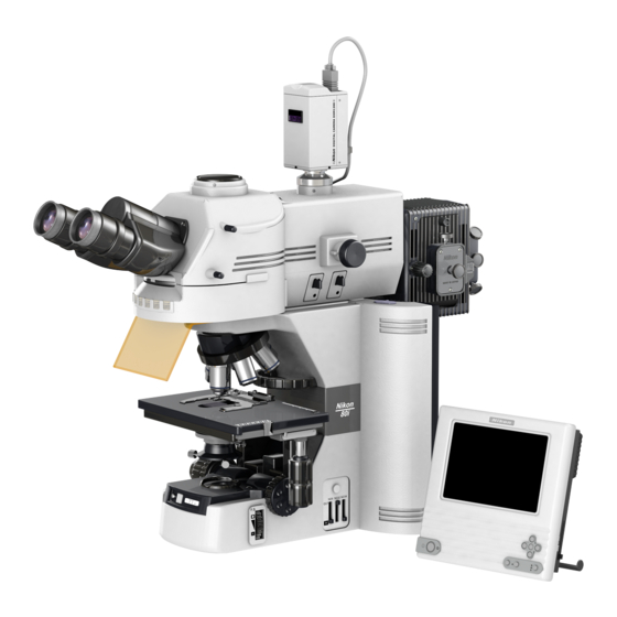
Part Names and Microscopy Procedures (Bright-Field Set) Names of Main Components Eyepiece tube Eyepiece Camera head (Required for image capture) (One example shown in the photo) DSC port (Required for image capture) Revolving nosepiece Objective Lamphouse Specimen holder Stage Condenser Microscope (main body) Camera control unit (Required for image capture) -
Page 17: Names Of Parts Used To Make Adjustments
Chapter 1 Part Names and Microscopy Procedures (Bright-Field Set) 1.2 Names of Parts Used to Make Adjustments Names of Parts Used to Make Adjustments Right view 1.2.1 Diopter adjustment ring Optical path switching lever Aperture diaphragm lever Y stage knob X stage knob (Provided on the left side in certain products) -
Page 18: Left View
Chapter 1 Part Names and Microscopy Procedures (Bright-Field Set) 1.2 Names of Parts Used to Make Adjustments Left view 1.2.2 Condenser focus knob Coarse focus (Provided on the torque adjustment right side in knob certain products) Coarse focus knob Condenser Fine focus knob centering screw... -
Page 19: Ergonomic Binocular Tube With Camera Attached
Chapter 1 Part Names and Microscopy Procedures (Bright-Field Set) 1.2 Names of Parts Used to Make Adjustments Ergonomic binocular tube with camera attached 1.2.4 Camera cable connector Camera head C mount Camera fine focus adjustment screw Camera centering screws... -
Page 20: Bright-Field Microscopy
Chapter 1 Part Names and Microscopy Procedures (Bright-Field Set) 1.3 Bright-Field Microscopy Bright-Field Microscopy Turn on power. Press the power switch to the "|" position. Press the preset switch. Press the preset switch. Move the ND8, ND32, and NCB11 filters into the optical path. NCB11 ND32 The full optical... - Page 21 Chapter 1 Part Names and Microscopy Procedures (Bright-Field Set) 1.3 Bright-Field Microscopy Raise the condenser to the uppermost position. Raise the condenser using the condenser focus knob. Fully open the field diaphragm and aperture diaphragm. (When using the 1-100x condenser, move the top lens into the optical path.) Fully open the field Fully open the...
-
Page 22: Interpupillary Distance
Chapter 1 Part Names and Microscopy Procedures (Bright-Field Set) 1.3 Bright-Field Microscopy Focus on the specimen. Focus on the specimen using the coarse and fine focus knobs. Adjust the diopter and the interpupillary distance. Refer to "8. Diopter Adjustment" and "9. Interpupillary Distance Adjustment"... - Page 23 Chapter 1 Part Names and Microscopy Procedures (Bright-Field Set) 1.3 Bright-Field Microscopy Switch to the desired objective and view the specimen. Adjust the field diaphragm and aperture diaphragm each time you change objectives. Field diaphragm: Select the Set slightly narrower than the margins of desired objective.
-
Page 24: Photomicroscopy
Chapter 1 Part Names and Microscopy Procedures (Bright-Field Set) 1.4 Photomicroscopy Photomicroscopy For detailed explanations of the camera, photomicroscopic software, and PC, refer to the operating manuals provided with the respective products. The following instructions assume a DS-5M digital camera and DS-L1 camera control unit. Adjust the microscope for proper image observation. - Page 25 Chapter 1 Part Names and Microscopy Procedures (Bright-Field Set) 1.4 Photomicroscopy Select the camera scene mode suitable for the microscopy method. Set the camera white balance. To adjust white balance, press the WB button while capturing an image of a clear section of a specimen slide.
-
Page 26: Chapter 2 Part Names And Microscopy Procedures (With Epi-Illumination Attachment Mounted)
Part Names and Microscopy Procedures (With Epi-illumination Attachment Mounted) Names of Main Components Camera head (Required for image capture) (One example shown in the photo) Eyepiece tube Photographic vertical tube adapter Eyepiece (Required for image capture) Epi-illumination lamphouse (The Epi-illumination attachment uses a mercury, Epi-illumination xenon, or high-intensity... -
Page 27: Names Of Parts Used To Make Adjustments
Chapter 2 Part Names and Microscopy Procedures (With Epi-illumination Attachment Mounted) 2.2 Names of Parts Used to Make Adjustments Names of Parts Used to Make Adjustments Right view 2.2.1 Camera cable Camera head C mount adapter C mount adapter retaining screw Optical path switching lever Diopter adjustment... -
Page 28: Left View
Chapter 2 Part Names and Microscopy Procedures (With Epi-illumination Attachment Mounted) 2.2 Names of Parts Used to Make Adjustments Left view 2.2.2 Condenser focus knob Coarse focus torque (Provided on adjustment knob the right side in certain products) Coarse focus knob Condenser Fine focus knob... -
Page 29: Bright-Field Microscopy
Chapter 2 Part Names and Microscopy Procedures (With Epi-illumination Attachment Mounted) 2.3 Bright-Field Microscopy Bright-Field Microscopy Turn on power. Press the power switch to the "|" position. Press the preset switch. Press the preset switch. Move the ND8, ND32, and NCB11 filters into the optical path. - Page 30 Chapter 2 Part Names and Microscopy Procedures (With Epi-illumination Attachment Mounted) 2.3 Bright-Field Microscopy Rotate the excitation method switchover turret to set it at position where no filter cube is installed. Rotate the excitation method switchover turret. Raise the condenser to the uppermost position.
- Page 31 Chapter 2 Part Names and Microscopy Procedures (With Epi-illumination Attachment Mounted) 2.3 Bright-Field Microscopy Set a specimen and secure in Set a specimen and move the place using the specimen holder. portion to be viewed into the optical path. Move the portion to be viewed into the optical path using the XY stage knobs.
- Page 32 Chapter 2 Part Names and Microscopy Procedures (With Epi-illumination Attachment Mounted) 2.3 Bright-Field Microscopy Switch to the desired objective and view the specimen. Adjust the field diaphragm and aperture diaphragm each time you change objectives. Select the desired objective. Field diaphragm: Set slightly narrower than the margins of the field of view.
-
Page 33: Epi-Fluorescence Microscopy
Chapter 2 Part Names and Microscopy Procedures (With Epi-illumination Attachment Mounted) 2.4 Epi-fluorescence Microscopy Epi-fluorescence Microscopy Before microscopy... • Check the cumulative operating hours of the lamp in the Epi-illumination attachment. Replace the lamp if its cumulative operating hours exceed the recommended maximum service life. - Page 34 Chapter 2 Part Names and Microscopy Procedures (With Epi-illumination Attachment Mounted) 2.4 Epi-fluorescence Microscopy Fully open the field diaphragm and aperture diaphragm of the Epi-illumination attachment. Fully open the field Fully open the diaphragm. aperture diaphragm. Switch on power for the light source of the Epi-illumination attachment, then open the shutter and center the lamp.
- Page 35 Chapter 2 Part Names and Microscopy Procedures (With Epi-illumination Attachment Mounted) 2.4 Epi-fluorescence Microscopy Focus on the specimen. Focus on the specimen using the coarse and fine focus knobs. Center the field diaphragm of the Field diaphragm open/close lever Epi-illumination attachment. Refer to "4.
- Page 36 Chapter 2 Part Names and Microscopy Procedures (With Epi-illumination Attachment Mounted) 2.4 Epi-fluorescence Microscopy To return to bright-field microscopy • Close the shutter of the Epi-illumination attachment and block the epifluorescent light. • Rotate the excitation method switchover turret to move the position where no fluorescent Close the shutter.
-
Page 37: Photomicroscopy
Chapter 2 Part Names and Microscopy Procedures (With Epi-illumination Attachment Mounted) 2.5 Photomicroscopy Photomicroscopy For detailed discussions of the camera, photomicroscopic software, and PC, refer to the operating manuals provided with the respective products. The following instructions assume a DS-5M digital camera and DS-L1 camera control unit. Adjust the microscope for proper image observation. - Page 38 Chapter 2 Part Names and Microscopy Procedures (With Epi-illumination Attachment Mounted) 2.5 Photomicroscopy Make camera settings. For a detailed discussion of this topic, refer to the operating manual provided with the camera. When using the DS-L1, you must choose and enter at least the following information: •...
-
Page 39: Chapter 3 Part Names And Microscopy Procedures(With Dih-M Mounted))
Part Names and Microscopy Procedures (With DIH-M Mounted) Names of Main Components Camera head (Required for image capture) (One example shown in the photo) Eyepiece DIH-M Epi-illumination lamphouse (The Epi-illumination attachment uses a mercury, xenon, or high-intensity halogen lamp as its light source. -
Page 40: Names Of Parts Used To Make Adjustments
Chapter 3 Part Names and Microscopy Procedures(With DIH-M Mounted) 3.2 Names of Parts Used to Make Adjustments Names of Parts Used to Make Adjustments Right view 3.2.1 C mount adapter C-mount adapter retaining screw Optical path Camera cable switching lever (1) Optical path Camera head switching lever (2) -
Page 41: Left View
Chapter 3 Part Names and Microscopy Procedures(With DIH-M Mounted) 3.2 Names of Parts Used to Make Adjustments Left view 3.2.2 DIH-M Power ON indicator ND4 filter slider ND8 filter slider ND16 filter slider Condenser focus knob Coarse focus torque (Provided on adjustment knob the right side in certain... -
Page 42: Rear View (Without Accessory Device)
Chapter 3 Part Names and Microscopy Procedures(With DIH-M Mounted) 3.2 Names of Parts Used to Make Adjustments Rear view (without accessory device) 3.2.3 Tool storage compartment C-Box mounting sections Power switch Lamphouse AC inle connector port Input voltage indication Lamphouse mounting section C-Box power switch Intelligent nosepiece... -
Page 43: Bright-Field Microscopy
Chapter 3 Part Names and Microscopy Procedures(With DIH-M Mounted) 3.3 Bright-Field Microscopy Bright-Field Microscopy Turn on power. The C-Box and the power source for the Epi-illumination do not need to be turned on. If they are turned on, keep the shutter of the Epi-illumination closed. - Page 44 Chapter 3 Part Names and Microscopy Procedures(With DIH-M Mounted) 3.3 Bright-Field Microscopy Rotate the excitation method switchover turret to set it a position where no fluorescent cube is installed. Rotate the excitation method switchover turret. Raise the condenser to the uppermost position.
- Page 45 Chapter 3 Part Names and Microscopy Procedures(With DIH-M Mounted) 3.3 Bright-Field Microscopy Set a specimen and secure in Set a specimen and move the place using the specimen holder. portion to be viewed into the optical path. Move the portion to be viewed into the optical path using the XY stage knobs.
- Page 46 Chapter 3 Part Names and Microscopy Procedures(With DIH-M Mounted) 3.3 Bright-Field Microscopy Focus and center the condenser. Refer to "11. Adjustment of Condenser Position" in the separate Reference manual. Focus the condenser using Center the condenser the condenser focus knob. using the condenser centering screws.
-
Page 47: Epi-Fluorescence Microscopy
Chapter 3 Part Names and Microscopy Procedures(With DIH-M Mounted) 3.4 Epi-fluorescence Microscopy Epi-fluorescence Microscopy Before microscopy... • Check the cumulative operating hours of the lamp in the Epi-illumination attachment. Replace the lamp if its cumulative operating hours exceed the recommended maximum service life. •... - Page 48 Chapter 3 Part Names and Microscopy Procedures(With DIH-M Mounted) 3.4 Epi-fluorescence Microscopy Switch on power for the C-Box and Epi-illumination light source. (Note that the shutter for the C-Box Epi-illumination is closed power switch automatically.) Press the hand switch to open Push to open the shutter.
- Page 49 Chapter 3 Part Names and Microscopy Procedures(With DIH-M Mounted) 3.4 Epi-fluorescence Microscopy Focus on the specimen. Focus on the specimen using the coarse and fine focus knobs. Center the field diaphragm of the Field diaphragm open/close lever Epi-illumination attachment. Refer to "4. Epi-fluorescent Field Diaphragm" in "17.
- Page 50 Chapter 3 Part Names and Microscopy Procedures(With DIH-M Mounted) 3.4 Epi-fluorescence Microscopy To return to bright-field microscopy. • Close the shutter of the Epi-illumination and block the Epi-illumination. • Rotate the excitation method switchover turret to move the position where no filter Use the excitation method switchover cube is installed into the optical path.
-
Page 51: Photomicroscopy
Chapter 3 Part Names and Microscopy Procedures(With DIH-M Mounted) 3.5 Photomicroscopy Photomicroscopy For detailed discussions of the camera, photomicroscopic software, and PC, refer to the operating manuals provided with the respective products. The following instructions assume a DS-5M digital camera and DS-L1 camera control unit. Adjust the microscope for proper image observation. - Page 52 Chapter 3 Part Names and Microscopy Procedures(With DIH-M Mounted) 3.5 Photomicroscopy Select the camera scene mode suitable for the microscopy method. Set the camera white balance. To adjust white balance, press the WB button while capturing an image of a clear section of a specimen slide.
-
Page 53: Chapter 4 Assembly
Input voltage Note: If the voltage indication and supply voltage indication differ, do not attempt to use the microscope. Contact your nearest Nikon representative to seek advice. Back Installing a Lamp Lamphouse-cover fixing screw Loosen the lamphouse-cover fixing screw and lift the lamphouse cover to remove. - Page 54 Chapter 4 Assembly Attaching the lamphouse Attaching the lamphouse (1) Attach the lamphouse to the back of the microscope and fix it with the fixing screw. (2) Attach the connector. Fixing screw Attaching the connector Installing a Stage (1) Turn the coarse focus knob to remove the cushioning material from the elevating section.
- Page 55 Chapter 4 Assembly (2) Place the stage on the elevating section and fix into place with two screws. (For the stage with a centering function, place the stage on the elevating section by aligning the projection on the back of the stage with the groove of the elevating section.) Fixing the stage Screws fixing the stage...
- Page 56 Chapter 4 Assembly Installing a Condenser Condenser focus knob (1) Turn the coarse focus handle until the elevating section is raised to the highest position. (2) Turn the condenser focus knob until the elevating section is brought to the lowermost position.
- Page 57 Chapter 4 Assembly Installing an Epi-illumination attachment Screws to fix the Epi-illumination (1) Place an Epi-illumination attachment on the attachment (three screws in total) microscope arm and fix it with a screw at the front of the arm. (2) Secure in place with two screws at the back of the Epi-illumination attachment.
- Page 58 Chapter 4 Assembly Using the DIH-M (1) Attach two C-BOXs to the back of the microscope with screws. C-BOX fixing (2) Place the DIH-M on the microscope arm and fix it with a screw at the front of the arm. Cover fixing screw (3) Remove the back cover of the DIH-M by loosening the two screws.
- Page 59 Chapter 4 Assembly Fixing screws for optical (7) Connect the control cable attached to the path switching section DIH-M to the C-BOX. 1) Remove the cover on the left side of the DIH-M. 2) Loosen the optical path switching section fixing board mount screw.
- Page 60 Chapter 4 Assembly (10) Attach the mercury lamphouse to the back of Bayonet mount the bayonet mount. (For more information, refer to the instruction manual provided with the super high-pressure mercury lamp power supply.) 1) Attach a collector lens to the lamphouse. 2) Turn the bayonet mount clockwise (viewed from the back) as far as it will go.
-
Page 61: Installing Objectives
Chapter 4 Assembly Installing a Revolving Nosepiece Fixing the revolving nosepiece (1) Lift the revolving nosepiece from a position just forward of the point directly below the fitting part and slide toward the back to attach. (Continue sliding the revolving nosepiece until its front position is aligned with that of the fitting part.) (2) Secure with the screw. - Page 62 Chapter 4 Assembly Installing Filter Cubes and a Light Shield (when the Epi-illumination attachment or the DIH-M is installed) (1) There is a front cover below the eyepiece. Pull Address Excitation switching turret out the cover to remove. indication (2) Insert a filter cube into position. Filter cube Filter cube fitting part (3) Insert a nameplate into the position with the...
- Page 63 Chapter 4 Assembly Installing a Camera (when using a camera) 12-1 When attaching to the ergonomic binocular tube: Camera head (1) To attach a camera head, screw it into the C mount on the DSC port. (2) Remove the rear cover of the ergonomic binocular tube and insert the DSC port.
- Page 64 Chapter 4 Assembly Installing the Power Cord (1) Check to confirm that the microscope power switch is off. (2) Insert one end of the power cord into the AC inlet at the back of the microscope. Power switch for the (3) Insert the other end of the power cord into microscope the wall outlet.
-
Page 65: Chapter 5 Replacing Consumables
Replacing Consumables Replacing the lamp CAUTION • Be careful to avoid burns: Wait until the lamp and nearby parts have cooled before attempting to replace the lamp. • Be careful to avoid electrical shock: Turn off the power switch and unplug the power cord from the outlet. •... -
Page 66: Chapter 6 Troubleshooting
Cover glass thickness not as specified Poor contrast Tip pf the oil-immersed objective Poor resolution not immersed in oil Use Nikon immersion oil. Unspecified immersion oil used Air bubbles in immersion oil Remove the air bubbles. Immersion oil attached to tip of the Clean. -
Page 67: Electrical
Chapter 6 Troubleshooting 6.2 Electrical Problem Possible causes Remedy Revolving nosepiece not installed Install correctly and rotate to the click correctly, or not rotated to the click stop position. stop position Image flows Specimen projecting from the stage Securely attach the specimen to the surface stage specimen holder. -
Page 68: Chapter 7 Cleaning And Maintenance
Cleaning and Maintenance Lens cleaning Keep the lens free of dust, fingerprints, etc. Dirt on the lenses or filters will affect image quality. If any of the lenses become dirty, clean them by the procedure given below. Brush away dust with a soft brush or wipe away gently with gauze. •... -
Page 69: Storage
Periodic inspections (fee charged) To maintain the peak performance of the microscope, we recommend periodic inspections. Contact your nearest Nikon representative for more information. (Parts and service charges apply for this service.) -
Page 70: Chapter 8 Specifications
Specifications Specifications Nikon Microscope ECLIPSE 80i Model ECLIPSE 80i Main unit Optical system CFI60 system (infinity-corrected CF optical system) Main unit T-shaped, double-winged Illumination system Flyeye illumination, power supply incorporated, with preset feature 12V/100W long-life halogen lamp (specified lamp housing: D-CH precentered lamp housing) - Page 71 Chapter 8 Specifications 8.1 Specifications • 100-120V regions Power cord UL-listed detachable power cord set (3 conductor grounding Type SVT, AWG 18, 3m long maximum, rated at 125V AC minimum) • 230V areas EU/EN-approved 3-conductor power cord set (3 conductor grounding Type H05VV-F, AWG 18, 3m long maximum, rated at 250V AC minimum) Operating conditions Temperature: 0 to 40°C...
- Page 72 Chapter 8 Specifications 8.1 Specifications D-DH Digital Imaging Head M for Nikon Microscopes Model D-DH Digital Imaging Head M Optical system Infinity-corrected CF optical system Eyepiece lens field number: φ25mm Variable intermediate magnification: Binocular tube 1X Front port 1x Rear port 0.8 to 2x (zoom ratio: 2.5, manual, with intelligent feature)