Table of Contents
Advertisement
Advertisement
Table of Contents

Related Manuals for Nikon SMZ745T


Summary of Contents for Nikon SMZ745T
- Page 1 M518E 09.7.NF.1 Stereoscopic Zoom Microscope SMZ745T Instructions...
-
Page 3: Introduction
Introduction Thank you for purchasing a Nikon product. This instruction manual is written for users of Nikon Stereoscopic Zoom Microscope SMZ745T. To ensure correct usage, read this manual carefully before operating the product. • No part of this manual may be reproduced or transmitted in any form without prior written permission from Nikon. -
Page 4: Safety Precautions
Safety Precautions To ensure correct and safe operation, read this manual before using the product. Warning/Caution Symbols Used in this Manual Although this product is designed and manufactured to be completely safe during use, incorrect usage or failure to follow the safety instructions provided may cause personal injury or property damage. -
Page 5: Warning
When using an illuminator, check that the input voltage displayed on the power supply of the illuminator matches the operating voltage. Please contact your nearest Nikon representative if the displayed voltage does not match the operating voltage. Use of an improperly matched illuminator may result in damage to the equipment. -
Page 6: Caution
WARNING 6. Cautions on heat from the light source The lamp and the lamphouse become extremely hot when the lamp is turned on. Follow the cautions below to prevent burns and fire. • To avoid burns, do not touch the lamp and the lamphouse while the lamp is on or for approximately thirty minutes after it has been turned off. -
Page 7: Notes On Handling The Product
Safety Precautions Notes on Handling the Product 1. Handle with care. This stereoscopic microscope is a precision optical instrument. Handle the product with care and avoid physical shocks. Physical shocks during transportation and operation as well as forcible operations may result in damage to the product. 2. - Page 8 • Put a dust-proof cover over the product to protect it from dust. 6. Regular inspections (Paid service) Regular inspections are recommended in order to maintain the peak performance. Please consult your nearest Nikon representative for details about regular inspections.
-
Page 9: Table Of Contents
Contents Introduction ................... 1 Safety Precautions ................ 2 Warning/Caution Symbols Used in this Manual ........2 WARNING ................3 CAUTION ................4 Notes on Handling the Product ............5 Nomenclature ................8 Microscopy Procedures ............10 1. Place the sample..............10 2. -
Page 10: I Nomenclature
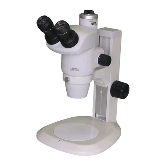
Nomenclature The illustration shows the combination of SMZ745T zooming body, C-W10X eyepieces and C-PS plain focusing stand. C mount fixing screw C mount cap The direction of DS camera head can be C mount adjusted by Nikon DS camera loosening the fixing... - Page 11 Zooming knob clicks ON/OFF screw (inside) Refer to “ON/OFF of the zooming knob clicks.” on p.11 Eyepiece inclination Hexagonal wrench 45° from the horizontal hanger Stores the supplied hexagonal wrenches. Hexagonal wrench (Large) Supplied with the focusing stand for Screw hole for mounting an changing the arm for halogen illuminator height of the arm.
-
Page 12: Microscopy Procedures
The distance between the focus plane and the bottom surface of the zooming body is called “the working distance”. Since the working distance of the SMZ745T is 115 mm, the focusing will become easier if you set the zooming body at the position where its bottom surface is 115 mm apart from the sample surface. -
Page 13: Adjust The Diopter
Adjust the diopter. This adjustment is for adjusting the eyesight of the observer. 1 Turn the diopter rings on both eyepieces to set them at the 0 position (match the 0 line with the index line). 2 Turn the zooming knob to 5X. Focus on the sample using the focus knob. -
Page 14: Change The Optical Path
Right eyepiece : Vertical tube backward. =100 : 0 Please refer to the instruction of the camera head for the details of the Nikon DS Camera Head operation. Right eyepiece : Vertical tube =100 : 0 ☞... -
Page 15: Assembly
Assembly Place the stand on the level surface. Mount the stage plate. Press the stage plate into the stand base while pushing it against the rim in the direction shown by the arrow in the illustration. The stand arm can be lowered. (For not lowering the arm, jump to Groove step 4.) - Page 16 Insert the eyepieces into the eyepiece sleeves. Be sure that it is inserted all the way to the end of the sleeve. Note) When inserting the 10X eyepiece, assure that it reaches the end of the sleeve, because the rubber cover of the 10X eyepiece will obstruct the view of the sleeve end.
-
Page 17: Antistatic Feature
Assembly Antistatic Feature The SMZ745T, the C-PS/C-PSC plain focusing stand and the C-W10X eyepieces are antistatic. You can enjoy this feature when observing the sample that cannot stand much static. When using the microscope on this purpose, change the stage plate to antistatic ESD stage plate and ground the microscope through the ground jack at the rear of the plain focusing stand. -
Page 18: Using Accessories
Using Accessories Reticles Your reticles can be attached to the eyepiece. Remove the field ring (or lens room of the 20X and 30X) from the eyepiece, then attach the reticle with its pattern surface facing down to the eyepiece, and reattach the field ring (or lens room). -
Page 19: Halogen Illuminators
Halogen Illuminators There are two illuminators available: the G-LS of 6V10W and the C-DSLS of 6V20W. G-LS Lamp Socket A (6V10W) Lamp socket Plug (Removable back and forth) Lamphouse Mounting screw C-DSLS Illuminator A (6V20W) Lamphouse Lamp socket Plug Filter cap ø33 mm filter attachable Holder and Epi arm... - Page 20 Pull the lamp socket from the lamphouse and insert the lamp straight into the socket to the end. Use halogen lamps of the specified rating only. Then, attach the lamp socket to the lamphouse. G-LS Socket Lamp (GE 787 6V-10W) C-DSLS Confirmation window...
- Page 21 Using Accessories Attaching to the stand (for G-LS only) Align the protrusion on the lamphouse with G-LS the inside of the screw hole on the arm of the stand (screw hole for mounting 6V10W halogen illuminator), then insert the mounting screw from the outside of the arm and secure Mounting screw...
- Page 22 2 Epi arm Slightly loosen the clamp knob on the Clamp knob Simultaneously arm. Screw in the mounting screw at clamps two the end of the Epi arm into the left or arms/joints. right screw hole (for mounting an arm Joint for halogen illuminator) on the arm of the stand while turning the joint.
-
Page 23: Power Supplies
Always use the specified voltage used in your area. If the voltages do fuse (250 V, 1 A). not match, do not use the power supply and contact your nearest Nikon representative. (Rear view) Power cord Output connector Power switch... - Page 24 Check that the voltage displayed matches the voltage used in your area. If the voltages do brightness when rotated. not match, do not use the power supply and contact your nearest Nikon representative. Output connector Connect the lamphouse cable here.
- Page 25 Table 1...
-
Page 26: Table 2: Total Magnification And Real Field Of Vertical Tube
Table 2, Table 3 Table 2: Total Magnification and Real Field of Vertical Tube Vertical tube Auxiliary Working 0.55 X objective distance Field number 11 [mm] Total magnification Real field [mm] None 0.37 to 2.75 29.9 to 4.0 AL0.29 X 0.11 to 0.80 102.9 to 13.8 AL0.5 X...