Table of Contents
Advertisement
Quick Links
Advertisement
Chapters
Table of Contents

Related Manuals for Nikon Eclipse Ti-E


Summary of Contents for Nikon Eclipse Ti-E
- Page 1 M450 E 07.10.NF.1 Inverted Microscope Instructions...
-
Page 3: Introduction
Introduction Thank you for purchasing a Nikon product. This instruction manual is written for users of Nikon Inverted Microscope Eclipse Ti-E and Ti-E/B. To ensure correct usage, read this manual carefully before operating the product. • No part of this manual may be reproduced or transmitted in any form without prior written permission from Nikon. -
Page 4: Safety Precautions
Safety Precautions To ensure correct and safe operation, read this manual before using the product. Warning and Caution Symbols in this Manual Although this product is designed to be completely safe during use, incorrect usage or failure to follow the safety instructions provided may cause personal injury or property damage. -
Page 5: Led Safety
Safety Precautions LED Safety The PFS Motorized Nosepiece (TI-ND6-PFS Perfect Focus Unit) uses light in the near-infrared region (IR wavelength) emitted from an infrared LED to control the focus. When using the PFS Motorized Nosepiece with the product, the microscope system conforms to the EU standard EN60825-1: 2001 and the international standard IEC60825-1: 2001. - Page 6 If the indicated input voltage does not match your regional voltage supply, do not use the power supply device, and contact Nikon. Use of a power supply device with the inappropriate voltage rating may result in overheating or fire due to overcurrent, and may also cause damage the power supply device and connected devices.
- Page 7 Safety Precautions Warning Cautions on the power cord Be sure to use the specific power cords for the AC adapter and the power supply device. Use of other power cords may result in malfunction, overheat, or fire. • See Chapter 7, “Specifications” for the specified power cord. •...
- Page 8 12. Notes on handling flammable solvents The following flammable solvents are used with the product: • Immersion oil (Nikon Immersion Oil for oil immersion objectives) • Absolute alcohol (ethyl alcohol or methyl alcohol for cleaning optical parts) •...
- Page 9 Then, wipe off the liquid with a piece of dry cloth. Intrusion of foreign matters into the product may also result in malfunctions. If liquids or foreign matters enter the product, do not use the product, and contact Nikon. Weak electromagnetic waves The product emits weak electromagnetic waves.
-
Page 10: Notes On Handling The Product
Safety Precautions Notes on Handling the Product Handle with care. The product is a precision optical instrument. Handle the product with care and avoid physical shocks and vibrations. In particular, the precision of objectives may be lost by even weak physical shocks. Installation location and storage location The product is a precision optical instrument. - Page 11 Safety Precautions Notes on using the focus knobs • Never rotate the left and right focus knobs on the microscopes in the opposite directions at the same time. Doing so may damage the product. • Do not rotate the focus knobs past their limit. Doing so may damage the product. Protecting the ports.
-
Page 12: Table Of Contents
Contents Introduction..............................1 Safety Precautions ............................2 Warning and Caution Symbols in this Manual ......................2 Symbols on the Product ............................. 2 LED Safety ................................. 3 Notes on Handling the Product ..........................8 Contents ................................11 Part Names............................. 12 Ti-E, Ti-E/B..............................13 Microscope Base ............................ -
Page 13: Contents
Contents 3.8.2 ELWD-S Condenser ........................67 Eyepiece Tube Operation ..........................68 3.9.1 Diopter Adjustment ......................... 68 3.9.2 Interpupillary Distance Adjustment ....................68 3.9.3 Eyepiece Tube Shutter Operation ....................69 3.9.4 Bertrand Lens Operation ........................ 69 3.10 Focusing Mechanism Operation ........................70 3.10.1 Focus Knob Operation ........................ -
Page 14: Part Names
Part Names This chapter describes the name of each part of the product. When using the product for the first time, refer to this chapter and check the name and the position of each part. Also refer to this chapter for names and positions of the controls whenever necessary. •... -
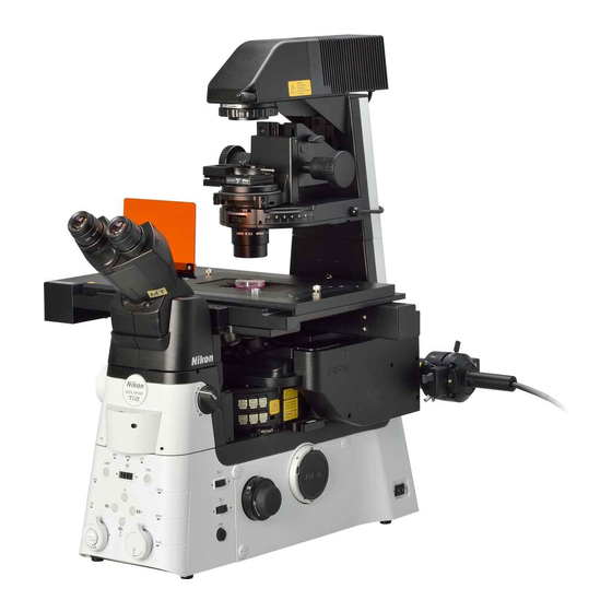
Page 15: Ti-E, Ti-E/B
Chapter 1 Part Names 1.1 Ti-E, Ti-E/B Ti-E, Ti-E/B The illustrations below show the Ti-E microscope body with the following accessories: TI-DH Dia Pillar Illuminator 100W, TI-C Condenser Turret, D-LH/LC Precentered Lamphouse LC, 12V 100W halogen lamp, TI-PS100W Power Supply, TI-SR Rectangular Mechanical Stage, TI-T-B Eyepiece Base Unit, TI-TD Eyepiece Tube B, CFI 10x eyepieces, TI-ND6-PFS Perfect Focus Unit, objectives, etc. -
Page 16: Microscope Base
Chapter 1 Part Names 1.2 Microscope Base Microscope Base 1.2.1 Microscope Base To keep out extraneous light and dust, be sure to attach the provided caps to all ports not in use. Nosepiece mount Dia pillar illuminator mount (A carrying handle is attached for transportation.) Cover Analyzer slot... -
Page 17: Operation Panels
Chapter 1 Part Names 1.2 Microscope Base 1.2.2 Operation Panels Front operation panel Status display panel (20x2) DISPLAY switches Z-RESET switch (display item selector) (Z-axis position reset) BRIGHTNESS switch PFS control switches/indicators (display brightness selector) BRIGHTNESS Z - RESET • FOCUS indicator DISPLAY Optical path selector switches/indicators FOCUS... -
Page 18: Connector Panels
Chapter 1 Part Names 1.2 Microscope Base 1.2.3 Connector Panels Right connector panel OFFSET connector PFS connector (for PFS offset controller) (for PFS motorized nosepiece) OFFSET PIEZO INTERLOCK PIEZO connector INTERLOCK connector (for PIEZO motorized stage) (for external laser controller) Figure 1-8 Right connector panel Rear connector panel Grooves for... -
Page 19: Eyepiece Base Unit, Eyepiece Tube, And Eyepieces
Chapter 1 Part Names 1.3 Eyepiece Base Unit, Eyepiece Tube, and Eyepieces Eyepiece Base Unit, Eyepiece Tube, and Eyepieces The following eyepiece base units, eyepiece tubes, and eyepieces can be mounted on the observation port of the microscope. TI-T-B Eyepiece Base Unit This is a basic type eyepiece tube base. - Page 20 Chapter 1 Part Names 1.3 Eyepiece Base Unit, Eyepiece Tube, and Eyepieces TI-TS Eyepiece Tube B This is a basic type eyepiece tube. Eyepiece (both sides, sold separately) Binocular part Figure 1-13 TI-TS Eyepiece Tube B TI-TD Eyepiece Tube B This is an eyepiece tube with a manual shutter and a Eyepiece (both sides,...
-
Page 21: Pfs Motorized Nosepiece And Pfs Offset Controller
Chapter 1 Part Names 1.4 PFS Motorized Nosepiece and PFS Offset Controller PFS Motorized Nosepiece and PFS Offset Controller The PFS Motorized Nosepiece (TI-ND6-PFS Perfect Focus Unit) is an integrated combination of a motorized sextuple DIC nosepiece and a perfect focus system (PFS). The offset can be controlled with the PFS Offset Controller. -
Page 22: Stage
Chapter 1 Part Names 1.5 Stage Stage The following stages can be attached to the product. TI-SR Rectangular Mechanical Stage The specimen can be moved in the X and Y Stage ring directions by operating the stage knob. (concentric ring) The rectangular mechanical stage comes with two stage clips for culture vessels, and the following two concentric rings. -
Page 23: Dia Pillar Illuminator
Chapter 1 Part Names 1.6 Dia Pillar Illuminator Dia Pillar Illuminator Ti series microscopes can be used with the following two types of dia pillar illuminators. The two dia pillar illuminators differ in lamp rating (12V 100W or 6V 30W) and support different microscopy methods. Select the dia pillar illuminator to suit your application. -
Page 24: Condenser
Chapter 1 Part Names 1.7 Condenser Condenser 1.7.1 TI-C Condenser Turret (System Condenser) The TI-C Condenser Turret allows you to attach various optical elements to a turret and select them as necessary for different microscopy methods. This type of condenser is referred to as a “system condenser”. System condenser (mounted on TI-DH Dia Pillar Illuminator 100W) Condenser focus knob Condenser focus knob... -
Page 25: Elwd-S Condenser
Chapter 1 Part Names 1.7 Condenser 1.7.2 ELWD-S Condenser The ELWD-S Condenser supports bright-field Centering knob microscopy and phase contrast microscopy. It can Clamp screws be used with both 100W and 30W dia pillar (both sides) illuminators. Condenser centering knobs (both sides) Turret Condenser lens... -
Page 26: Power Supply
Chapter 1 Part Names 1.8 Power Supply Power Supply 1.8.1 TI-PS100W Power Supply Warning The bottom of the power supply device becomes hot during use. Do not block the air vents on the side of the product. POWER indicator 12VDC output connector Brightness EXTERNAL connector... -
Page 27: Te-Ps30W Power Supply A (For 100-120V) Te-Pse30 Power Supply A (For 220-240V)
Before turning on the power supply, check that the input voltage indicator matches the power voltage in your area. If the voltages do not match, do not turn on the product, and contact Nikon. Use of the product under a wrong voltage may result in malfunction or fire. •... -
Page 28: Ac Adapter
Chapter 1 Part Names 1.9 AC Adapter AC Adapter Power to the microscope is supplied via an AC AC adapter adapter. The AC adapter can be used with 100 to 240 VAC at 50-60 Hz, and can be used with most wall outlets in the world. -
Page 29: Microscopy
Microscopy Warning • Before using the product, thoroughly read the “Safety Precautions” at the beginning of this manual, and heed all warnings and cautions written therein. • To use other equipment such as epi-fl attachment or differential interference contrast attachment, refer to the respective manuals and heed all warnings and cautions written therein. -
Page 30: Introduction To Microscopy
Chapter 2 Microscopy 2.1 Introduction to Microscopy Introduction to Microscopy The Ti series microscopes are system microscopes that offer a high degree of flexibility in system building for various purposes. A wide range of options is available for various parts, including the main body, dia illuminator, and eyepiece tube. - Page 31 Chapter 2 Microscopy 2.1 Introduction to Microscopy Sample configuration This section describes the microscopy procedures under the assumption that the following devices are attached to the microscope. 1. Ti-E microscope body 2. AC adapter, power cord * 3. TI-T-B Eyepiece Base Unit 4.
-
Page 32: Bright-Field (Bf) Microscopy
Chapter 2 Microscopy 2.2 Bright-Field (BF) Microscopy Bright-Field (BF) Microscopy Bright-field (BF) microscopy workflow Outline: Remove all unnecessary optical elements from the optical path. Focus and center the condenser. Adjust the aperture diaphragm for a better image. Reset convenient functions. Page 31 Turn on the dia illuminator. -
Page 33: Reset Convenient Functions
Chapter 2 Microscopy 2.2 Bright-Field (BF) Microscopy Reset convenient functions. 1. Release the condenser refocusing clamp on the dia pillar illuminator by rotating it counterclockwise. 2. Open the shutter at the eyepiece by pushing in the shutter operation lever on the right side of the eyepiece tube. -
Page 34: Adjust The Illumination For Optimal Color Reproduction
Chapter 2 Microscopy 2.2 Bright-Field (BF) Microscopy Adjust the illumination for optimal color reproduction. 1. Rotate the brightness control knob on the left 3-2, 3-3 side of the microscope to the “12V100W” position. 2. Move the NCB11 filter on the dia pillar illuminator into the optical path. -
Page 35: Set Up For Bright-Field Microscopy
Chapter 2 Microscopy 2.2 Bright-Field (BF) Microscopy Set up for bright-field microscopy. 1. Move the condenser cassette for bright-field microscopy into the optical path by rotating the condenser turret to position “A”. Set specimen and adjust the focus. 1. Place the specimen onto the stage. 2. -
Page 36: Adjust The Diopters And The Interpupillary Distance
Chapter 2 Microscopy 2.2 Bright-Field (BF) Microscopy Adjust the diopters and the interpupillary distance. 1. On each eyepiece, rotate the diopter adjustment ring to align its lower end with the marking on the eyepiece. This will be the reference position for diopter 7-1, 7-5, adjustment. -
Page 37: Center The Condenser
Chapter 2 Microscopy 2.2 Bright-Field (BF) Microscopy Center the condenser. 1. Check that the 10x objective is in the optical path. The status display panel can be used to confirm 9-2, 9-6 which objective is in the optical path. 9-4, 9-7 Display example for objective (10x, NA 0.25) _ _ _ _ _ _ _ _ _ _ _ _ 1 0 x / 0 . -
Page 38: Observe The Specimen
Chapter 2 Microscopy 2.2 Bright-Field (BF) Microscopy Observe the specimen. 1. Move an objective with the desired 10-4 magnification into the optical path by pressing the Obj. switch. 10-3 2. Adjust the size of the aperture diaphragm to 10-2 “70-80% the size of the NA of the objective” by moving the aperture diaphragm open/close lever on the system condenser. -
Page 39: Change The Specimen
Chapter 2 Microscopy 2.2 Bright-Field (BF) Microscopy Change the specimen. Use the following functions as necessary. • Inclining of dia pillar illuminator Condenser refocusing When using the 100W dia pillar illuminator, the clamp entire dia pillar illuminator can be inclined backward by loosening the fixing knob on its Inclining of back side, so as to secure more working space. -
Page 40: Phase Contrast (Ph) Microscopy
Chapter 2 Microscopy 2.3 Phase Contrast (Ph) Microscopy Phase Contrast (Ph) Microscopy Phase contrast (Ph) microscopy workflow Outline: Place a phase contrast objective and a condenser cassette that have the same Ph code into the optical path. Center the position of the condenser annular diaphragm in the condenser cassette so that it is aligned with the phase plate ring in the objective. -
Page 41: Adjust The Focus Onto The Specimen With Bf Microscopy
Chapter 2 Microscopy 2.3 Phase Contrast (Ph) Microscopy Adjust the focus onto the specimen with BF microscopy. For the BF microscopy procedure, refer to Section 2.2 “Bright-Field (BF) Microscopy.” Set up for phase contrast microscopy. 1. Move the phase contrast objective into the optical path by pressing the Obj. -
Page 42: Center The Condenser Annular Diaphragm
Chapter 2 Microscopy 2.3 Phase Contrast (Ph) Microscopy Center the condenser annular diaphragm. 1. Move the Bertrand lens into the optical path by moving the Bertrand lens in/out lever to position “B”. Adjust the focus onto the annular diaphragm image by rotating the Bertrand lens focusing knob on the right side of the eyepiece tube. -
Page 43: Change The Objective
Chapter 2 Microscopy 2.3 Phase Contrast (Ph) Microscopy Change the objective. 1. Move a phase contrast objective with the desired magnification into the optical path by pressing the Obj. switch. Check the Ph code of the objective. 5-2, 5-3 2. Rotate the condenser turret to the position for the Ph code of the objective. -
Page 44: End The Observation
Chapter 2 Microscopy 2.3 Phase Contrast (Ph) Microscopy End the observation. 1. Turn off the dia illumination by pressing the dia illumination lamp ON/OFF switch on the left side of the microscope. 2. Turn off the microscope by pressing the “OFF”... -
Page 45: External Phase Contrast Microscopy
2.4 External Phase Contrast Microscopy External Phase Contrast Microscopy External phase contrast microscopy is a microscopy method proposed by Nikon to be a new standard function of inverted research microscopes. Traditionally, phase contrast microscopy required the use of special objectives with a built-in phase ring (See Figure 2-2). - Page 46 Chapter 2 Microscopy 2.4 External Phase Contrast Microscopy Selecting objectives and phase plates To perform external phase contrast microscopy, you will need to use the TI-T-BPH External Phase Contrast Eyepiece Base Unit. You will also need to select a phase plate that is suitable for the objective being used, and attach it to the eyepiece base unit.
- Page 47 Chapter 2 Microscopy 2.4 External Phase Contrast Microscopy Adjust the focus onto the specimen with BF microscopy. For the BF microscopy procedure, refer to Section 2.2 “Bright-Field (BF) Microscopy”. Center the external phase contrast ring. 1. Move an external phase contrast objective into the optical path by pressing the Obj.
- Page 48 Chapter 2 Microscopy 2.4 External Phase Contrast Microscopy Center the condenser annular diaphragm. 1. Rotate the condenser turret to the position for the Ph code of the external phase contrast ring in the optical path. 2. With the Bertrand lens adjusted in step 2 in the optical path, use the provided hex 3-1, 3-2 screwdriver to adjust the two annular...
- Page 49 Chapter 2 Microscopy 2.4 External Phase Contrast Microscopy Change the objective. 1. Move another external phase contrast objective into the optical path by pressing the Obj. switch on the left operation panel. 2. Rotate the eyepiece base unit turret to the 5-3, 5-4 position for the external phase contrast ring that is suitable for the objective in the optical...
- Page 50 Chapter 2 Microscopy 2.4 External Phase Contrast Microscopy End the observation. 1. Turn off the dia illumination by pressing the dia illumination lamp ON/OFF switch on the left side of the microscope. 2. Turn off the microscope by pressing the “OFF”...
-
Page 51: In-Focus Observation With Pfs
Chapter 2 Microscopy 2.5 In-focus Observation with PFS In-focus Observation with PFS In-focus observation is an observation method implemented by combining a Ti-E or Ti-E/B microscope with a PFS Motorized Nosepiece. The system detects the boundary surface between the cover glass and the aqueous solution of the specimen (for water immersion or oil immersion objectives) (NOTE 1) or between the... - Page 52 Chapter 2 Microscopy 2.5 In-focus Observation with PFS Focus on the specimen with bright-field microscopy or phase contrast microscopy. Set up for bright-field microscopy or phase contrast microscopy, as described in Section 2.2, “Bright-Field (BF) Microscopy,” Section 2.3, “Phase Contrast (Ph) Microscopy,” or Section 2.4, “External Phase Contrast Microscopy.”...
- Page 53 Chapter 2 Microscopy 2.5 In-focus Observation with PFS Start the operation of the perfect focus system. 1. Move the stage to bring the observation target into the center of the field of view. Adjust the focus onto the specimen by rotating the focus knobs.
- Page 54 Chapter 2 Microscopy 2.5 In-focus Observation with PFS End the operation of the perfect focus system. 1. Turn off the PFS function by pressing the illuminated PFS-ON switch. The PFS information display will change to “PFS: Off”. PFS control stopped _ _ _ _ _ _ _ _ _ _ _ _ 1 0 x / 0 .
-
Page 55: Operation
Operation Warning • Before using the product, thoroughly read the “Safety Precautions” at the beginning of this manual, and heed all warnings and cautions written therein. • To use other equipment such as epi-fl attachment or differential interference contrast attachment, refer to the respective manuals and heed all warnings and cautions written therein. -
Page 56: Power On/Off
Chapter 3 Operation 3.1 Power On/Off Power On/Off 3.1.1 Power On Turn on the dia illumination power supply and the microscope, as described below. 1. Check that the power supply and the microscope are connected correctly. For details on the connection, refer to Chapter 4, “Assembly.”... -
Page 57: Dia Illumination Operation
Chapter 3 Operation 3.2 Dia Illumination Operation Dia Illumination Operation 3.2.1 Combination of Lamp, Dia Pillar Illuminator, and Power Supply The combination of the dia pillar illuminator and the power supply will differ depending on the rating of the lamp used (12V 100W or 6V 30W). Refer to the following table for the correct combination of lamp, dia pillar illuminator, and power supply. -
Page 58: Dia Illumination Lamp Operation
Chapter 3 Operation 3.2 Dia Illumination Operation 3.2.3 Dia Illumination Lamp Operation Switching dia illumination lamp ON/OFF When the EXTERNAL/CTRL switch on the power supply is set to ON, the dia illumination can be turned on/off with the dia illumination ON/OFF switch on the left operation panel of the microscope. -
Page 59: Controls On The Microscope Body
Chapter 3 Operation 3.3 Controls on the Microscope Body Controls on the Microscope Body Ti-E and Ti-E/B microscope bodies have operation panels on the front, left, and right for operation of various motorized parts. 3.3.1 Front Operation Panel (1) Status display panel (2) DISPLAY switches (4) Z-RESET switch (display item selection) - Page 60 Chapter 3 Operation 3.3 Controls on the Microscope Body Display pattern selection for the status display panel The display content of the status display panel can be switched between the following three display patterns by pressing the DISPLAY switch. The display content differs for each display pattern. Select the pattern that best suits your need.
-
Page 61: Left Operation Panel
Chapter 3 Operation 3.3 Controls on the Microscope Body 3.3.2 Left Operation Panel (1) Coarse/Fine/ExFine switch/indicator (3) Obj. switch (focus knob resolution (objective selector switch) Coarse selector/indicator) Fine ExFine (4) Dia illumination lamp Obj. ON/OFF switch 6V30W (2) Focus knob 12V100W (5) Dia illumination lamp MIN. -
Page 62: Right Operation Panel
Chapter 3 Operation 3.3 Controls on the Microscope Body 3.3.3 Right Operation Panel (1) Coarse/Fine/ExFine (3) Epi Shutter switch switch/indicator (epi illumination shutter (focus knob resolution Coarse operation) selector/indicator) Fine ExFine (4) FL Block switch (filter block selector) Epi Shutter FL Block (2) Focus knob Refocus... -
Page 63: Optical Path Selection
Chapter 3 Operation 3.4 Optical Path Selection Optical Path Selection The microscope has several observation ports. Use the optical path selector switches on front operation panel to distribute the optic image to the ports. The switch for the selected port will be lit, and the port name will be displayed on the status display panel. -
Page 64: Filter Operation
Chapter 3 Operation 3.5 Filter Operation Filter Operation Filter sliders can be attached to the pillar illuminator (up to four on the 100W model, and three on the Filter sliders 30W model). Use the necessary filters by attaching them to the filter sliders. -
Page 65: Field Diaphragm Operation
Chapter 3 Operation 3.6 Field Diaphragm Operation Field Diaphragm Operation (TI-DH Dia Pillar Illuminator 100W only) The field diaphragm is used to limit the irradiation area of the lamp to the microscope's field of view. As viewed from the top of the pillar illuminator, a counterclockwise rotation of the field diaphragm Field diaphragm knob... -
Page 66: Aperture Diaphragm Operation
Chapter 3 Operation 3.7 Aperture Diaphragm Operation Aperture Diaphragm Operation The aperture diaphragm adjusts the numerical aperture of the illumination system. By adjusting the aperture diaphragm, you can adjust the resolution, brightness, contrast, and focal depth of the microscope image. Closing the aperture diaphragm will reduce the resolution and brightness, and increase the contrast and focal depth. - Page 67 Chapter 3 Operation 3.7 Aperture Diaphragm Operation Precautions on condenser and aperture diaphragm • Be sure to fully open the aperture diaphragm when performing phase contrast microscopy with the TI-C Condenser Turret. If the aperture diaphragm is not fully open, the optical path will be blocked. •...
-
Page 68: Condenser Operation
Chapter 3 Operation 3.8 Condenser Operation Condenser Operation 3.8.1 TI-C Condenser Turret (System Condenser) The condenser has two functions: the first is to focus the dia illumination light, and the second is to apply optical modulation to enable the various microscopy methods. -
Page 69: Elwd-S Condenser
Chapter 3 Operation 3.8 Condenser Operation 3.8.2 ELWD-S Condenser The ELWD-S Condenser supports bright-field Centering knob microscopy and phase contrast microscopy. The clamp screw ELWD-S Condenser can be used with both 100W (both sides) and 30W pillar illuminators. Condenser centering knob (both sides) Turret Condenser lens... -
Page 70: Eyepiece Tube Operation
Chapter 3 Operation 3.9 Eyepiece Tube Operation Eyepiece Tube Operation 3.9.1 Diopter Adjustment Diopter adjustment corrects the difference in the left and right fields of view, making binocular observation easier. The eyepiece tube length will be maintained, allowing for the objective to perform optimally with minimal focus loss upon objective change. -
Page 71: Eyepiece Tube Shutter Operation
Chapter 3 Operation 3.9 Eyepiece Tube Operation 3.9.3 Eyepiece Tube Shutter Operation TI-TD Eyepiece Tube B and TI-TERG Ergonomic Eyepiece Tube have a built-in manual shutter Shutter open/close lever mechanism. • Push: shutter open • Pull: shutter close Pull out the shutter operation lever on the right side of the eyepiece tube to push the shutter into the optical path. -
Page 72: Focusing Mechanism Operation
Chapter 3 Operation 3.10 Focusing Mechanism Operation 3.10 Focusing Mechanism Operation 3.10.1 Focus Knob Operation Ti-E has a motorized focusing mechanism. The nosepiece can be moved up and down by rotating the focus knobs on the sides of the microscope body. -
Page 73: Z-Reset Switch Operation
Chapter 3 Operation 3.10 Focusing Mechanism Operation 3.10.2 Z-RESET Switch Operation The Z-axis position of the focus mechanism, displayed on the status display panel, increases when the nosepiece is elevated, and decreases when the nosepiece is lowered. Once you have set the focus at the desired height, Adjust focus. -
Page 74: Retraction And Refocusing Of Objective
Chapter 3 Operation 3.10 Focusing Mechanism Operation 3.10.3 Retraction and Refocusing of Objective The Escape switch (objective retraction) and Refocus switch (objective refocusing) on the right side of the microscope can be used to move the objective to and back from the retracted position (approximately 2 mm below the reference position). -
Page 75: Objective Operation
Chapter 3 Operation 3.11 Objective Operation 3.11 Objective Operation 3.11.1 Phase Contrast Objectives Phase contrast objectives are labeled with a “Ph code” (PhL, Ph1, Ph2, or Ph3). When performing phase contrast microscopy, use an annular Ph code diaphragm or condenser cassette that has the same (example: Ph2) Ph code as the objective, regardless of the magnification of the objective. -
Page 76: Objectives With Correction Ring
Chapter 3 Operation 3.11 Objective Operation 3.11.3 Objectives with Correction Ring Inverted microscopes are sometimes used to observe though the bottom plate (glass or plastic) of a Petri dish or a culture vessel. In such a case, the microscope may not perform optimally with standard objectives (for glass covers with a thickness of 0.17 Correction ring mm), as the thickness of the bottom plate varies... -
Page 77: Oil Immersion Objectives
When using an oil immersion objective, fill the space “Oil” between the objective tip and the specimen with oil marking (Nikon Immersion Oil). When performing epi-fl microscopy with an epi-fl oil immersion objective, use non-fluorescent oil. Figure 3-34 Oil immersion objective (example) Applying Oil 1. - Page 78 Chapter 3 Operation 3.11 Objective Operation Checking for air bubbles To check for air bubbles, observe the objective pupil (1) Objective pupil plane under observation plane. The objective pupil plane can be observed by with Bertrand lens rotating the Bertrand lens operation lever to position “B”...
-
Page 79: Water Immersion Objectives
Chapter 3 Operation 3.11 Objective Operation 3.11.5 Water Immersion Objectives Objectives with the “WI” label are water immersion objectives. (Those with long operating distances are for upright microscopes.) When using a water immersion objective, fill the space between the objective tip and the specimen “WI”... -
Page 80: Pillar Illuminator 100W Operation
Chapter 3 Operation 3.12 Pillar Illuminator 100W Operation 3.12 Pillar Illuminator 100W Operation This section describes operations specific to TI-DH Dia Pillar Illuminator 100W. 3.12.1 Condenser Refocusing Clamp Form the field diaphragm image on the specimen surface by rotating the condenser focus knob. Rotate the condenser refocusing clamp clockwise to the limit to mark this position. -
Page 81: Pillar Inclination
Chapter 3 Operation 3.12 Pillar Illuminator 100W Operation 3.12.3 Pillar Inclination When replacing a large specimen, the pillar can be inclined to secure working space. To incline the pillar, loosen and release the clamp screw on its back. Hold the front side of the dia illuminator, and slowly let the pillar incline backward. -
Page 82: Rectangular Mechanical Stage Operation
Chapter 3 Operation 3.13 Rectangular Mechanical Stage Operation 3.13 Rectangular Mechanical Stage Operation The knob on the rectangular mechanical stage uses a universal joint, and can be operated freely at any angle. The stage is provided with screw-taps on both the top and bottom surfaces for attaching devices such as manipulators. -
Page 83: Pfs (Perfect Focus System) Operation
Chapter 3 Operation 3.14 PFS (Perfect Focus System) Operation 3.14 PFS (Perfect Focus System) Operation This section describes the operation of the PFS (Perfect Focus System). To use PFS, attach the PFS Motorized Nosepiece and the PFS offset controller to Ti-E or Ti-E/B, and use PFS ready objectives. - Page 84 Chapter 3 Operation 3.14 PFS (Perfect Focus System) Operation Supported specimens The PFS function can be used with any specimen that satisfies the following conditions. Cells attached to the cover glass of a glass-bottomed dish. • Cover glass Thickness: 150 to 180 μm (No.1S) Refractive index: 1.5 •...
- Page 85 Chapter 3 Operation 3.14 PFS (Perfect Focus System) Operation Supported objectives The following objectives can be used for in-focus observation with the PFS. Use of other objectives will result in an error, and “PFS: ER1” will be displayed on the status display panel. Table: PFS ready objectives Model name Type...
-
Page 86: Starting And Stopping In-Focus Observation With The Pfs
Chapter 3 Operation 3.14 PFS (Perfect Focus System) Operation 3.14.2 Starting and Stopping In-focus Observation with the PFS 1. Select an objective, and place a specimen onto the stage. Place a PFS ready objective into the optical path. (See “PFS ready objectives” on page 83.) Perform water/oil-immersion procedures as necessary. - Page 87 Chapter 3 Operation 3.14 PFS (Perfect Focus System) Operation 6. Focus on the target of the specimen, by rotating the offset dial on the PFS offset controller. FINE/COARSE In step 5, the focus is set on the reference selector switch position, not on the actual target.
-
Page 88: Offset Adjustment
Chapter 3 Operation 3.14 PFS (Perfect Focus System) Operation 3.14.3 Offset Adjustment When the PFS function starts, the Z-axis position of the objective will track the vertical shift of the boundary surface. To shift the focus onto the desired position, rotate the offset dial on the PFS offset controller. The offset dial moves the mirror in the PFS Motorized Nosepiece, allowing you to adjust the focus within the field of view, while maintaining the focused state. -
Page 89: Registration And Restoration Of Offset
Chapter 3 Operation 3.14 PFS (Perfect Focus System) Operation 3.14.4 Registration and Restoration of Offset The offset set during observation can be registered on the microscope. By registering the offset, the offset can be easily restored after manual adjustments. Registering the offset 1. -
Page 90: If The Objective Is Changed
Chapter 3 Operation 3.14 PFS (Perfect Focus System) Operation 3.14.5 If the Objective is Changed If the objective is changed while the PFS function is running, the PFS function will stop, and the objective will move as described below. • If an offset is registered: The objective moves to the registered offset position. -
Page 91: Assembly
Assembly Warning • Before assembling or connecting devices, thoroughly read the “Safety Precautions” at the beginning of this manual, and heed all warnings and cautions written therein. • To prevent electric shock, fire, and product damage, turn off the power switch on all devices, and unplug the power cords. - Page 92 If the voltages do not match, do not use the power supply, and contact Nikon. Use of a power supply with the incorrect voltage rating may result in malfunctions, electric shock, or fire.
- Page 93 Chapter 4 Assembly Installing the microscope body (microscope base) Install the microscope in an appropriate location. 1. Select a location for the installation. For the installation location, refer to “Installation location and storage location” in “Notes on Carrying handle Handling the Product” at the beginning of this manual.
- Page 94 Chapter 4 Assembly Attaching the eyepiece base unit (1) Attaching TI-T-B, TI-T-BS Hexagonal socket head bolts 1. Place the eyepiece base unit onto the front (Built into the eyepiece part of the microscope base, so that the base unit) (M5, x4) eyepiece tube mount of the eyepiece base Eyepiece base unit unit faces the front.
- Page 95 Chapter 4 Assembly Attaching and replacing phase plates Phase plate attachment A special tool is included with TI-T-BPH Eyepiece Base Unit. Use this special tool when attaching or replacing the phase plate. 1. Align the holes on the phase plate to the two Phase plate pins on the end of the special tool, and attach the phase plate to the tool.
- Page 96 Chapter 4 Assembly Attaching the eyepiece tube and eyepieces Attach the eyepiece tube to the eyepiece base unit, and the eyepieces to the binocular part of the eyepiece tube. 1. Using a 2 mm hex screwdriver, loosen the eyepiece tube clamp screw at the observation port on the front of the eyepiece Eyepiece tube base unit.
- Page 97 Chapter 4 Assembly Attaching the nosepiece Attach the nosepiece to the rectangular groove on the focusing part at the center of the microscope base. (1) Attaching the PFS Motorized Nosepiece When using an FL turret, attach the Protection Plate (for PFS6 Nosepiece) supplied with the Perfect Focus Unit between the FL turret and the nosepiece.
- Page 98 Chapter 4 Assembly (2) Attaching a manual nosepiece When using an FL turret, attach the Protection Plate (for the Nosepiece) supplied with Ti-E and Ti-E/B between an FL turret and the nosepiece. For details, refer to “(3) Attaching the protection plate (when using the FL turret)”.
- Page 99 Chapter 4 Assembly (3) Attaching the protection plate (when using an FL turret) When using an FL turret with Ti-E or Ti-E/B, a protection plate must be attached between the FL turret and the nosepiece. The required protection plate will differ depending on the nosepiece. Follow the procedures below to attach the correct protection plate.
- Page 100 Chapter 4 Assembly When using the TI-N6, TI-ND6, or TI-ND6-E nosepiece The Protection Plate (for the Nosepiece) included with the Ti-E or Ti-E/B microscope covers the gap between the nosepiece (TI-N6, TI-ND6, or TI-ND6-E) and the FL turret (TI-FLC, TI-FLC-E, or TI-FLC-E/HQ), so as to prevent injury caused by your hands and fingers getting caught.
- Page 101 Chapter 4 Assembly Attaching the dia pillar illuminator Attach the dia pillar illuminator to the microscope base. The TI series microscopes can be used with two types of dia pillar illuminators (100W and 30W). (1) Attaching the TI-DH Dia Pillar Illuminator 100W Attach TI-DH Dia Pillar Illuminator 100W to the microscope base.
- Page 102 Chapter 4 Assembly 4. Attach the lamphouse to the dia pillar Lamphouse illuminator. clamp screw Insert hex wrench and tighten clamp screw. CAUTION: HOT - Do not touch the lamp and the lamphouse while the lamp is on or for thirty minutes after it has been turned off.
- Page 103 Chapter 4 Assembly (2) Attaching the TI-DS Dia Pillar Illuminator 30W Attach TI-DS Dia Pillar Illuminator 30W to the microscope base. When working, hold the dia pillar illuminator to Dia Pillar Illuminator prevent it from falling. Hexagonal socket head bolts (M5, x4) 1.
- Page 104 Chapter 4 Assembly Attaching the filter slider Attached the desired filter to the filter slider, and attach the filter slider to the slot of the dia-illuminator. Do not touch filters or other optical components with your bare hands. 1. Attach the desired filter to the filter slider. Filter Attach it from the back of the filter slider.
- Page 105 Chapter 4 Assembly Attaching the stage Attach the stage to the microscope base. If objectives are attached to the nosepiece, remove them before attaching the stage. 1. Place the stage onto the mounts at the base Mount Mount of the eyepiece base unit and at the base of the dia pillar illuminator.
- Page 106 Chapter 4 Assembly Attaching objectives Attach objectives to the nosepiece. If the stage has not been attached, first attach the stage. 1. Remove the concentric ring, specimen Objective holder, and other equipment from the stage. Nosepiece 2. Screw in an objective into a socket on the nosepiece through the opening in the stage.
- Page 107 Chapter 4 Assembly Replacing the dia illumination lamp Caution • The lamp, the dia pillar illuminator, and the power supply must be used in specific combinations. See page 55 to select the correct combination of the devices. Be sure to use the specified lamps.
- Page 108 Chapter 4 Assembly (2) For TI-DS Dia Pillar Illuminator 30W CAUTION: HOT - Do not touch the lamp and the lamphouse while the lamp is on or for thirty minutes after it has been turned off. 1. Loosen the locking screw on the back of the dia pillar illuminator, and remove the limit Limit plate plate from the rear cover.
- Page 109 Chapter 4 Assembly Attaching the condenser (1) Attaching to TI-DH Dia Pillar Illuminator 100W The following condensers can be attached to TI-DH Dia Pillar Illuminator 100W: • TI-C Condenser Turret (system condenser) • ELWD-S Condenser (1) Preparation for attachment Using a hex screwdriver, loosen the condenser clamp screw on the right side of the condenser Condenser holder.
- Page 110 Chapter 4 Assembly (2) Attaching the system condenser 1. Rotate the condenser turret to the “A” position (vacant hole cassette position for bright-field microscopy). Dovetail joint 2. With the “A” label facing the front (towards yourself), insert the circular dovetail joint on the system condenser into the bottom of the Condenser condenser holder, and secure it by tightening...
- Page 111 Chapter 4 Assembly (2) Attaching to TI-DS Dia Pillar Illuminator 30W The following condensers can be attached to TI-DS Dia Pillar Illuminator 30W: • ELWD-S Condenser • HMC Condenser (1) Attaching the ELWD-S condenser 1. Secure the condenser holder to the dia pillar illuminator.
- Page 112 Chapter 4 Assembly Attaching the side port 1. Loosen the two side port adapter clamp Side port adapter screws and remove the plastic cap from the clamp screws (x2) side port. 2. Insert the side port adapter into the side port, Camera adapter and secure it by tightening the side port clamp screws...
- Page 113 Chapter 4 Assembly Attaching the bottom port (Ti-E/B only) 1. Loosen the two bottom port adapter clamp screws and remove the metal cap from the bottom port. 2. Insert the bottom port adapter into the bottom port, and secure it by tightening the Bottom port adapter clamp screws (x2) two bottom port adapter clamp screws.
- Page 114 Chapter 4 Assembly Connecting the power supply device A power supply device is required to turn on the dia illumination lamp. Check that the POWER switch on the power supply device is turned off (pressed on the “O” side), and then connect the power supply as described below.
- Page 115 Chapter 4 Assembly Connecting the PFS Offset Controller When using the PFS Motorized Nosepiece, connect the PFS Offset Controller to the Ti-E or Ti-E/B microscope body. Connect the cable from the PFS Offset Controller to the OFFSET connector on the right side of the microscope body.
- Page 116 Chapter 4 Assembly Connecting the AC adapter Caution • Use the AC adapter included with the product. • Use a power cord specified in Chapter 7, “Specifications”. • To prevent electric shock, do not connect the power cord until all other assembly procedures are completed.
- Page 117 TI-RCP Remote Control Pad. (1) Preparing the software To register the objective information on the microscope, install the following software on a commercial PC. ・ Nikon “Ti-Control” The “Ti Control” software and its instruction manual can be downloaded from the following website. http://www.coolscope.com/eng/service/download/DLTop.aspx User registration is required to download the software.
- Page 118 5. Exit the software, and disconnect the USB cable from the PC and the microscope. A list of PFS-compatible objectives (as of October 2007) are provided on page 127. To register future objectives with PFS support, contact Nikon. Figure 4-49 “Ti Control” startup screen...
- Page 119 Chapter 4 Assembly System Configuration The illustrations below show the Ti-E microscope body with the following accessories: TI-DH Dia Pillar Illuminator 100W, TI-C Condenser Turret, D-LH/LC Precentered Lamphouse LC, 12V 100W halogen lamp, TI-PS100W Power Supply, TI-SR Rectangular Mechanical Stage, TI-T-B Eyepiece Base Unit, TI-TD Eyepiece Tube B, CFI 10x eyepieces, TI-ND6-PFS Perfect Focus Unit, objectives, etc.
-
Page 120: Troubleshooting
If the problem is not listed below, or if the problem cannot be resolved by the suggested countermeasure, unplug the power cord and contact Nikon. Image Viewing Problem... - Page 121 Chapter 5 Troubleshooting 5.1 Image Viewing Problem Possible cause Countermeasure Nosepiece attached incorrectly. Or its Attach the nosepiece correctly and rotate Uneven focus. rotation is not stopped at a click-stop it to a click-stop position. position. Set the specimen onto the stage Specimen not level with stage.
-
Page 122: Operation
Chapter 5 Troubleshooting 5.2 Operation Operation Problem Possible cause Countermeasure Image cannot be focused even with the Stage attached incorrectly. Attach the stage correctly. objective at the highest position. Image cannot be Culture vessel’s bottom plate thickness is Use a culture vessel with bottom plate focused with 20x or 40x out of the objective’s correction range. -
Page 123: Perfect Focus System
Chapter 5 Troubleshooting 5.4 Perfect Focus System Perfect Focus System Problem Possible cause Countermeasure PFS information is not selected as a Press the DISPLAY switch to display PFS PFS information not display item. information. displayed on status PFS Motorized Nosepiece not Attach and connect the PFS Motorized display panel. - Page 124 PFS is turned off for safety. movement. (Panel display: ER5) Reflectance of specimen too high. Check that a glass-bottomed dish (Panel display: ER6 or ER7) (No.1S) is used for the specimen. PFS internal error. Contact Nikon. (Panel display: ER8 or ER9)
-
Page 125: Daily Maintenance
Before putting on the dust-proof cover, turn off the power switch on the equipment (press the “OFF” side or the “O” side) and wait until the lamp has cooled sufficiently. Periodic Inspections (Paid Service) Periodic inspections (expenses charged) are recommended to maintain the performance of the product. For details, contact Nikon. -
Page 126: Specifications
Specifications Microscope (Ti-E or Ti-E/B) with TI-DH Dia Pillar Illuminator 100W System configuration Microscope, TI-DH Dia Pillar Illuminator 100W, and TI-PS100W Power Supply Dimensions 260 (W) x 559 (D) x 729 (H) mm Mass 26.5 kg Objectives: CFI60 Optical system Eyepieces: Field number 22 Nosepiece:... -
Page 127: Microscope (Ti-E Or Ti-E/B) With Ti-Ds Dia Pillar Illuminator 30W
Chapter 7 Specifications 7.2 Microscope (Ti-E or Ti-E/B) with TI-DS Dia Pillar Illuminator 30W Microscope (Ti-E or Ti-E/B) with TI-DS Dia Pillar Illuminator 30W For countries with power supply of 100 to 120 VAC: Microscope, TI-DS Dia Pillar Illuminator 30W, and TE-PS30W Power Supply A System configuration For countries with power supply of 220 to 240 VAC:... -
Page 128: Pfs Motorized Nosepiece And Pfs Offset Controller
Water/oil immersion objectives: Boundary surface between glass and specimen (culture solution) Dry objectives: Boundary surface between glass and air Recommended oil (for oil immersion): Nikon Immersion Oil B (1250CST) Detection method: Active type, infrared LED light projection method Detector: Inline CMOS sensor... - Page 129 Chapter 7 Specifications 7.3 PFS Motorized Nosepiece and PFS Offset Controller Device WD (mm) Type Apo TIRF 60xH 1.49 0.12 Apo TIRF 100xH 1.49 0.12 Plan Apo 4x 15.7 Plan Apo 10x 0.45 Plan Apo 20x 0.75 Plan Apo 40x 0.95 0.14 Plan Apo DM 40x...
-
Page 130: Ac Adapter
Chapter 7 Specifications 7.4 AC Adapter AC Adapter Model name FSP120-ACB Manufacturer FSP Group Inc. Input voltage ratings 100 to 240 VAC, 2 A, 50-60 Hz Voltage fluctuation ±10% Output voltage ratings 24 VDC Output current ratings Remarks UL listed, GS approved, CE compliant, and PSE approved product Power Cord 7.5.1 Power Cord for the AC Adapter... -
Page 131: Safety Standards Compliance
Chapter 7 Specifications 7.6 Safety Standards Compliance Safety Standards Compliance • UL listed product. • This product meets FCC Part 15B Class A requirements: This equipment has been tested and found to comply with the limits for a Class A digital device, pursuant to Part 15 of the FCC Rules. -
Page 132: System Diagram
System Diagram φ Filter 45 mm CFI UW φ Filter 33 mm Eye Guard Filter 45MM GFI Filter 45MM Heat Absorbinmg Filter 33MM GFI TI-DIC Lambda Plate Filter 45MM NCB11 Filter 33MM Heat Absorbinmg Filter 45MM ND2 A D-LH/LC Filter 33MM NCB11 POWER CFI 12.5X CFI 15X... - Page 133 System Diagram C Mount CCTV Camera HG Lamphouse HMX-3B C Mount TV Adapter A Mercury Lamp C-SHG1 Socket HG Starter 100-240 HG Lamphouse C-FC HMX-4B EPI-FL CO. Lens XENON POWER SUPPLY XPS-100 LAMP HOURS LIGHT POWER TI-FL PUSH ON FL Attachment MADE IN JAPAN HMX Lamphouse C-XES...