Table of Contents
Advertisement
Quick Links
Advertisement
Table of Contents

Related Manuals for Nikon eclipse Ci-S


Summary of Contents for Nikon eclipse Ci-S
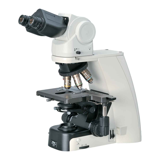
- Page 1 M568 E 11.8.NF.1 (1/2) *M568EN01* Upright Microscope Instruction Manual...
-
Page 3: Introduction
Introduction Thank you for purchasing a Nikon product. This instruction manual is written for users of the Nikon ECLIPSE Ci-S and Ci-L microscopes. To ensure correct usage, read this manual carefully before operating this product. ● No part of this manual may be reproduced or transmitted in any form without prior written permission from Nikon. -
Page 4: Contents Of The Manual
Introduction Contents of the Manual The manual for ECLIPSE Ci-S/Ci-L consists of the following contents. There is also a "Bright-field Microscopy Quick Guide", provided as a spearate document. ◆ This manual: Instructions Safety Precautions Microscopy Procedures Bright-field Microscopy Phase Contrast Microscopy... -
Page 5: Table Of Chapters
Table of Chapters Table of Chapters (See next page for the detailed contents.) Safety Precautions/ Introduction Notes on Handling the Product Contents of the Manual Symbols Used in This Manual Chapter 1-1 Microscopy Procedures Bright-field Microscopy Chapter 1-2 Microscopy Procedures Phase Contrast Microscopy Chapter 1-3 Microscopy Procedures... -
Page 6: Table Of Contents
Table of Contents Table of Contents Introduction ......................... i Contents of the Manual ....................ii Symbols Used in This Manual ..................ii Table of Chapters......................iii Safety Precautions......................vi WARNING and CAUTION Symbols used in This Manual..........vi Meaning of Symbols Used on the Product ..............vi WARNING ........................ - Page 7 Photomicroscopy....................54 16.2 Tips on Microscope Settings for Photomicroscopy .......... 55 Assembly....................57 ECLIPSE Ci-S/Ci-L System Configuration ..............57 Assembly for Bright-field Microscopy ..............58 Assembly for Phase Contrast Microscopy ..............62 Assembly for the Simple Polarizing Microscopy .............62 Assembly for Sensitive Polarization Microscopy.............63 Assembly for Epi-fluorescence Microscopy ............64...
-
Page 8: Safety Precautions
Precautions against heat This symbol is affixed to the part near the lamphouse of the ECLIPSE Ci-S to call your attention to the following: ● During and immediately after a period of illumination, the lamp and surrounding areas (including the lamphouse) are very hot. - Page 9 The light source used with the epi-fluorescence must be observed. attachment (HG Precentered Fiber Illuminator) Safety is a top design priority for Nikon products. requires special care during handling because of Safety is ensured as long as the user observes all its characteristics.
- Page 10 Safety Precautions WARNING Hazardous sample handling This product is intended primarily for microscopic observations and image capture of cells and tissue set on glass slides. Check to determine whether a sample is hazardous before handling. sample hazardous, handle it according to the standard procedure specified for your laboratory.
- Page 11 Lamp replacement precautions (when using ECLIPSE Ci-S) ● The main body weighs approximately 10 kg. When moving it, hold the main body by the grip ● To avoid burns, wait at least 30 minutes after...
-
Page 12: Notes On Handling The Product
Chapter 5, “2.1 Lens Cleaning”. point will damage this product. Never use undue force when turning the knob. Dirt on the lamp (ECLIPSE Ci-S) Protect the ports from dust and extraneous Never touch the lamp with bare hands. Dirt or... -
Page 13: Microscopy Procedures
Microscopy Procedures Bright-field Microscopy System Configuration and Controls This section explains an example system configuration and the controls required for bright-field microscopy using the ECLIPSE Ci-S/Ci-L. Chapter 1-1 Names of components are denoted in the following manner: [Eyepiece]. Diopter adjustment ring... -
Page 14: Bright-Field Microscopy Procedure
Chapter 1 Microscopy Procedures Bright-Field Microscopy Procedure Turn on the power. Lower condenser slightly from uppermost position. Fully open field aperture diaphragms. Chapter 1-1 Bring the 10x objective into the optical path. Bring specimen into optical path. Focus on specimen. 4 10 Adjust diopter. - Page 15 Chapter 1 Microscopy Procedures Lower the condenser slightly from the uppermost position. Turn the condenser focus knob until the condenser is positioned at the upper limit (where it clicks to a stop), and then lower it a little. Chapter 1-1 N D 4 N OU T Lower the condenser from upper limit...
- Page 16 Chapter 1 Microscopy Procedures Rotate the stage knob to move the stage and bring the target into the optical path. (So that the sample sealed under the cover glass will be lighted.) 0.8 0.6 0.4 0.2 Chapter 1-1 POWE R Bringing the Target into the Optical Path Focus on the specimen.
- Page 17 Chapter 1 Microscopy Procedures Notes on controlling the focus knobs Avoid the following action, which can cause equipment malfunction. 0.8 0.6 0.4 0.2 • Rotating the right and left focus knobs in opposite directions. • Rotating the coarse focus knob past the limit. POWER Chapter 1-1 Don't rotate the knobs in opposite directions!
- Page 18 Chapter 1 Microscopy Procedures Focus and center the condenser. (See Chapter 2, “5 Focusing and Centering the Condenser” for details) Look into the eyepiece with the field diaphragm stopped down to the minimum. Focus on the field diaphragm image using the condenser focus knob, 0.8 0.6 0.6 0.4 0.4 0.2...
- Page 19 Chapter 1 Microscopy Procedures Microscopy operation Select the desired objective. Turn the nosepiece to bring the desired objective into the optical path. Swing-out condenser 1-100x Chapter 1-1 Mounting a 1-100x swing-out condenser on the Ci-L main body when using the 1x objective may result in uneven illumination around the field of view.
- Page 20 Chapter 1 Microscopy Procedures Adjust the field diaphragm Turn the field diaphragm dial to adjust the field diaphragm so that it almost circumscribes the field of view. Size of the field diaphragm Field diaphragm dial Normally, adjust the field diaphragm so that it almost circumscribes the field of view.
-
Page 21: Phase Contrast Microscopy
Phase Contrast Microscopy System Components and Controls This section explains an example system configuration and the controls required for phase contrast microscopy using the ECLIPSE Ci-S/Ci-L. Names of components are denoted in the following manner: [Phase contrast condenser]. Diopter adjustment ring... -
Page 22: Phase Contrast Microscopy Procedure
Chapter 1 Microscopy Procedures Phase Contrast Microscopy Procedure In this procedure, only step titles are shown for operations that are the same as those of bright-field microscopy. See “2.1 Bright-field Microscopy” for details. Turn on the power. Lower condenser slightly from uppermost position. - Page 23 Chapter 1 Microscopy Procedures Move the condenser turret to the [A: empty] position. Turn the condenser turret until the [A: empty] symbol comes to the front, and align the hole with the optical path. Aperture diaphragm of the condenser Positioning the condenser turret at positions other than [A: empty] deviates the aperture diaphragm A: empty from the optical path.
- Page 24 Chapter 1 Microscopy Procedures Microscopy operation (→See also: Chapter 2, Section 14 “Tips for Phase Contrast Microscopy”) Bring the Ph annular diaphragm (Ph1) in the condenser turret into the optical path. Turn the condenser turret until the [Ph1] symbol comes to the front.
- Page 25 Chapter 1 Microscopy Procedures Bring an arbitrary Ph objective into the optical path. Turn the nosepiece to bring the desired Ph objective into the optical path. When using an oil immersion type objective, apply immersion oil between the specimen and the objective. (→Chapter 2 “12 Oil Immersion”...
- Page 26 Chapter 1 Microscopy Procedures Adjust the field diaphragm. Turn the field diaphragm dial to adjust the field diaphragm so that it almost circumscribes the field of view. Field Size of the field diaphragm diaphragm Normally, adjust the field diaphragm so that it dial almost circumscribes the field of view.
-
Page 27: Simple Polarizing Microscopy
System Configuration and Controls This section explains an example system configuration and the controls required for simple polarizing microscopy using the ECLIPSE Ci-S/Ci-L. Names of components are denoted in the following manner: [Polarizer unit for simple polarization]. Diopter adjustment ring... -
Page 28: Simple Polarizing Microscopy Procedure
Chapter 1 Microscopy Procedures Simple Polarizing Microscopy Procedure In this procedure, only step titles are shown for operations that are the same as those of bright-field microscopy. See “2.1 Bright-field Microscopy” for details. Turn on the power. Lower condenser slightly from uppermost position. - Page 29 Chapter 1 Microscopy Procedures Place a specimen on the stage, and move the stage to bring the target into view. Remove the analyzer and the polarizer from the optical path. Pull out the analyzer IN/OUT knob from the intermediate tube with simple analyzer to remove the analyzer from the optical path.
- Page 30 Chapter 1 Microscopy Procedures Microscopy operation Bring a portion of the specimen where there is no sample into the optical path. Rotate the stage knob to move the specimen and bring a portion where there is no sample under the cover glass into the optical path.
- Page 31 Chapter 1 Microscopy Procedures Adjust the orientation of the analyzer and the polarizer. Fully open the aperture diaphragm. Pull out one eyepiece from the tube. Look into the eyepiece sleeve and rotate the whole polarizer unit until you can identify a dark cross. (You will see black stripes that change shape as you rotate the polarizer unit.) Tighten the fixing screw of the polarizer unit to fix the polarizer.
- Page 32 Chapter 1 Microscopy Procedures View the specimen. Rotate the stage knob to move the target. If the target is not in focus, use the focus knob to adjust the focus. Strict polarizing microscopy If you need a retardation measurement or stricter polarizing observation, use a dedicated polarizing microscope.
-
Page 33: Sensitive Tint Plate Microscopy
System Configuration and Controls This section explains an example system configuration and the controls required for sensitive polarization microscopy using the ECLIPSE Ci-S/Ci-L. Names of components are denoted in the following manner: [Polarizer unit for first-order red compensation]. Diopter adjustment ring... -
Page 34: Sensitive Tint Plate Microscopy Procedure
Chapter 1 Microscopy Procedures Sensitive Tint Plate Microscopy Procedure In this procedure, only step titles are shown for operations that are the same as those of bright-field microscopy. See “2.1 Bright-field Microscopy” for details. Turn on the power. Lower condenser slightly from uppermost position. - Page 35 Chapter 1 Microscopy Procedures Place a specimen on the stage, and move the stage to bring the target into view. Remove the analyzer and the polarizer from the optical path. Pull out the analyzer IN/OUT knob from the sensitive tint plate analyzer unit to remove the analyzer from the optical path.
- Page 36 Chapter 1 Microscopy Procedures Microscopy operation Bring a portion of the specimen where there is no sample into the optical path. Rotate the stage knob to move the specimen and bring a portion where there is no sample under the cover glass into the optical path.
- Page 37 Chapter 1 Microscopy Procedures Adjust the orientation of the analyzer and the polarizer. Fully open the aperture diaphragm. Pull out one eyepiece from the tube. Rotate the lambda plate rotation lever (which makes the upper polarizer move around the pivot) to remove the lambda plate from the optical path.
- Page 38 Chapter 1 Microscopy Procedures View the specimen. Swing out the lambda plate from the optical path. (The field of view gets darker.) Rotate the stage knob to move the target. If the target is not in focus, use the focus knob to adjust the focus. (The specimen looks brighter in the dark field of view.) Bring the lambda plate back into the optical path.
-
Page 39: Epi-Fluorescence Microscopy
Microscopy Procedures Epi-fluorescence Microscopy System Configuration and Controls This section explains an example system configuration and the controls required for epi-fluorescence microscopy using the ECLIPSE Ci-S/Ci-L. Names of components are denoted in the following manner: [CI-FL epi-fluorescence attachment]. Diopter adjustment ring... -
Page 40: Epi-Fluorescence Microscopy Procedure
Chapter 1 Microscopy Procedures Epi-fluorescence Microscopy Procedure WARNING The light source used with the epi-fluorescence attachment (mercury lamp) requires special care during handling because of its characteristics. Make sure you are familiar with and adhere to all warnings and cautions described at the beginning of this instruction manual. - Page 41 Chapter 1 Microscopy Procedures Close the shutter and block the illumination path. Set the shutter open/close lever of the epi-fluorescence Filter cube attachment to position “C” to close the shutter and block switching knob the optical path. Shutter of the epi-fluorescence attachment CUBE The shutter blocks illumination.
- Page 42 When using an oil immersion type objective, apply immersion oil between the specimen and the objective. (→Chapter 2 “12 Oil Immersion” for details) Non-fluorescent immersion oil Use Nikon designated non-fluorescent immersion oil. Focus on the specimen. Look into the eyepiece, and adjust the brightness of the field of view with the ND filter of the epi-fluorescence attachment.
- Page 43 Diascopic image in fluorescence observation For fluorescence observations, turn off the microscope power switch to make the diascopic image disappear. Bright ambient lights will make it difficult to view the image. Nikon recommends keeping the room dark during fluorescence observations.
- Page 44 Chapter 1 Microscopy Procedures Chapter 1-5...
-
Page 45: Individual Operations
Individual Operations Adjusting the Brightness of a Diascopic Image The brightness of a diascopic image can be adjusted by changing the voltage of the lamp with the dia-illumination brightness control knob or by removing/inserting ND filters from or into the optical path. Adjustment with the Dia-illumination Brightness Control Knob Turning the dia-illumination brightness control knob changes the voltage of the lamp/LED to change the brightness of the... -
Page 46: Removing An Ncb Filter For A Brighter Image (Ci-S)
Chapter 2 Individual Operations Removing an NCB filter for a brighter image (Ci-S) Ci-S has an integrated NCB filter (NCB 11) to improve the color reproduction. If the image still looks dark even after all ND filters are removed from the optical path, removing this NCB filter can make the image brighter. -
Page 47: Focusing On The Specimen (Vertical Stage Movement)
Chapter 2 Individual Operations Focusing on the Specimen (Vertical Stage Movement) Note on controlling the focus knobs Avoid the following actions, which can cause equipment malfunction. 0.8 0.6 0.4 0.2 • Rotating the right and left focus knobs in opposite directions. •... -
Page 48: Focus Knob Rotation And Stage Movement
Chapter 2 Individual Operations Focus Knob Rotation and Stage Movement Both the coarse focus knob and the fine focus knob are located on both right and left sides on the microscope. The table below shows the relationship of the focus knobs' rotation with the stage movement. -
Page 49: Adjusting The Rotating Torque Of The Coarse Focus Knob
Chapter 2 Individual Operations Adjusting the Rotating Torque of the Coarse Focus Knob Adjust the rotation torque of the coarse focus knob (rotation resistance) by turning the torque adjustment knob (TORQUE) located at the base of the coarse focus knob. If the torque is set too low, the stage may descend under its own weight. -
Page 50: Position Exchange Of The Fine Focus Knob
Chapter 2 Individual Operations Position Exchange of the Fine Focus Knob Among left and right fine focus knobs, one is flat and another is convex. Both fine focus knobs are attached to the coarse focus 0.8 0.6 0.4 0.2 knobs using magnet, so you can detach the left and right knobs from the coarse focus knobs and swap them. -
Page 51: Bringing The Specimen Into The Optical Path (Horizontal Stage Movement)
Chapter 2 Individual Operations Bringing the specimen into the optical path (Horizontal Stage Movement) Note on moving the stage Avoid the following action, which can cause equipment malfunction. • Moving the stage to the right and left by holding the top surface of the stage directly. -
Page 52: Adjusting The Diopter
Chapter 2 Individual Operations Adjusting the Diopter The diopter adjustment ring on an eyepiece can be adjusted to match the eyesight of your right and left eyes. A properly adjusted diopter compensates for differences in visual acuity between the right and left eyes of a person, making binocular observation easier. -
Page 53: Adjusting Aperture Diaphragm
Chapter 2 Individual Operations Adjusting aperture diaphragm Adjust the condenser position so that the light passing through the condenser forms an image at the correct position (center of the optical path) on the surface of the specimen. Follow Steps 1 through 6 in Chapter 1 “1.2 Bright-field Microscopy”... -
Page 54: Adjusting The Aperture Diaphragm
The scale on the condenser indicates the numerical aperture. Plan 40X Chapter 2 The index on the aperture diaphragm lever should be aligned with 40x / 0.75 Nikon JAPAN Plan 40x the scale line that corresponds to 70 to 80% of the numerical 40x / 0.75 / -WD / -WD aperture of the objective. -
Page 55: Selecting A Condenser
Chapter 2 Individual Operations Selecting a Condenser Select a condenser optimal for the magnification of the objective and the microscopy procedure. Selecting the Magnification of the Objective and Condenser Condenser ( : Optimum, ○: Suitable, ×: Not suitable) Slide achro Achromat Swing-out Objective's... -
Page 56: Switching The Optical Path Of The Tube
Chapter 2 Individual Operations Switching the Optical Path of the Tube Light Distribution With the ergonomic binocular tube or trinocular eyepiece tube, the optical path switching lever allows distribution of light to the binocular section and camera port. Optical path switching lever Switching the Optical Path of the Tube... -
Page 57: Adjusting The Binocular Section
Chapter 2 Individual Operations Adjusting the Binocular Section Adjusting with the Binocular Section of the Tube 10.1 The ergonomic tube makes it possible to tilt and extend the binocular section. Adjust the position of the binocular section for most comfortable viewing. Adjusting the binocular section Using the Eyelevel Riser 10.2... -
Page 58: Oil Immersion
After use, thoroughly wipe off all oil, and make sure that no oil remains on the tips of other objectives. Additionally, carefully wipe off the oil from the condenser. Use petroleum benzine to wipe off the immersion oil. For optimum results, Nikon recommends cleaning with absolute alcohol (ethyl or methyl alcohol) after cleaning with petroleum benzine. -
Page 59: Water Immersion
Chapter 2 Individual Operations Water Immersion An objective with a “WI” or “W” marking is a water-immersion objective. Such an objective is used with immersion water (distilled water or physiological saline) applied between the specimen and the tip of the objective. Microscopy procedures are the same as for oil-immersion objectives. - Page 60 Chapter 2 Individual Operations Using the GIF filter The GIF filter (green interference filter) improves the contrast when placed in the optical path. The filter should be installed on the field lens, or placed inside or on top of the filter cassette holder. Note, however, that it may cause ghosting when mounted inside the filter cassette holder.
- Page 61 Chapter 2 Individual Operations To switch to phase contrast microscopy ● Close the shutter for the epi-fluorescence attachment and block the excitation light from the epi-fluorescence attachment. ● Turn the filter cube switching knob and move the position without a filter cube into the optical path. ●...
-
Page 62: Tips For Epi-Fluorescence Microscopy
Chapter 2 Individual Operations Tips for Epi-fluorescence Microscopy WARNING The light source used with the epi-fluorescence attachment (mercury lamp) requires special care during handling because of its characteristics. Make sure you are familiar with and adhere to all warnings and cautions described at the beginning of this instruction manual. -
Page 63: Switching Excitation Methods
Chapter 2 Individual Operations Light Reduction by Combined ND Filters of the Epi-fluorescence Attachment Brightness ND16 ○ ○ 1/16 ○ 1/32 ○ ○ 1/64 ○ ○ 1/128 ○ ○ 1/512 ○ ○ ○ (-: Removed from the optical path, ○: Placed into the optical path) Improving the S/N ratio (shielding tube) To improve the signal to noise ratio (SNR) during epi-fluorescence observations solely using epi-fluorescence microscopy, we recommend removing the condenser and using the shielding tube provided with the epi-fluorescence... -
Page 64: Selecting Filters
Chapter 2 Individual Operations Filter Cube Motion Restricting Lever Functions Lever position Filter cube switching Position A Locked (push in by two (filter cubes cannot be switched) notches) CUBE Switching between positions 1 and 2, or Position B between positions 3 and 4 only. (push in by one (The position at which the lever is pushed in notch) - Page 65 Chapter 2 Individual Operations EX Filter Bandwidth and Fluorescent Image Narrow EX filter bandwidth Wide Brightness of Dark Bright fluorescent image Generation of High autofluorescence Degree of color fading High Barrier filter (BA filter) Barrier filters allow only fluorescent light emitted by the specimen to pass, blocking excitation light. This allows the fluorescent image to be viewed without excess illumination (dark background).
-
Page 66: Capturing Images
Chapter 2 Individual Operations Capturing Images When the DS-U3 or DS-L3 DS Camera Control Unit is connected Camera head to the microscope, you can use the Capture button on the base of the microscope to capture digital images with ease. When using a tube that allows for light distribution to the binocular section and the camera port, images can also be captured while in an observation posture from the binocular... -
Page 67: Tips On Microscope Settings For Photomicroscopy
Even if the overall magnification is the same on the monitor, the combination of objective and camera zoom can result in significant variations in exposure time. Nikon recommends increasing the magnification of the objective rather than of the zoom. (Generally, the numerical aperture of the objective increases with magnification. The larger... - Page 68 Chapter 2 Individual Operations ■ Adjusting the excitation light Excessively bright excitation light will accelerate the decoloration of the specimen, making it more difficult to acquire suitable fluorescent images. Insert ND filters into the optical path to adjust the brightness. ■...
-
Page 69: Assembly
Assembly ECLIPSE Ci-S/Ci-L System Configuration ENG mount camera C mount camera photomicrography device TV adapter Centering telescope CFI eyepiece Eyelevel riser Camera head Analyzer unit Binocular tube Trinocular tube Ergonomic tube DSC port Filter cube CI-FL epi-fluorescence attachment Spacer for... -
Page 70: Assembly For Bright-Field Microscopy
WARNING If the indicated voltage and the supplied voltage differ, do not attempt to use the microscope. Contact DS C your nearest Nikon representative for advice. Checking the input voltage Attaching the stage Stage clamp screw Turn the coarse focus knob to remove the cushioning material from the substage section. - Page 71 Chapter 3 Assembly Attaching the condenser Turn the coarse focus knob until the elevating Condenser focus knob section is brought to the upper limit. Turn the condenser focus knob until the condenser holder reaches the bottom. Insert the condenser, adjust it to face the front, then secure it in place with the tool.
-
Page 72: Attaching The Nosepiece
Chapter 3 Assembly Attaching eyepieces Protrusion Notch Make sure the notch on the eyepiece side and the protrusion of the eyepiece sleeve are aligned, then insert the eyepieces. Notch on eyepiece Eyepiece has a notch to prevent rotation. When attaching, match the notch with the protrusion on the eyepiece sleeve. -
Page 73: Connecting The Power Cord
Chapter 3 Assembly Connecting the power cord WARNING Be sure to use the specified power cord. Use of other power cords may result in malfunction or fire. This product is classified as having Class I protection against electric shock. Make sure this product is connected to an appropriate protective earth terminal. -
Page 74: Assembly For Phase Contrast Microscopy
Chapter 3 Assembly Assembly for Phase Contrast Microscopy Follow the procedure described in Section 2 “Assembly for Bright-field Microscopy” to perform assembly. Note the following: ■ Attaching a condenser for phase contrast microscopy Use a condenser for the phase contrast microscopy in the step 3, “Attaching the condenser.” The procedure is the same. -
Page 75: Assembly For Sensitive Polarization Microscopy
Chapter 3 Assembly Assembly for Sensitive Polarization Microscopy Follow the procedure described in Section 2 “Assembly for Bright-field Microscopy” to perform assembly. Note the following: ■ Attaching an analyzer tube for first-order red compensation Attach an analyzer tube for first-order red compensation to the microscope arm prior to the step 4, “Attaching the tube.”... -
Page 76: Assembly For Epi-Fluorescence Microscopy
Chapter 3 Assembly Assembly for Epi-fluorescence Microscopy Follow the procedure described in Section 2 “Assembly for Bright-field Microscopy” to perform assembly. Note the following: ■ Attaching the epi-fluorescence attachment Attach the epi-fluorescence attachment to the microscope arm prior to the step 4, “Attaching the tube.” Place epi-fluorescence attachment... - Page 77 Chapter 3 Assembly ●Removing/attaching the internal spacer● Filter cube Place the filter cube on a work table with the excitation filter facing up. Unscrew the ring retaining the excitation filter. (Be careful to avoid dropping the filter.) Remove the spacer inside the removed ring. Remove or reverse the spacer as appropriate for the particular filter cube type before its insertion.
-
Page 78: Attaching A Camera
Chapter 3 Assembly Attaching a Camera ■ When attaching a camera head to the ergonomic tube Screw the camera head into the C mount on the DSC port. Camera head Remove the rear cover of the ergonomic tube and C-mount insert the DSC port. -
Page 79: Troubleshooting
If you detect problems that are not listed below or the problem still persists after measures are taken, turn off the device and contact your nearest Nikon representative. Optical System and Operation... - Page 80 Chapter 4 Troubleshooting Problem Cause Measure Check and clean by following the procedure in “If dirt or dust does not turn by rotating the Lens and specimen are dirty or dusty. eyepiece” in “When looking into the eyepiece, dirty or dusty field of view”. Open it to proper size.
- Page 81 Tip of the objectives without stopper can not protection of the objective is pushed in. be rotated. Do not use force to draw the stopper. Contact your nearest Nikon representative. Screw the objective all the way in. An objective is attached incorrectly.
- Page 82 Chapter 4 Troubleshooting Problem Cause Measure Attach it correctly and rotate to the click stop The nosepiece is not attached correctly, or position. has not been fully rotated to the click stop (→Chapter 3, “2 Assembly for Bright-field position. Microscopy ― 6 Attaching the nosepiece”) One side of the field of Position the specimen in place on the stage.
-
Page 83: Epi-Fluorescence Microscopy
Chapter 4 Troubleshooting Epi-fluorescence Microscopy Problem Cause Measure Lack of visibility around periphery of field of view. Push the cube in to the limit. Illumination is uneven The filter cube is misaligned. (→Chapter 3, “6 Assembly for Epi-fluorescence across the field of view. Microscopy ―... -
Page 84: Phase Contrast Microscopy
Chapter 4 Troubleshooting Phase Contrast Microscopy Problem Cause Measure Adjust so that they match. The Ph annular diaphragm of the condenser does not match the phase plate (→Chapter 1, “2.2 Phase Contrast Microscopy image of the objective. Procedure ― 12 Center the Ph annular diaphragm”) Put the Ph annular diaphragm with the same Ph code as the objective into the optical path. -
Page 85: Electrical Requirements
The mercury lamp burns (→Check your illuminator's manual) The lamp type is incorrect. out soon after it is turned If the lamp burns out immediately after the Lamp is at end of its life. replacement, please contact your nearest Nikon representative. - Page 86 Chapter 4 Troubleshooting Chapter 4...
-
Page 87: Maintenance And Storage
Maintenance and Storage Replacing the Lamp (for Ci-S) CAUTION • Beware of burns: Wait until the lamp and nearby parts have cooled before replacing the lamp. • Beware of electrical shock: Turn off the power switch and unplug the power cord from the wall outlet. •... -
Page 88: Cleaning
Chapter 5 Maintenance and Storage Cleaning Follow these procedures when cleaning or decontaminating lenses or other parts. ■ Tools used for cleaning ・Blower ・Soft brush ・Soft cotton cloth, lens tissue, or gauze etc. ・Absolute alcohol (ethyl or methyl alcohol), medicinal alcohol ・Petroleum benzine (used only for cleaning immersion oil) CAUTION •... -
Page 89: Cleaning The Immersion Oil
• Switch off the microscope (press the switch to the “O” position) and wait for the lamphouse to cool before covering this product with a cover. Regular Inspections (Charged) To maintain the performance of this product, Nikon recommends periodic inspections (chargeable service). Contact your nearest Nikon representative for details. Chapter 5... - Page 90 Chapter 5 Maintenance and Storage Chapter 5...
-
Page 91: Specifications And Safety Standards
■ Intended user It is intended for the medical professional and those who work on experimentations in the field of pathology and cytology. Performance Properties ■ Nikon Microscope ECLIPSE Ci-S Model ECLIPSE Ci-S Optical system Infinity-corrected CF optical system Objective... - Page 92 PSE approved detachable power cord set, 3 conductor grounding (3 conductor grounding Type VCTF 3 x 0.75 mm , 3 m long maximum, rated at 125 VAC minimum) ■ CI-FL Epi-fluorescence Attachment for Nikon Microscope Model CI-FL epi-fluorescence attachment Optical system Infinity-corrected CF optical system...
-
Page 93: Physical Properties
External dimensions and External dimensions: 223 (W) x 331.5 (H) x 331 (D) mm weight (Main body only) (excluding projections) Weight: Approx. 10 kg CI-FL Epi-fluorescence Attachment for Nikon Microscope ■ Model CI-FL epi-fluorescence attachment Operating conditions Temperature: 0°C to +40°C Humidity: 60% RH max. - Page 94 Chapter 6 Specifications and Safety Standards Chapter 6...