Table of Contents
Advertisement
Quick Links
Advertisement
Table of Contents

Related Manuals for Honeywell FMC2000


Summary of Contents for Honeywell FMC2000
- Page 1 User Guide FMC2000...
-
Page 2: Fcc Information
At the end of its life, this product must undergo separate collection and recycling from general or household waste. Please use the return and collection system available in your country for the disposal of this product. © Copyright 2014 Honeywell Analytics... -
Page 3: Table Of Contents
Status LEDs .............. 17 Display ..............17 Keypad ..............18 Alarms ..............18 Preparing The FMC2000 For Data Storage ....19 Operating The FMC2000 ..........22 Turning The FMC2000 On ........22 Turning The FMC2000 Off ........24 Display Information ............25 Display Icons ............ - Page 4 FMC2000 User’s Guide 11.5.3 MeshGuard Router ..........36 Configuration ..............37 General Settings Menu ..........38 13.1 Basic Settings ............39 13.2 Date Format .............. 40 13.3 Date ................40 13.4 Time Format ............. 41 13.5 Time ................41 13.6 Language ..............
- Page 5 FMC2000 User’s Guide 15.9 TWA ................. 52 15.10 Full Scale .............. 52 15.11 Drift ..............52 15.12 Reset LEL ............. 52 Relay Settings ............... 53 16.1 Relay Ratings (Resistive) ......... 53 16.2 Type ................54 16.3 DON ................. 54 16.4 DOF ................
- Page 6 Appendix E: Connecting to a Light/Alarm Bar .... 94 Appendix F: Formatting An SD Card For FAT32 ..95 31.1 Formatting An SD card ..........95 Appendix G: ModBus Protocol For The FMC2000 ... 101 32.1 Overview ..............101 32.2 Communications Settings ........
- Page 7 FMC2000 User’s Guide Read Before Operating This manual must be carefully read by all individuals who have or will have the responsibility of using, maintaining, or servicing this product. The product will perform as designed only if it is used, maintained, and serviced in accordance with the manufacturer’s...
-
Page 8: Special Notes
FAT32, it must be formatted before use. See Appendix C. The FMC2000 must be properly grounded. Follow local electrical codes when installing and using. Connect a ground wire to the bolt inside the front panel to ground the chassis:... -
Page 9: Warnings
FMC2000 User’s Guide WARNINGS Use only in non-hazardous locations. For safety reasons, this equipment must be operated and serviced by qualified personnel only. Read and understand instruction manual completely before operating or servicing. AVERTISSEMENT Utiliser uniquement en zone non-dangereuse. Pour des raisons de sécurité, cet équipment doit être utilisé, entretenu et réparé... -
Page 10: Standard Contents
Installation guide/quick-start guide • CD-ROM with User’s Guide, Quick-Start Guide, and related materials 3 General Information The FMC2000 Multi Controller works with provided by Honeywell Analytics Mesh wireless detectors, such as MeshGuard, RAETag, RAEWATCH, for various safety applications. Key Features •... -
Page 11: Physical Description
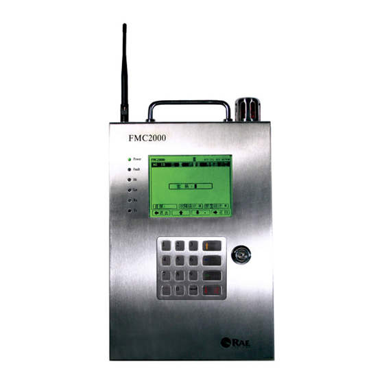
FMC2000 User’s Guide 4 Physical Description The main components of theFMC2000 include: • 16 keys for programming and reviewing settings • LCD display with back light for direct readout and readout from MeshGuard monitors • Buzzer and red light for alarm signaling whenever exposures exceed preset limits •... -
Page 12: Rear View And Side View Of Enclosure
Mounting Captures Mounting the FMC2000 The FMC2000 is designed to be wall-mounted and has four keyhole-type captures on its back, allowing for attachment to four mating studs extending from a bracket that is designed to be pre- installed on a wall. - Page 13 FMC2000 User’s Guide 2. Drill the holes and screw the bracket to the wall. 3. Support the weight of the FMC2000 and align the large ends of the keyhole-shaped mounting captures on the rear of the enclosure with the four studs protruding from the bracket.
-
Page 14: Drilling Chart
FMC2000. Drilling Chart When mounting the FMC2000 on a wall, make sure to use heavy- duty steel screws spaced as indicated below. Note: All dimensions are in millimeters. -
Page 15: Specifications
FMC2000 User’s Guide 5 Specifications Size 9.5" W x 15.7" H x 3.7" D (24cm x 40cm x 9.3cm) 14.3 lbs (6.5 kg), excluding mounting plate Weight 5.7″ (15cm) 320x240 Black/White graphic LCD Display LCD with backlight 95dB @ 30cm (12″) -
Page 16: Charging The Internal Backup Battery
AC power source is interrupted. It is fully charged after 6 to 8 hours of operation. The FMC2000 can run for up to 15 hours on the backup battery. Clock Battery An internal clock battery is mounted on the top printed circuit board. - Page 17 Note: The SD card inside the FMC2000 should only be used for FMC2000 data recording. Do not save other files to the SD card. In addition, do not use one SD card for more than one FMC2000 or exchange it from one FMC2000 to another.
-
Page 18: User Interface
FMC2000 User’s Guide User Interface The instrument’s user interface consists of the display, status LEDs, an alarm buzzer, an alarm light, and 16 keys. Status LEDs Display Alarm Light Alarm Buzzer Keypad... -
Page 19: Status Leds
FMC2000 User’s Guide Status LEDs The status LEDs provide the following basic visual information: Information Power Glows green when the FMC2000 is on Fault Glows orange when problem is encountered Glows red during High Alarm Glows red during Low Alarm... -
Page 20: Keypad
Keypad The keypad is used to navigate the menus and parameters in the FMC2000. Many of the keys perform dual functions, and the four large keys arranged vertically along the right side correspond to the “soft key” icons arranged along the bottom of the display. -
Page 21: Preparing The Fmc2000 For Data Storage
FMC2000 User’s Guide Preparing The FMC2000 For Data Storage Before operating the FMC2000, make sure it has an SD card in the memory slot. This is necessary for storing datalog information. 1. Unlock the FMC2000. 2. Open the door. The SD card slot is on the main PC board as shown:... - Page 22 FMC2000 User’s Guide To place the FMC2000 in Standby Mode and replace the SD card: 1. Hold down the “2” key until you see the display message “Standby...” The screen goes blank. 2. Release the “2” key. 3. Unlock and open the front panel.
- Page 23 Press here The FMC2000 cannot write data to a locked SD card. If the SD card is locked, remove it and unlock it by moving the lock tab;...
-
Page 24: Operating The Fmc2000
Turning The FMC2000 On 1. Connect the FMC2000 to a source of AC power. 2. With the FMC2000 turned off, unlock the front panel with the key, and flip the small toggle switch located next to the SD card. - Page 25 Honeywell Analytics Technical Service. The FMC2000 performs self-tests on its LCD, LEDs, and buzzer. It also initializes connection with a wireless network or Ethernet interconnection (if it is configured for Ethernet networking). After 30 seconds, the display shows the monitoring screen, indicating that it is monitoring the system.
-
Page 26: Turning The Fmc2000 Off
3. Check that the LEDs are no longer glowing. This indicates the FMC2000 is off. Note: After starting or shutting down the FMC2000, we recommend locking the case again to keep dust out, and to prevent tampering by unauthorized personnel. -
Page 27: Display Information
FMC2000 User’s Guide 9 Display Information If remote monitors are connected and sending data to the Controller, each monitor’s data is shown in a row with an identification number, radio ID, Station name, sensor value (reading), sensor type, and status (OK checked). -
Page 28: Display Icons
FMC2000 User’s Guide Display Icons Icons show active functions and alert you to conditions. The icons used by the FMC2000 include: Icon Function Datalogging is active (Flashing icon) SD card is missing; datalogging stopped Detector sensor error Detector sensor okay... - Page 29 FMC2000 User’s Guide Radio enabled (Host) Radio disabled FMC2000 is running on AC power FMC2000 is running on battery power Locks to the selected sensor before checking details (stops automatic updating) Unlocks the selected sensor (resumes automatic updating) FMC2000 alarm is silenced Monitor missing (shows the number of monitors missing from the network, such as “01 OFF,”...
-
Page 30: Navigation
In addition to labeled functions, most keys have more than one role. For example, pressing the “1” key while the FMC2000 is monitoring enters the main menus, while pressing the “0” key tells it to perform a system test (this requires a 4-digit password; the... -
Page 31: Normal Operation Mode Controls
FMC2000 User’s Guide 11 Normal Operation Mode Controls From the normal operation screen, you can use the “soft keys” to do the following: • Radio Silent. Turn the radio on or off (enable/disable). • Reset. Reset the system. • Alarm Silent. Silence the alarm. -
Page 32: Silence Alarm
FMC2000 User’s Guide 11.3 Silence Alarm If the system is in alarm, you can silence the local alarm buzzer. Press the down-arrow/alarm-silence button. The local alarm buzzer is silenced, but the red alarm light continues to flash and the relay continues to act in the state of alarm. If the relay setting is set to latch, a pop-up screen asks if you want to disable the relay. -
Page 33: Check (Alarm Details)
5. Press Enter. This exits the alarm check and returns to the normal operation screen. Note: If you do not want to clear the alarm, skip steps 4 and 5, and press the left-arrow key. The FMC2000 returns to normal monitoring. - Page 34 FMC2000 User’s Guide From the Normal Operation Mode main screen, you can enter two different menus, the Main Menu and the Detail Menu. Pressing the keys shown navigates through the menus and submenus. The General Settings, Datalog, and Communication menus are detailed in the Configuration section, starting on page 37.
-
Page 35: Monitoring
11.5.1 Detail Info You can quickly access a list of the last 10 alarms and the last 10 faults recorded in the FMC2000. 1. Press the right arrow (Check) to select 1st Alarm/Faults/Alarms. 2. Press the right arrow (Check) to highlight Faults or Alarms. -
Page 36: Meshguard Ec Or Lel
FMC2000 User’s Guide 11.5.2 MeshGuard EC Or LEL 1. Press the Lock button to stop auto-scrolling. The monitor labeled No. 1 (top of the list) is highlighted. The Lock icon appears at the top of the screen. 2. Press the up or down arrow key to select a remote monitor from the list. - Page 37 FMC2000 User’s Guide The information in the Detail window for a MeshGuard EC or LEL consists of the following: • Location • Serial Number • Modem ID • Detector Name • Detector Battery Capacity • Sensor • Alarms • Last Alarm (proceeds to second page) •...
-
Page 38: Meshguard Router
FMC2000 User’s Guide 11.5.3 MeshGuard Router The information in the Detail window is less extensive when a MeshGuard Router’s data is displayed. It consists of the following: • Location • Serial Number • Modem ID • Detector Name • Detector Battery Capacity •... -
Page 39: Configuration
FMC2000 User’s Guide 12 Configuration When the controller is in Normal Operation Mode, press the “MENU” key to enter the Configuration menu. You must provide a 4-digit password (the default value is 1234), followed by pressing Enter. The display now looks like this:... -
Page 40: General Settings Menu
FMC2000 User’s Guide Press the up or down arrow keys to move from one menu to the next in sequence. The bounding box surrounds each icon in sequence, acting to highlight it, and the text below matches the icon. Press Exit or Back to exit from the Configuration screen and return to monitoring. -
Page 41: Basic Settings
13.1 Basic Settings This menu provides submenus for setting parameters that do not often require changes, but are basic to the FMC2000’s operation and datalogging. In addition, information about the FMC2000 is included, such as serial number and firmware version. -
Page 42: Date Format
FMC2000 User’s Guide 13.2 Date Format The Date Format allows you to change the way the month, year, and date are indicated. Options include: Format Explanation mm/dd/yyyy Month, day, 4-digit year dd/mm/yyyy Day, month, 4-digit year yyyy/mm/dd 4-digit year, month, day... -
Page 43: Time Format
FMC2000 User’s Guide 13.4 Time Format The clock can be set to operate in 12-hour or 24-hour mode. 1. Press Enter to change the time format. 2. Press the up or down arrow to step between the format options (12-hour or 24-hour). - Page 44 FMC2000 User’s Guide 3. After you have changed the four digits for the time, press Enter to register the time. 4. AM or PM is highlighted by a blinking box. Change AM to PM (or vice versa) by pressing the up or down arrow.
-
Page 45: Language
FMC2000 User’s Guide 13.6 Language Different languages are supported by the FMC2000, depending on the firmware version. Scroll from English (the default) to other languages. 1. Press Enter to change the language. 2. Press the up or down arrow to step through the language options. -
Page 46: Instrument Location
FMC2000 User’s Guide 13.8 Instrument Location This tells the location of the FMC2000 controller. You can set this information in the FMC2000 and it is included in the datalog information on the SD card. 1. Press Enter to change the instrument’s location. -
Page 47: Advanced Settings
FMC2000 User’s Guide 14 Advanced Settings Under Advanced Settings, you can change/set passwords and activate the unit’s offline alarm. You must use an advanced (6- digit) password to enter. 1. Press Enter. 2. Input the 6-digit advanced password (the default is 123456). -
Page 48: Advanced Password
14.3 Online Monitors This setting tells the FMC2000 how many monitors the network includes. It sets the minimum number of monitors that the FMC2000 is in communication with. The FMC2000 always knows when monitors go off-line or are moved out of range of the network, and when the number of monitors in the network drops below the minimum set here, a Fault alarm is sounded. -
Page 49: Delete Monitors Configuration
14.4 Delete Monitors Configuration This allows you to delete the configuration of the monitors. This is important if you are using the FMC2000 with different sets of MeshGuard monitors. By deleting existing configurations, the FMC2000 has more memory space to devote to the new monitors. -
Page 50: Alarm Light
FMC2000 User’s Guide 14.8 Alarm Light This sets whether the alarm light on top of the FMC2000 glows when the system is in alarm. 1. Press the up or down arrow to select Enable or Disable. 2. Press Enter. 14.9 Backup Configuration This backs up the FMC2000’s configuration to the SD card. -
Page 51: Factory Reset
14.11 Factory Reset This performs a factory reset, which restores all settings in the FMC2000 to the original settings from the factory. If a factory reset is performed, then all settings you may have programmed are wiped clean and overwritten. -
Page 52: Modem Id
15.1 Modem ID (S) Select the ID of one of the remote monitor’s modems so that you can change its detector settings in the FMC2000. 1. Press Enter. 2. Press the up or down arrow to move through the list of IDs. -
Page 53: Sensor Type
FMC2000 User’s Guide 3. Press Back to return to the Wireless Detector Settings menu without saving your changes, or press Exit to return to the monitoring screen without saving your changes. 15.4 Sensor Type (R) This tells you the type of sensor in the remote monitor. -
Page 54: Twa
FMC2000 User’s Guide 15.9 TWA (R) This gives a readout of the TWA value. 15.10 Full Scale (R) N/A 15.11 Drift (R) N/A 15.12 Reset LEL (S) This only applies to a MeshGuard LEL. If the MeshGuard LEL goes over range, you can reset the MeshGuard LEL to normal. -
Page 55: Relay Settings
FMC2000 User’s Guide 16 Relay Settings Each of the five relays has a normally open (NO) and normally closed (NC) switch. The Number 1 relay is dedicated to controlling a Low Alarm state. The other four relays are dedicated to High Alarm states. -
Page 56: Type
FMC2000 User’s Guide delayed on or delayed off, plus logic can be programmed so that relays only open (or close) when specific multiple monitors go into alarm simultaneously (AND) or when one or more of a specific set of monitors goes into alarm. -
Page 57: Dof
FMC2000 User’s Guide 16.4 DOF Delay Off. This is the delay time for the relay switch turning off (returing to its pre-alarm state). 1. Press Enter. 2. Press number keys to enter a new Delay Off value (0 to 60 seconds). -
Page 58: Vote
FMC2000, it goes into alarm. 1. Press Enter. 2. With the first line highlighted, press the up or down arrow to select which one you want to edit. -
Page 59: Num
FMC2000 User’s Guide 16.7 Num Total number included in the logic group. This tells the number of monitors included in the logic group. If “ALL” has been selected, the number representing all of the monitors is shown, rather than an indication of “ALL.”... -
Page 60: Datalog Settings Menu
To step through the list of submenus: Press the up arrow or down arrow key. To select a submenu: Press Enter. 17.1 Datalog This shows you with a checkbox whether the FMC2000 is datalogging (storing data). You can manually start or stop the datalogging. 1. Press Enter to highlight the checkbox. -
Page 61: Log Interval
17.3 Log Method The FMC2000 can save log data either at the log interval you set or only when an alarm event takes place. If you select “Alarm,” then a log is only stored when there is an alarm event. This can save a great deal of space on the SD card used to store the data. -
Page 62: Sd Card Info
FMC2000 User’s Guide 17.4 SD Card Info This shows the status of the SD card, if one is installed. If one is installed, the checkbox next to “OK” is checked. If one is not installed, the checkbox next to “No Card” is checked. Status... -
Page 63: Communications Menu
FMC2000 User’s Guide 18 Communications Menu This menu sets the parameters for connection. This menu requires an advanced (6-digit) password for entry. • Wireless Modem • Ethernet Network • RS485 • Monitor MB Address Setting To enter: Press the Enter key. Input the 6-digit password. Press Enter again. -
Page 64: Wireless Modem
The FMC2000 sends a radio synchronization command to bind the detectors to the controller within the same network. When this is on, the monitors in a network synchronize with the FMC2000. Therefore, when a message is sent by a monitor to the... -
Page 65: Radio Panid
IMPORTANT! Make sure all monitors in the network have the same Pan ID number in order to communicate within the network. If you change the Pan ID number on the FMC2000, make sure you check the other Pan IDs. -
Page 66: Del Binding
• Auto Ping: 10 Seconds Ping NTW (network) sends a ping signal to all the units on the network one time. Auto Ping automatically sends a ping signal once every 10 seconds until pinging is turned off at the FMC2000. -
Page 67: Ethernet Network
FMC2000 User’s Guide 18.2 Ethernet Network The FMC2000 can be connected to a network via Ethernet. This requires using an Ethernet cable with an RJ-45 connector, plugged into the port on the upper circuit board. The other end can be plugged into a hub, router, or other access point to a network or to the Internet. -
Page 68: Protocol Select
FMC2000 User’s Guide overhead to the system, it is recommended that you disable TCP/IP if you are not using it. There are only two options, Enable and Disable. Change the setting in the following way: 1. Press Enter. 2. Press Up or Down to select Enable or Disable. -
Page 69: Server Ip
FMC2000 User’s Guide 18.2.3 Server IP Input the IP address of your system’s server that the FMC2000 is connecting to, if you know it. Check with your IT department for guidance on setting IP addresses for you system within a network. -
Page 70: Subnet Mask
FMC2000 User’s Guide If necessary, check with your IT department for guidance on setting a Client IP address to be used within a network. To set the Client IP address: 1. Press Enter 2. Press a digit (1 through 9). After each number it advances to next digit. -
Page 71: Re-Obtain Ip
A MAC (Media Access Control) address is an address used to represent hardware devices on an Ethernet network. Each MAC address is unique. An example of a MAC address is 00-13-20-80- 15-80. Note: You cannot change the FMC2000’s Client MAC address. -
Page 72: Baud Rate
(bps). For proper data transfer, the baud rate must be the same at the transmitting and receiving ends of a connection. Options for the FMC2000 are 4800, 9600, 19200 baud. The default value is 19200. -
Page 73: Client Id
ASCII, and vice versa. 1. Use the up and down arrows to select either RTU or ASCII. 2. Press Enter. Note: For detailed technical reference material covering the FMC2000’s ModBus implementation, see Appendix G, beginning on page 101. -
Page 74: Protocol
Dynamic: Links the Modbus output to the ID of the instrument communicating with the FMC2000 (for example, 15A8, etc.). Static: Links ModBus output to the unit number in the leftmost column of the main display (1, 2, 3, 4, etc.). -
Page 75: Diagnostic Menu
FMC2000 User’s Guide 19 Diagnostic Menu The Diagnostic menu consists of a Relay Diagnostic operation screen, where you can test the relays in the FMC2000. 19.1 Relay Output Diagnostic To access the relay tests: 1. Press Enter. 2. Input the 6-digit advanced password. - Page 76 FMC2000 User’s Guide In addition, you can hear the relay click, which tells you that the relay is changing state. 4. Exit and return to the main reading screen by pressing Exit, or go back to the previous screen by pressing Back.
-
Page 77: Transferring Data From The Sd Card
20 Transferring Data From The SD Card The data stored on the SD card (part number 550-0300-000) in the FMC2000 is in standard ASCII text format, making it easy to import into most spreadsheet and word-processing programs. In addition, it is in CSV (comma-separated value) form, so that it can ®... - Page 78 FMC2000 User’s Guide Once the SD card is in the adapter and connected to the computer, it should show up as an external device or a drive. 1. Double-click the My Computer icon on your desktop. When it opens, you should see a list of drives, including your C: drive, where most programs reside, and the external device holding the SD card.
-
Page 79: After Transferring Data From The Sd Card
(move the tab on the left side of the card to the “locked” position). This ensures that if it is put into a computer or FMC2000, data cannot be written to it. - Page 80 FMC2000 User’s Guide Another option is to erase the SD card. To erase the data, follow these steps: 1. Make sure the locking tab on the SD card is in the “unlocked” position. 2. Insert it into the computer or the adapter (and plug that into the computer).
-
Page 81: Maintenance
22.1 Battery Charging & Replacement A fully charged battery runs the FMC2000 for up to 15 hours continuously. The charging time is less than 8 hours for a fully discharged battery. If the 12-volt lead-acid battery is old and does not hold a charge, replace it with a new one, part number 500- 0132-000. -
Page 82: Special Servicing Note
FMC2000 User’s Guide 22.3 Special Servicing Note If the instrument needs to be serviced, contact either: The distributor from whom the instrument was purchased; they will return the instrument on your behalf. Honeywell Analytics Technical Service. -
Page 83: Troubleshooting
FMC2000 after the Discharged battery. main AC power is Defective battery. disconnected Solutions: Turn off the FMC2000, and turn it on again using its power switch. Make sure main power is connected and turned on. Charge or replace battery. - Page 84 FMC2000 User’s Guide Relay(s) not Reasons: Wiring to relay may be functioning incorrect. Relay settings may be incorrect. Relay may be damaged or defective. Solutions: Check wiring, including at alarm or other connected equipment. Check Relay Settings. Use continuity tester or...
-
Page 85: Technical Support
FMC2000 User’s Guide 24 Technical Support To contact the Honeywell Analytics Technical Support Team: Telephone +44 (0) 1202 645544 e-mail HAexpert@honeywell.com... -
Page 86: Honeywell Analytics Contacts
FMC2000 User’s Guide 25 Honeywell Analytics Contacts Europe, Middle East, Africa, India Life Safety Distribution AG Javastrasse 2 8604 Hegnau Switzerland Tel: +41 (0)44 943 4300 Fax: +41 (0)44 943 4398 India Tel: +91 124 4752700 Email: gasdetection@honeywell.com Americas Honeywell Analytics Inc. - Page 87 FMC2000 User’s Guide Technical Services EMEAI: HAexpert@honeywell.com US: ha.us.service@honeywell.com AP: ha.ap.service@honeywell.com...
-
Page 88: Appendix A: Wiring The Fmc2000
FMC2000 User’s Guide 26 Appendix A: Wiring The FMC2000 Follow local ordinances when wiring the FMC2000 for AC power. 26.1 DC Wiring 26.2 AC wiring... -
Page 89: External Alarms
FMC2000 User’s Guide 27 Appendix B: Wiring The FMC2000 To External Alarms The five relays are wired for NO (normally open) and NC (normally closed) operation. IMPORTANT! Read this before wiring a RAEPoint to control external customized loads. 1. Before wiring a RAEPoint to control external devices, consult the datasheet that applies to the RAEPoint’s relays:... -
Page 90: Wiring Blocks In The Fmc2000
FMC2000 User’s Guide 27.1 Wiring Blocks In The FMC2000 (The schematic below is included inside the FMC2000.) -
Page 91: Relay Electrical Drawing
FMC2000 User’s Guide Explanation of wiring blocks: 10V output provides 10 VDC @ 2A RS-485 data output Relays 2, 3, 4, and 5 are for High Alarm Relay 1 is for Low Alarm 27.2 Relay Electrical Drawing... -
Page 92: Checking Relay Continuity
FMC2000 User’s Guide 27.3 Checking Relay Continuity Each relay has a common terminal and a normally open (NO) and normally closed (NC) terminal. Use a continuity tester or voltmeter (set to measure resistance) to check the relay’s activity. 1. Enter the Relay Diagnostic menu. Press Enter, followed by the password (the default is 123456). -
Page 93: Appendix B: Wiring To External Alarms
Contact Honeywell Analytics Customer Support. 27.3.1 Power Supply Connections Although the connections are shown on the diagram, and there are connection points, the power supply should only be used for charging the backup battery and powering the FMC2000. -
Page 94: Dry Contact Operation
To remove a jumper, pull it straight up. 28 Appendix C: Connecting RS485 (Modbus) Follow standard Modbus procedures when connecting the FMC2000 via RS-485. Wires should be connected to points 16 and 17. Note: Configuration must be done in the menus of the FMC2000 for proper operation. -
Page 95: Appendix D: Connecting Ethernet
Use a pen or jeweler’s screwdriver to push the switch handles to the “RS485” position. 29 Appendix D: Connecting Ethernet Connecting the FMC2000 to a network via Ethernet requires plugging an Ethernet-compatible cable (typically, an RJ-45 connector on Cat-5 cable) into the Ethernet port on the upper PC board and then configuring the IP address, data type, etc. -
Page 96: Appendix E: Connecting To A Light/Alarm Bar
FMC2000 User’s Guide 30 Appendix E: Connecting to a Light/Alarm Bar The FMC2000 has a multi-pin connector on the bottom that is designed for connection with a provided by Honeywell Analytics FA-200 Light/Alarm Bar. The internal wires from the connector are prewired to the NO (Normally Open) connection points on the five relay wiring blocks. -
Page 97: Appendix F: Formatting An Sd Card For Fat32
For FAT32 SD cards typically come pre-formatted by the manufacturer, but for an SD card to operate properly in the FMC2000, it must be formatted for FAT32, a 32-bit file allocation system. If the card is formatted for FAT or FAT16 or unformatted, it must be formatted for FAT32. - Page 98 FMC2000 User’s Guide 1. Make sure the SD card is not locked. 2. Place the SD card into an adapter and connect it to a computer’s USB port (some computers have a card slot and do not require an adapter).
- Page 99 FMC2000 User’s Guide 4. Right-click on the Removable Disk item to get details about If the file system says “FAT 32,” then you can click OK and use (or continue to use) the disk. If the disk is formatted for any other file system (FAT or FAT 16, for example), you should reformat it for FAT 32.
- Page 100 FMC2000 User’s Guide 5. Click OK to close the dialog box. 6. Right-click on “Format...”...
- Page 101 FMC2000 User’s Guide 7. Under “File System,” select “FAT 32.” 8. Click “Start.” (It does not matter whether you select “Quick Format,” so leave it unchecked.) 9. A pop-up window warns you that everything on the disk will be erased during formatting. If you do not want to continue with the formatting operation, click “Cancel.”...
- Page 102 FMC2000 User’s Guide Formatting should take less than one minute. When the operation is complete, you see this message: 10. Click “OK.” The SD card can now be used in the FMC2000. Remove it and place it in the FMC2000.
-
Page 103: Appendix G: Modbus Protocol For The Fmc2000
FMC2000 supports Modbus RTU over TCP on its Ethernet port. It is not the standard Modbus TCP. The FMC2000 controller is a client to connect to a server (the default listening port is 9724, configurable). Once connected, the server needs to send the request... -
Page 104: Message Frame/Communication Procedure
FMC2000 tries to connect to the specified server. The FMC2000 does not check the “ClientID” (the first byte in the request message; refer to the section below) in the ModBus RTU message. However, the FMC2000 replies to a message with its “ClientID.”... -
Page 105: Registers Table
FMC2000 User’s Guide 32.4 Registers Table (1) 0x03 (Read Holding Registers) FMC2000 controller supports up to 24 monitors by following the MeshGuard system specification. The entire register space is divided into 24 blocks. One block register space corresponds to a monitor’s data registers. A monitor’s basic address is located from 0x0000 to 0x0690 (#1 basic address: 0x0000, #2 basic address: 0x0030, #3 basic address: 0x0060 . - Page 106 FMC2000 User’s Guide Start Length Response data Remarks offset (2 Bytes) address 0x0002 0x0005 byte[0 ~ 9] = Monitor’s serial number: SN [0 ~ 9] ASCII, 10 bytes 0x0007 0x0001 byte[0] = InstrID Instrument ID: refer to byte[1] = SenSkt...
- Page 107 FMC2000 User’s Guide Start Length Response data Remarks offset (2 Bytes) address 0 1 0 - 100 0 1 1 - 1000 1 0 0 ~ 111: Reserved for future use DecimalPoint: B7 B6 B5 0 0 0 - 0...
- Page 108 FMC2000 User’s Guide Appendix 1: Supported Instrument IDs 0x00 Unknown 0x01: MeshGuard 0x02: RAEWatch 0x03: RAETag 0x04: Router 0x05 ToxiRAE Pro 0x06 MultiRAE 0x07 QRAE3 0x08 RAEPoint Switch Appendix 2: Supported Sensor IDs 0x00: Unknown 0x01: CO 0x02: H 0x03: LEL...
- Page 109 FMC2000 User’s Guide 0x16 CH 0x17 COCl 0x18 PH 0x19 N 0x1A HCHO 0x1B Neutron Appendix 4: Supported Unit IDs 0x00: “ ” (Unknown) 0x01: ppm 0x02: % 0x03: µSv/h 0x04: µR/h 0x05: DegC 0x06 w/m 0x07 ppb 0x08 DegF 0x09 mg/m 0x0A “...
- Page 110 FMC2000 User’s Guide Appendix 5: Sensor Error Definitions Sensor Error byte is as follows: Description 0 (LSB) Over Range: 1=fail, 0=normal MAX: 1=fail, 0=normal Sensor Failure: 1=fail, 0=normal If Sensor = PID Failure = Lamp Alarm Else if Sensor = LEL...
- Page 112 Tel: +1 847 955 8200 Toll free: +1 800 538 0363 Fax: +1 847 955 8210 detectgas@honeywell.com Asia Pacific Honeywell Analytics Asia Pacific #701 Kolon Science Valley (1) 43 Digital-Ro 34-Gil, Guro-Gu Seoul 152-729 Please Note: While every effort has been made to ensure accuracy in this publication, Korea no responsibility can be accepted for errors or omissions.