
Related Manuals for Mitsubishi Electric FR-PU07


Summary of Contents for Mitsubishi Electric FR-PU07
-
Page 1: Instruction Manual
INVERTER Option unit FR-PU07 FR-PU07BB INSTRUCTION MANUAL PRE-OPERATION INSTRUCTIONS Parameter unit FUNCTIONS FUNCTION MENU OPERATION CHECK FIRST WHEN YOU HAVE A TROUBLE SPECIFICATIONS... -
Page 2: Safety Instructions
Thank you for choosing the Mitsubishi inverter option unit. SAFETY INSTRUCTIONS This instruction manual gives handling information and precautions for use of this equipment. Incorrect handling might cause an unexpected fault. Before using the equipment, please 1. Electric Shock Prevention read this manual carefully to use the equipment to its optimum. - Page 3 (power OFF, • Do not install and operate the parameter unit (FR-PU07/FR- mechanical brake operation for emergency stop, etc). PU07BB) if it is damaged or has parts missing.
- Page 4 (5) Disposal CAUTION • Treat as industrial waste. (6) General instruction All illustrations given in this manual may have been drawn with covers or safety guards removed to provide in-depth description. Before starting operation of the product, always return the covers and guards into original positions as specified and operate the equipment in accordance with the manual.
-
Page 5: Table Of Contents
Unpacking confirmation ..........................4 1.2.2 Appearance and parts identification ....................... 5 1.2.3 Explanation of keys ............................7 Installation and Removal of FR-PU07 ....................9 1.3.1 Direct installation to the inverter (A700/F700 series)..................9 1.3.2 Removal from the inverter (A700/F700 series)..................... 10 1.3.3... - Page 6 1.5.2 PU buzzer control (Pr. 990) .......................... 20 1.5.3 PU contrast adjustment (Pr. 991) ......................... 21 2 FUNCTIONS Monitoring Function ........................22 2.1.1 Display overview............................22 2.1.2 Using "SHIFT" to change the main monitor....................25 2.1.3 Setting the power-ON monitor (the first priority monitor) ................26 2.1.4 Using "READ"...
- Page 7 Calibration of the Meter (Frequency Meter)...................42 2.5.1 Calibration of the FM terminal ........................42 2.5.2 Calibration of the AM terminal ........................43 Adjustment of the Frequency Setting Signals "Bias" and "Gain" ..........46 2.6.1 Adjustment procedure ..........................46 3 FUNCTION MENU Overview of Function Menu ......................53 3.1.1 Function menu..............................53...
- Page 8 3.3.1 Precautions for parameter unit operation ....................81 4 OPERATION How to Select the Operation Mode....................82 4.1.1 Switching from External operation mode [EXT] to PU operation mode [PU]..........82 4.1.2 Switching from PU operation mode [PU] to External operation mode [EXT]..........82 4.1.3 Switching to the External / PU combined operation mode ................
- Page 9 6.2.1 FR-PU07 outline dimension drawings ......................93 6.2.2 FR-PU07BB outline dimension drawings ..................... 94 APPENDIX Appendix 1 Disposing of the equipment in the EU countries...............95...
-
Page 10: Introduction
INTRODUCTION This product is a unit for setting inverter functions (parameters) and has the following features. · An operation panel can be removed and a parameter unit can be connected. · Setting such as direct input method with a numeric keypad, operation status indication, and help function are usable. -
Page 11: Pre-Operation Instructions
If a product assembled before the above date is connected, "PU07BB/COMPATIBILITY/ERROR" appears on the liquid crystal display screen and it is inoperative regardless of ON/OFF of the inverter power. Some parameter names displayed are different from those of the FR-PU07. The FR-PU07 can not be directly connected to the inverter. -
Page 12: Unpacking And Product Confirmation
Unpacking and Product Confirmation SERIAL number For product assembled date, check the SERIAL number indicated on the inverter rating plate or package. SERIAL number check Refer to the inverter manual for the location of the rating plate. Rating plate example SERIAL (Serial No.) Symbol Year... -
Page 13: Unpacking And Product Confirmation
Take the parameter unit out of the package, check the unit name, and confirm that the product is as you ordered and intact. 1.2.1 Unpacking confirmation Check the enclosed items. FR-PU07/FR-PU07BB common · Parameter unit Instruction manual ..........1 ..........1... -
Page 14: Functions
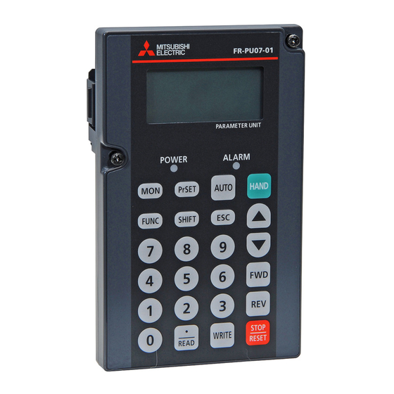
Unpacking and Product Confirmation 1.2.2 Appearance and parts identification Unpack the parameter unit, check the name plate on the back, and make sure that the product has not been damaged before using. FR-PU07 Front Rear POWER lamp Connector for inverter Lit when the power turns ON. - Page 15 Unpacking and Product Confirmation FR-PU07BB Rear Connector for PU cable Power supply Connect using the connection switch cable (FR-CB2 (Refer to page 18, 19) Connector for AC adapter Pull out the protective cover toward you to remove and then connect the AC adapter (sold separately).
-
Page 16: Explanation Of Keys
Unpacking and Product Confirmation 1.2.3 Explanation of keys Description Used to select the parameter setting mode. Press to select the parameter setting mode. Used to display the first priority screen. Used to display the output frequency when making an initial setting. Operation cancel key. -
Page 17: Key Description
Unpacking and Product Confirmation Description Forward rotation command key. Reverse rotation command key. · Stop command key. · Used to reset the inverter when a fault occurs. · Used to write a set value in the setting mode. · Used as a clear key in the all parameter clear or alarm history clear mode. ·... -
Page 18: Installation And Removal Of Fr-Pu07
Installation and Removal of FR-PU07 Installation and Removal of FR-PU07 To ensure safety, install or remove FR-PU07 after switching the power of the inverter OFF. FR-PU07 cannot be directly installed to the FR-E700, D700 inverter. 1.3.1 Direct installation to the inverter (A700/F700 series) (1) Remove the operation panel (FR-DU07). -
Page 19: Removal From The Inverter (A700/F700 Series)
Installation and Removal of FR-PU07 1.3.2 Removal from the inverter (A700/F700 series) Loosen the fixed screws, hold down the right and left hooks of the FR-PU07, and then pull the parameter unit toward you. Press the hooks. Fixed screw... -
Page 20: Installation Using The Connection Cable (Fr-Cb2)
(1) Remove the operation panel (FR-DU07). (2) Securely insert one end of connection cable into the PU connector of the inverter and the other end into the connection connector of FR-PU07 along the guides until the stoppers are fixed. Stopper... - Page 21 (1) Open the PU connector cover. (2) Securely insert one end of connection cable into the PU connector of the inverter and the other end into the connection connector of FR-PU07 along the guides until the stoppers are fixed. Stopper...
-
Page 22: Removal When The Connection Cable (Fr-Cb2) Is Used
(1) Remove the inverter front cover. (For the removal of the front cover, refer to the inverter manual.) (2) Securely insert one end of connection cable into the PU connector of the inverter and the other end into the connection connector of FR-PU07 along the guides until the stoppers are fixed. PU connector... -
Page 23: Connection And Removal Of Fr-Pu07Bb
Connection and Removal of FR-PU07BB Connection and Removal of FR-PU07BB 1.4.1 Before using FR-PU07BB in the battery mode For the power supply of FR-PU07BB, a battery and an AC adapter (sold separately) are available. (1) When using a battery 1) Loosen the screw of the FR-PU07BB rear side. 3) Place batteries as shown below. - Page 24 Connection and Removal of FR-PU07BB (2) When using an AC adapter 2) Connect the AC adapter (sold separately) to a AC power 1) Pull out the protective cover toward you to remove supply. and then insert the output plug of an AC adapter (sold separately) into the AC adapter connector.
- Page 25 Use the following adapter to use the FR-PU07BB with single phase 100V power supply. Product name Model Manufacturer AC adapter TAS2900-PUA Mitsubishi Electric System & Service Co., Ltd. AC adapter cable length 1500mm 1950mm 100 General specifications Refer to the specifications below for an adapter to use the FR-PU07BB with AC power supply.
-
Page 26: Instructions For The Fr-Pu07Bb (Battery Mode)
Connection and Removal of FR-PU07BB 1.4.2 Instructions for the FR-PU07BB (battery mode) (1) Functions available when using in the battery mode Description Remarks · Parameter read/write for plug-in option can be Parameter · Parameter read done in battery mode independently of whether change ·... -
Page 27: Connecting To Fr-A700/F700 Using The Connection Cable (Fr-Cb2)
Connection and Removal of FR-PU07BB 1.4.3 Connecting to FR-A700/F700 using the connection cable (FR-CB2) (1) Remove the operation panel (FR-DU07). (2) Insert one end of connection cable securely into the PU connector of the inverter and the other end into the connection connector of FR-PU07BB along the cable guides until the stoppers are fixed. -
Page 28: Connecting To Fr-E700 Using The Connection Cable (Fr-Cb2)
Connection and Removal of FR-PU07BB 1.4.4 Connecting to FR-E700 using the connection cable (FR-CB2) (1) Open the PU cover of the inverter. (2) Insert one end of connection cable securely into the PU connector of the inverter and the other end into the connection connector of FR-PU07BB along the cable guides until the stoppers are fixed. -
Page 29: Parameters To Be Checked First
Parameters to be Checked First Parameters to be Checked First Change the following parameter settings as required. For the changing procedures, refer to page 33. 1.5.1 PU display language selection (Pr. 145) By setting the Pr. 145 PU display language selection value, you can select the language displayed on the parameter unit. -
Page 30: Pu Contrast Adjustment (Pr. 991)
Parameters to be Checked First 1.5.3 PU contrast adjustment (Pr. 991) By setting the Pr. 991 PU contrast adjustment value, you can adjust the contrast for the display panel of the parameter unit. Pr. 991 Setting Description 0 to 63 Light Initial value Dark... -
Page 31: Functions
FUNCTIONS Monitoring Function 2.1.1 Display overview READ :List 120.00 (1) Main monitor (2) Rotation direction indication (3) Operating status indication (1) Main monitor (2) Rotation direction indication Shows the output frequency, output current, output Display the direction (forward rotation/reverse voltage, alarm history and other monitor data. rotation) of the start command. - Page 32 Monitoring Function READ :List (6) Warning indication 120.00 (5) Unit indication (4) Operating mode indication (4) Operation mode indication (6) Warning indication Displays the status of the operation mode. Displays an inverter warning. : External operation mode The warning type varies with the inverter model. : PU operation mode Refer to the inverter instruction manual for details.
- Page 33 Monitoring Function REMARKS · Standby mode function When FR-PU07BB gets into the standby mode, the backlight of the parameter unit turns OFF, and POWER LED remains lit. <Switching conditions> ·When the FR-PU07BB is left in the power-ON status for one minute without connecting to the inverter. ·When FR-PU07BB is connected to the inverter and the inverter remains in the reset status for one minute.
-
Page 34: Using "Shift" To Change The Main Monitor
Monitoring Function 2.1.2 Using to change the main monitor " S H I F T " When "0" (initial value) is set in the Pr. 52 DU/PU main display data selection, simply pressing calls 6 different monitor screens in sequence. Switch power ON or press When output frequency... -
Page 35: Setting The Power-On Monitor (The First Priority Monitor)
Monitoring Function 2.1.3 Setting the power-ON monitor (the first priority monitor) Set the monitor which appears first when power is switched ON or is pressed. • When you press during any monitor screen other than ALARM HISTORY being displayed, that screen is set as the power-ON screen and will be displayed first. -
Page 36: Using "Read" To Change The Main Monitor
Monitoring Function 2.1.4 Using to change the main monitor " R E A D " Press to display the monitoring list while the main monitor is displayed. Select a monitor from the monitoring list to change the main monitor. Example: Select the output current peak value monitor. The selected monitor is not set as the first priority monitor yet when only was pressed. -
Page 37: Using The Parameter To Change The Monitor (Pr. 52)
Monitoring Function 2.1.5 Using the parameter to change the monitor (Pr. 52) To change the third monitor (output voltage monitor), set Pr. 52 DU/PU main display data selection. (Note that setting "17" (load meter) , "18" (Motor excitation current) , and "24" (Motor load ratio) *1 *2 change the output current monitor. - Page 38 Monitoring Function Factory setting * The monitor displayed at powering ON is the first priority monitor. Refer to page 26 for the setting method of the first priority monitor. First priority monitor Second monitor Third monitor READ:List READ:List READ:List 0.00 0.00 0.00 --- STOP EXT...
-
Page 39: Frequency Setting
Frequency Setting Frequency Setting The frequency in PU operation mode and External/PU combined operation mode (Pr. 79 = "3") can be set. REMARKS When changing the operation mode from External operation mode to PU operation mode, operation mode can not be changed if the external starting signal (STF or STR) is ON. -
Page 40: Step Setting
Frequency Setting 2.2.2 Step setting Change frequency continuously using You can change the frequency only while you press . Since the frequency changes slowly at first, this setting can be used for fine adjustment. REMARKS Press Freq Set Change of frequency can be made during operation by 0.00Hz The frequency setting screen the step setting. -
Page 41: Precautions For Frequency Setting
Frequency Setting 2.2.3 Precautions for frequency setting 1) Pr. 79 Operation mode selection must have been set to switch to the PU operation. (Refer to the inverter instruction manual for details of Pr. 79 .) 2) In the monitor mode, you cannot make the direct setting (Refer to page 30) to set the running frequency. Perform the step setting (Refer to page 31) and press , or press to display the frequency setting... -
Page 42: Setting And Changing The Parameter Values
Setting and Changing the Parameter Values Setting and Changing the Parameter Values Using the FR-PU07/FR-PU07BB allows you to read the parameter of inverter or change the set value easily. Refer to the inverter instruction manual for details of the parameters. -
Page 43: Selecting The Parameter From Functional List To Change The Set Value
Setting and Changing the Parameter Values 2.3.2 Selecting the parameter from functional list to change the set value Example: When changing 5s to 180s at the Pr. 8 Press Deceleration time setting 1 Accl/Decl T A function list regarding 2 Accl/Decl P 3 Brake Seq acceleration/deceleration is Press... - Page 44 Setting and Changing the Parameter Values (1) Direct setting Press Enter the desired value. 8 Dec.T1 5.0S (2)Step setting 180S 0~3600 Press Display "180" using Press 8 Dec.T1 180.0S 180.0S The set value is changed. Completed Press to display the next parameter. is pressed when an incorrect setting value is input, the display returns to the list display "8".
-
Page 45: Selecting The Parameter From Parameter List To Change The Set Value
Setting and Changing the Parameter Values 2.3.3 Selecting the parameter from parameter list to change the set value Example: When changing 5s to 180s at the Pr. 8 Select the parameter. Deceleration time setting When moving the cursor 8 Dec.T1 5.0S using and pressing... -
Page 46: Selecting The Parameter From User List To Change The Set Value
Setting and Changing the Parameter Values 2.3.4 Selecting the parameter from User List to change the set value If a parameter is registered to User List, the parameter can be read from User List and changed. (For registering the user group, refer to page 39 .) Example: When changing 5s to 180s at the Pr. -
Page 47: Precautions For Setting Write
Setting and Changing the Parameter Values 2.3.5 Precautions for setting write · Perform parameter setting change during an inverter stop basically in the PU operation mode or combined operation mode. The parameter setting can not be changed in the External operation mode or during inverter operation. -
Page 48: User Group Function
User Group Function User Group Function · User group function is a function to display only parameters necessary for setting. · Among all parameters, maximum 16 parameters can be registered to the user group. When "1" is set in Pr. 160, only parameters registered in the user group can be accessed for reading and writing. (The parameters not registered to the user group cannot be read.) REMARKS FR-D700 does not have the user group function. -
Page 49: Registering The Parameters To User Group
User Group Function 2.4.1 Registering the parameters to user group Register. Press When moving the cursor to "YES" and pressing SETTING MODE The parameter unit is in the 0~9:Ser Pr.NO. , the registration is executed. parameter setting mode. Select Oper The parameter setting Read the parameters. -
Page 50: Deleting The Parameters From User Group
User Group Function 2.4.2 Deleting the parameters from To continue deleting 1 Max.F1 user group parameter, repeat the 2 Min.F1 operation from step 3. 7 Acc.T1 8 Dec.T1 Press SETTING MODE 0~9:Ser Pr.NO. 2.4.3 Confirming the parameters The parameter unit is in the parameter setting mode. -
Page 51: Calibration Of The Meter (Frequency Meter)
Calibration of the Meter (Frequency Meter) Calibration of the Meter (Frequency Meter) The functions vary with the inverter. (Refer to the inverter instruction manual for details of the parameters.) 2.5.1 Calibration of the FM terminal Parameter Enter Pr. 900 FM terminal calibration 900 FM Tune press Run Inverter... -
Page 52: Calibration Of The Am Terminal
Calibration of the Meter (Frequency Meter) 2.5.2 Calibration of the AM terminal Press 900 FM Tune Completed Parameter Calibration is complete. <MONITOR> Pr. 901 AM terminal calibration Pr. 158 AM terminal function selection Press to return to the Pr. 55 Frequency monitoring reference READ:List main monitor screen. - Page 53 Calibration of the Meter (Frequency Meter) (2) When calibrating output current Enter and press For the output current or another item, which does 901 AM Tune Run Inverter not easily point 100% value during operation, 60Hz adjust the reference voltage output, then select the 60Hz is set.
- Page 54 Calibration of the Meter (Frequency Meter) Press Enter SETTING MODE 0~9:Ser Pr.NO. The parameter unit is in the 901 AM Tune press Run Inverter parameter setting mode. Select Oper 0.00Hz The present Pr. 901 setting appears. Enter 158 AM set Enter and press press...
-
Page 55: Adjustment Of The Frequency Setting Signals "Bias" And "Gain
Adjustment of the Frequency Setting Signals "Bias" and "Gain" Adjustment of the Frequency Setting Signals "Bias" and "Gain" The functions vary with the inverter model. (Refer to the inverter instruction manual for details of the functions.) 2.6.1 Adjustment procedure There are three ways to adjust the bias and gain of the frequency setting voltage (current). (1) Adjust only the bias and gain frequencies and not adjust the voltage (current) (Refer to page 47) (2) Adjust any point by applying a voltage across terminals 2-5 (starting a current across terminals 4-5) (Refer to page 49) - Page 56 Adjustment of the Frequency Setting Signals "Bias" and "Gain" (1) Adjust only the bias and gain frequencies and Press not adjust the voltage The bias frequency is set at Setting of the frequency setting voltage bias • 10Hz. Press Freq Set 902 Ext2bias 0.00Hz The frequency setting screen...
- Page 57 Adjustment of the Frequency Setting Signals "Bias" and "Gain" Setting of the frequency setting voltage gain • REMARKS The current input (Pr. 904) can also be adjusted Press 903 Ext2gain using a similar procedure. 60.00Hz The present setting appears. The Pr. 903 Terminal 2 frequency setting gain remains Set<WRITE>...
- Page 58 Adjustment of the Frequency Setting Signals "Bias" and "Gain" (2) Adjust any point by application of voltage to Enter across terminals 2-5 Set the bias frequency at Setting of the frequency setting voltage bias • 10Hz. 902 Ext2bias 10.00Hz Press 0.5% Freq Set 20.0%...
- Page 59 Adjustment of the Frequency Setting Signals "Bias" and "Gain" Setting of the frequency setting voltage gain • Press Press , then The gain frequency is set at 903 Ext2gain 60.00Hz 50Hz for 5V input. The present Pr. 903 setting 97.1% 903 Ext2gain Setting is completed as appears.
- Page 60 Adjustment of the Frequency Setting Signals "Bias" and "Gain" (3) Adjust any point without application of voltage Enter to across terminals 2-5 902 Ext2bias 10Hz Set the bias frequency at • Setting of the frequency setting voltage bias -0.5% 10Hz. -0.5% Press Freq Set...
- Page 61 Adjustment of the Frequency Setting Signals "Bias" and "Gain" • Setting of the frequency setting voltage gain Press Press , then The gain frequency is set at 903 Ext2gain 60.00Hz 50Hz. The present Pr. 903 setting 97.1% Setting is completed as value appears.
-
Page 62: Function Menu
Function menu Function Menu Description Refer To The monitor list appears, and you can change from one monitor to FR-PU07 another and set the first priority monitor. 1. MONITOR Page 59 FR-PU07BB Monitor is available. (However, the monitored value other than the battery mode value of the frequency setting monitor is displayed as 0.) - Page 63 9. S/W This function displays the software control number of the inverter. This function displays the signals assigned to the I/O terminals of the FR-PU07 control circuit and the ON/OFF states of the signals. 10. Selectop Page 74...
-
Page 64: Function Menu Transition
Overview of Function Menu 3.1.2 Function menu transition 1 MONITOR Frequency [Hz] 1 Frequency 2 PU Oper Current [A] 2 Current Voltage [V] 3 Voltage Fault description * The latest 8 faults are displayed 4 Alarm His Frequency setting (shows the frequency already set)[Hz] 5 F Command Running speed (shows the motor speed or moving speed)[r] 6 RPM... - Page 65 Overview of Function Menu 1 Setting Mode SETTING MODE 1 Appl.Grp 2 Pr.List 0~9:Ser Pr.No. 2 Pr.List 3 User List 3 Set Pr.List 4 Def.Pr.List Select Oper 4 Param Copy 0 Trq Bst1 0 Trq Bst1 6.0% 1 Max.F1 2 Min.F1 3 Pr.List 0~30 3 VFbaseF1...
- Page 66 Overview of Function Menu INV.RESET Exec<WRITE> Cancel<ESC> [Estimated cause] 1 M.Not Run M.NOT RUNNING 2 M.Spd Error NO I/P Power 3 M.A/Dec Err or Phase Loss 4 M.Curr.High INV.Output V/f Setting 0.00Hz Error? See Pr.3,14, 0.00A 0.0V <SHIFT> 19,47,113 7 INV.Reset 8 T/Shooting 9 S/W 5.0S...
- Page 67 Overview of Function Menu Settings of Pr. 178 to Pr. 196 are displayed. Terminal Name <option> OP1: ---- OP2: ---- OP3: A7NC Param Copy Name:000 1 Copy area 1 :Select Char Overwrite area 1 2 Copy area 2 10 Selectop READ:Decide Char WRITE:Executing Reading...
-
Page 68: Operation Procedures For Functions
Operation Procedures for Functions Operation Procedures for Functions 3.2.1 Monitor function The monitoring list appears and you can change from one monitor screen to another and set the first priority screen. Press Press The function menu is called. The monitor screen selected READ:List Make sure that the by the cursor appears. -
Page 69: Selection Of Pu Operation (Direct Input)
Operation Procedures for Functions 3.2.2 Selection of PU operation (direct input) You can select the PU operation mode to set PU operation frequency. Enter the set frequency Press 1 MONITOR using and press 2 PU Oper The function menu is called. Freq Set 3 Pr.List 60.00Hz... -
Page 70: Selection Of The Pu Jog Operation Mode
Operation Procedures for Functions 3.2.3 Selection of the PU Jog operation mode You can select the PU Jog operation mode to set PU jog frequency. Enter the set frequency Press 1 MONITOR using and press The function menu is called. 2 PU Oper PU/JOG 3 Pr.List... -
Page 71: Parameters
Operation Procedures for Functions 3.2.4 Parameters When selecting the parameter on the function menu, the parameter menu is displayed, and you can perform the following operations for the parameters. Display Description Setting Mode Switches to the parameter setting mode to read and write the parameter setting. Displays the parameters list. - Page 72 Operation Procedures for Functions (1) "1 Setting Mode" Using , move the 1 Setting Mode 2 Pr.List Press cursor to "2 Pr. List". 1 MONITOR 3 Set Pr.List The function menu is called. 2 PU Oper 4 Def.Pr.List 3 Pr.List 4 Pr.Clear Press Using...
- Page 73 Operation Procedures for Functions (3) Display of "3 Set Pr.List" (4) Display of "4 Def.Pr.List" The initial values of parameters are displayed. Call the parameter menu 1 Setting Mode similarly to steps 1 to 3 of Call the parameter menu 2 Pr.List 1 Setting Mode page 63.
-
Page 74: Parameter Clear
Operation Procedures for Functions 3.2.5 Parameter clear You can perform the "parameter clear" and "all parameter clear". Switch to the PU operation mode before performing any operation. Clear Pr......Returns (initializes) the parameters to the factory settings with the exception of •... - Page 75 Operation Procedures for Functions (2) All parameter clear Call the parameter menu 1 Clear Pr. similarly to steps 1 to 3 of 2 Clear All page 65. Select the "Clear All". 1 Clear Pr. Using , move the 2 Clear All cursor to "2 Clear All"...
-
Page 76: Alarm History
Operation Procedures for Functions 3.2.6 Alarm history Shows the history of past eight faults. Press when displaying Press 1 MONITOR the operation mode for fault 2 PU Oper The function menu is called. 2nd Prev.ERR 3 Pr.List occurrence in steps 4 and 5 4 Pr.Clear PU Leave Out to display the operation data... -
Page 77: Alarm Clear
Operation Procedures for Functions 3.2.7 Alarm clear Clears all the fault history. Press 1 MONITOR 2 PU Oper The function menu is called. 3 Pr.List 4 Pr.Clear Using , move the 5 Alarm His cursor to "6 AlarmClear". 6 AlarmClear 7 INV.Reset Hold down and press... -
Page 78: Inverter Reset
Operation Procedures for Functions 3.2.8 Inverter reset Resets the inverter. REMARKS Press 1 MONITOR · If the inverter's protective function is activated to 2 PU Oper The function menu is called. bring the inverter to trip (output shutoff), execute the 3 Pr.List 4 Pr.Clear inverter reset only by pressing... -
Page 79: Troubleshooting
Operation Procedures for Functions 3.2.9 Troubleshooting If the inverter appears to operate improperly, perform the following operation to display the most likely cause of the fault. This operation may also be performed during inverter operation (PU operation, External operation) or during trip (protection activated). - Page 80 Operation Procedures for Functions Troubleshooting guidance 1) M.NOT RUNNING (Motor does not run) M.NOT RUNNING The protective function is M.NOT RUNNING The inverter cannot start because ALARM Max. F1<StartF activated to bring the inverter the inverter starting frequency Indicated Pr. 1 Pr.
- Page 81 Operation Procedures for Functions 2) M.SPEED ERROR 3) M.A/Dec Err (Speed does not match the running frequency (Actual acceleration/deceleration time is longer setting) than the Pr. 7/Pr. 8 setting) Since the running frequency setting is M. SPEED ERROR Acceleration time setting 5.0S SetF MaxF1/F2 <...
- Page 82 Operation Procedures for Functions 4) M.Curr.High (Inverter output current is larger than normal) Since the torque boost setting may be Trq. Bst First, the running frequency, output current and INV.Output Setting Err? inappropriate, check the following relevant output voltage of the inverter are displayed. 60.00Hz See Pr.
-
Page 83: Terminal Assignment (Selectop)
Operation Procedures for Functions 3.2.10 Terminal assignment (Selectop) The signals assigned to the control circuit terminals and their ON-OFF state are displayed. If the plug-in options FR-A7AX, FR-A7AY and FR-A7AR are mounted, the terminal state of the plug-in option can be also confirmed. Press Indicates Pr.178 to Pr.196 1 MONITOR... -
Page 84: Option
Operation Procedures for Functions 3.2.11 Option Displays what options are fitted to the option connectors. CAUTION Press 1 MONITOR Option fitting status monitor is not available in battery The function menu is called. 2 PU Oper mode. 3 Pr.List 4 Pr.Clear REMARKS Using , move the... -
Page 85: 3.2.12 Multiple Copies
(1) Copying the parameter settings Parameter settings of an inverter can be read. The settings of maximum three inverters can be stored in the FR-PU07. You can also copy the stored parameter settings to another inverter of the same series. Confirm for setting ·... - Page 86 • Reading the parameter settings of the inverter Give a name. and storing them to FR-PU07. You can name each of copy Select the areas 1 to 3. Connect the FR-PU07 to the copy source inverter. Name:012 characters with :Select Char Press READ:Decide Char...
- Page 87 "12 PRCpy set" and 11 Option 12 PRCpy set CAUTION press · Overwriting the data of the FR-PU07 deletes the Select the copy area. previous data. Point the cursor to the copy area that stores the 1 Copy area 1...
- Page 88 Operation Procedures for Functions (2) Verifying the parameters All the parameter settings stored in the FR-PU07 are verified with those which are stored in the inverter. REMARKS Verification cannot be performed between different inverter series. Select the "Verifying". Refer to page 77 and copy the parameter settings of the verify source inverter to the FR-PU07.
- Page 89 Operation Procedures for Functions If an error is detected during verification, the corresponding Pr. is shown. Param Copy Note that only "Verify Err" will Verify Err Verify Err be displayed if an incorrect Pr. 2 value has been entered Min.F1 directly (f setting) or set in either Pr.
-
Page 90: Other Precautions
Other Precautions Other Precautions 3.3.1 Precautions for parameter unit operation Note the following items when operating the parameter unit to prevent setting from being disabled or incorrect values from being entered. • Precautions for the digit count and decimal point of input value The maximum number of input digits is six including a decimal point. -
Page 91: Operation
OPERATION How to Select the Operation Mode 4.1.1 Switching from External 4.1.2 Switching from PU operation operation mode [EXT] to PU mode [PU] to External operation operation mode [PU] mode [EXT] Confirmation Confirmation Make sure that the external input signal (STF, STR) is OFF. Make sure that the external input signal (STF, STR) is OFF and that the operation command indication is "- - -". -
Page 92: Switching To The External / Pu Combined Operation Mode
How to Select the Operation Mode 4.1.3 Switching to the External / PU combined operation mode Changing the Pr. 79 Operation mode selection setting to "3" or "4" switches to the External / PU combined operation mode. "PU+E" is displayed in the operation mode indication position. READ:List 0.00 --- STOP PU+E... -
Page 93: How To Operate Pu Operation
How to Operate PU Operation How to Operate PU Operation 4.2.1 Normal operation During motor operation, the speed can be changed Step Operation Procedure Image by simply executing Step 2. Press 4. Stop Step Operation Procedure Image The motor is decelerated to Switch power ON. -
Page 94: Pu Jog Operation
How to Operate PU Operation 4.2.2 PU Jog operation Step Operation Procedure Image Press , then Hold down to perform operation, and The PU Jog operation mode release it to stop. 3. Jog operation mode selection is selected, and the PU Jog Jog operation cannot be performed in the following frequency setting screen cases:... -
Page 95: Combined Operation (Operation Using External Input Signals And Pu)
Combined Operation (Operation Using External Input Signals and PU) Combined Operation (Operation Using External Input Signals and PU) 4.3.1 Entering the start signal from outside and setting the running frequency from the PU (Pr. 79 = 3) Step Operation Procedure Image The external frequency setting signals and Set the start switch (STF... -
Page 96: Entering The Running Frequency From Outside And Making Start And Stop From The Pu (Pr. 79 = 4)
Combined Operation (Operation Using External Input Signals and PU) 4.3.2 Entering the running frequency from outside and making start and stop from the PU (Pr. 79 = 4) Step Operation Procedure Image Step Operation Procedure Image Switch the power ON. Press of the 1. -
Page 97: Entering The Start Signal And Multi-Speed Signal From Outside And Setting Multiple Speeds From The Parameter Unit
Combined Operation (Operation Using External Input Signals and PU) 4.3.3 Entering the start signal and multi-speed signal from outside and setting multiple speeds from the parameter unit Step Operation Procedure Image Step Operation Procedure Image Change the multi-speed Switch the power ON. frequency during 1. -
Page 98: Check First When You Have A Trouble
CHECK FIRST WHEN YOU HAVE A TROUBLE Troubleshooting If a fault occurs and the inverter fails to operate properly, locate the cause of the fault and take proper corrective action by referring to the troubleshooting below. If the corresponding information is not found in the table, the inverter has problem, or the component parts are damaged, contact your sales representative. - Page 99 Troubleshooting Status Possible causes Check point Corrective action Check whether RES signal is During inverter reset Turn OFF the RES signal. Check that no cable damage Replacement of a cable Connection fault of a cable or nor connection fault of a Check for a connector connector The "MITSUBISHI"...
-
Page 100: Specifications
SPECIFICATIONS Standard Specifications Specifications Item FR-PU07 FR-PU07BB Surrounding air temperature -10°C to +50°C (non-freezing) *1 Ambient humidity 90%RH or less (non-condensing) Storage temperature -20°C to +65°C *2 Ambience Indoors (free from corrosive gas, flammable gas, oil mist, dust and dirt) Maximum 1000m above sea level for standard operation. - Page 101 Standard Specifications • FR-PU07BB dedicated specifications Item Specifications Alkaline battery Nickel metal hydride battery A700/F700 E700 A700/F700 E700 Battery life Approx. 90 min Approx. 150 min Approx. 120 min Approx. 300 min Battery exhaustion Battery life * warning lamp color changing start time Approx.
-
Page 102: Outline Drawing And Panel Cutting Drawing
(Unit : mm) 80.3 When installing the FR-PU07 on the enclosure, etc., remove screws for fixing the FR-PU07 to the inverter or fix the screws to the FR-PU07 with M3 nuts. Select the installation screws of which length will not exceed the effective depth of the installation screws threads. -
Page 103: Fr-Pu07Bb Outline Dimension Drawings
Outline Drawing and Panel Cutting Drawing 6.2.2 FR-PU07BB outline dimension drawings <Outline drawing> 46.7 44.7 * FR-PU07BB cannot be installed to the enclosure and such. (Unit: mm) -
Page 104: Appendix
APPENDIX Appendix 1 Disposing of the equipment in the EU countries • The symbol shown below, which is printed on the product for EU countries, means that electric and electronic equipment, at their end-of-life, should be disposed of separately from your household waste. •... - Page 105 REVISIONS *The manual number is given on the bottom left of the back cover. Print Date *Manual Number Revision Aug., 2005 IB(NA)-0600240ENG-A First edition Additions May, 2007 IB(NA)-0600240ENG-B · FR-PU07BB · Disposing of the equipment in EU countries Mar., 2008 IB(NA)-0600240ENG-C ·Partial changes Additions Jan., 2009...