Rangemaster Classic Deluxe 110 Dual Fuel User's Manual & Installation Instructions
Hide thumbs
Also See for Classic Deluxe 110 Dual Fuel:
- User's manual & installation instructions (56 pages) ,
- User manual (40 pages) ,
- Users manual & installation (44 pages)

Related Manuals for Rangemaster Classic Deluxe 110 Dual Fuel


Summary of Contents for Rangemaster Classic Deluxe 110 Dual Fuel
-
Page 1: User Guide
Britain’s No.1 Range Cooker USER GUIDE & INSTALLATION INSTRUCTIONS Classic Deluxe 110 Dual Fuel... - Page 2 We offer cookware to work perfectly with all fuel types manufactured by Rangemaster, including induction hobs. You can be assured of functionality with style, as well as the quality and meticulous attention to detail you expect from the pioneers of range cooking.
-
Page 3: Table Of Contents
Tap Adjustment Cooking Table Stick on Label Pressure Testing Cleaning Your Cooker Circuit Diagram Essential Information Hotplate Burners 10. Technical Data Ceramic Hotplate The Griddle Glide-out Grill™ Control Panel and Doors Ovens Cleaning Table Classic Deluxe 110 Dual Fuel U108820-15B... -
Page 5: Before You Start
1. Before You Start... If you smell gas Your cooker should give you many years of trouble-free cooking if installed and operated correctly. It is important • DO NOT turn electric switches on or off. that you read this section before you start, particularly if you •... -
Page 6: Ceramic Warming Zone
NEVER leave a chip pan unattended. Always heat fat Accessible parts will become hot during use and will slowly, and watch as it heats. Deep fry pans should retain heat even after you have stopped cooking. be only one third full of fat. Filling the pan too full Keep babies and children away from the cooker and of fat can cause spill over when food is added. -
Page 7: Cooker Care
Take care NOT to place metallic objects such as Fig.1.1 knives, forks, spoons and lids on the hob surface since they can get hot. The appliance is not intended to be operated by means of external timer or separated remote-control system. -
Page 8: Cooker Overview
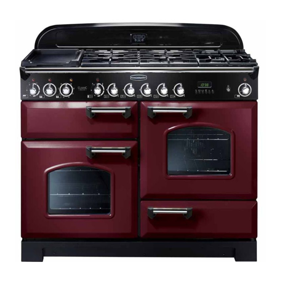
2. Cooker Overview Fig.2.1 ArtNo.212-0019 - 110 DF Classic Deluxe front view The 110 dual fuel cooker (Fig.2.1) has the following features: Fig.2.2 Four hotplate burners with a wok burner and ceramic multi-zone hotplate A control panel A glide-out grill A multi-function oven A fan oven A storage drawer... -
Page 9: Wok Burner
The igniter should spark and light the gas. Keep holding the Fig.2.3 knob pressed in to let the gas through to the burner for about ten seconds. If, when you let go of the control knob, the burner goes out, then the FSD has not been bypassed. -
Page 10: The Ceramic Hotplate
The cradle will get very hot in use – allow plenty of time for it Fig.2.11 to cool before you pick it up. The Ceramic Hotplate The hotplate area on the left-hand side is dual purpose. It can be used either as a ceramic hob to heat a pan in the usual way (Fig.2.11) or it can be used to heat the supplied griddle. -
Page 11: The Griddle
The Griddle Fig.2.16 The griddle (Fig.2.16) is designed to fit securely on the locating pins over the ceramic heating area (Fig.2.17). Do not try to use it over one of the gas burners. It will not be securely held and you may damage the non-stick finish. There are two elements that allow either the whole of the area to be heated or just the rear half. -
Page 12: The Glide-Out Grill
The Glide-out Grill Fig.2.21 Open the door and pull the grill pan carriage forward using the handle (Fig.2.21). The grill has two elements that allow either the whole area of the pan to be heated or just the right-hand half. To heat the whole grill, turn the control knob clockwise (Fig.2.22). - Page 13 Rangemaster fan ovens heat Conventional Oven (Top and Base Heat) up quickly; but the Rapid Response feature speeds this This function combines the heat from the top and process up enabling you to commence cooking sooner.
-
Page 14: Operating The Ovens
Right-hand Fan Oven Fig.2.24 The right-hand oven is a fan oven that circulates hot air ArtNo.235-0003 - Classic DL MF knobs continuously, which means faster, more even cooking. The recommended cooking temperatures for a fan oven are generally lower than a conventional oven. Note: Please remember that all cookers vary so temperatures in your new ovens may differ to those in your previous cooker. -
Page 15: The Clock
The Clock Fig.2.28 You can use the timer to turn the left-hand multi-function oven on and off. The clock must be set to the time of day before the ovens will work. Setting the Time of Day ArtNo.302-0002 - 6BC annotated The 6-button LCD clock is shown in Fig.2.28. -
Page 16: Accessories
AUTO is Showing, But you Want to Reset to Fig.2.38 Fig.2.39 Manual Cooking To return to manual cooking from any automatic setting, the ‘cook period’ must be cancelled. Press and hold the [E] button and then press the [ –] button until the display reads ArtNo.302-0009 - Activating ArtNo.302-0008 - the key lock 2... -
Page 17: Oven Lights
The Handyrack (Left-hand Oven) Fig.2.47 The Handyrack (Fig.2.47) fits to the left-hand oven door only. Food cooking on it is easy to attend to, because it is accessible when the door is open. The maximum weight that can be held by the Handyrack is 5.5 kg (12 lb). -
Page 18: Cooking Tips
3. Cooking Tips Tips on Cooking with the Timer General Oven Tips If you want to cook more than one dish, choose dishes that The wire shelves should always be pushed firmly to the back require approximately the same cooking time. However, of the oven. -
Page 19: Cooking Table
4. Cooking Table DocNo.031-0004 - Cooking table - electric & fan single cavity The oven control settings and cooking times given in the table below are intended to be used Top (T) AS A GUIDE ONLY. Individual tastes may require the temperature to be altered to provide a ArtNo.050-0007 preferred result. -
Page 20: Cleaning Your Cooker Essential Information
5. Cleaning Your Cooker Essential Information Fig. 5.1 Isolate the electricity supply before carrying out any thorough cleaning. Allow the cooker to cool. NEVER use paint solvents, washing soda, caustic cleaners, biological powders, bleach, chlorine based bleach cleaners, coarse abrasives or salt. DO NOT mix different cleaning products –... -
Page 21: Ceramic Hotplate
Ceramic Hotplate Fig. 5.5 Daily Care First of all, be sure that the heat indicator light is off and that the cooking surface is cool. Apply a small dab of ceramic cleaning cream in the centre of the area to be cleaned. Dampen a clean paper towel and work the cream onto the cooking surface. -
Page 22: Glide-Out Grill
Glide-out Grill™ Fig. 5.6 The grill pan and trivet should be washed in hot soapy water. Alternatively, the grill pan can be washed in a dishwasher. After grilling meats or any foods that soil, leave to soak for a few minutes immediately after use. Stubborn particles may be removed from the trivet using a nylon brush. -
Page 23: Control Panel And Doors
Control Panel and Doors Fig. 5.10 Avoid using any abrasive cleaners, including cream cleaners. For best results, use a liquid detergent. The same cleaner can be used on the doors, or alternatively, using a soft cloth wrung out in clean hot soapy water – but take care that no surplus water seeps into the appliance. -
Page 24: Cleaning Table
Cleaning Table Cleaners listed (Table 5-1) are available from supermarkets or electrical retailers as stated. For enamelled surfaces use a cleaner that is approved for use on vitreous enamel. Regular cleaning is recommended. For easier cleaning, wipe up any spillages immediately. Hotplate Part Finish... -
Page 25: Troubleshooting
6. Troubleshooting Hotplate ignition or hotplate burners faulty Power failure Is the power on? Is the clock illuminated? In the event of a failure in the electrical supply, remember to reset the clock to make sure that the If not, there maybe something wrong with the power timed oven continues to operate. - Page 26 An oven light is not working Fig.6.1 The bulb has probably burnt out. You can buy a replacement bulb (which is not covered under the warranty) from a good electrical shop. Ask for a 15 W – ArtNo.324-0005 Oven light bulb 230 V lamp, FOR OVENS.
-
Page 27: Installation
INSTALLATION Check the appliance is electrically safe and gas sound when you have finished. 7. Installation Dear Installer Safety Requirements and Regulations Before you start your installation, please complete the details This cooker must be installed in accordance with the relevant instructions in this booklet, with the below, so that, if your customer has a problem relating to relevant national and local regulations, and with your installation, they will be able to contact you easily. -
Page 28: Location Of Cooker
INSTALLATION Check the appliance is electrically safe and gas sound when you have finished. Checking the parts: Location of Cooker The cooker may be installed in a kitchen/kitchen diner but 3 pan supports Wok cradle NOT in a room containing a bath or shower. This appliance is designed for domestic cooking only. -
Page 29: Positioning The Cooker
INSTALLATION Check the appliance is electrically safe and gas sound when you have finished. Positioning the Cooker Fig.7.1 Fig.7.1 and Fig.7.2 show the minimum recommended 75 mm 75 mm distance from the cooker to nearby surfaces. 650 mm The cooker should not be placed on a base. The hotplate surround should be level with, or above, any adjacent work surface. -
Page 30: Fitting The Stability Bracket Or Chain
INSTALLATION Check the appliance is electrically safe and gas sound when you have finished. Lowering the Two Rear Rollers Fig.7.5 To adjust the height of the rear of the cooker, first fit a 13 mm spanner or socket wrench onto the hexagonal adjusting nut (Fig.7.5). -
Page 31: Fitting The Handles And Handrail
INSTALLATION Check the appliance is electrically safe and gas sound when you have finished. Fitting the Handles and Handrail Fig.7.10 Remove the 4 mm Allen screws from the doors (Fig.7.10). Fit the door handles and secure using the 4 mm screws (Fig.7.11). -
Page 32: Electrical Connection
INSTALLATION Check the appliance is electrically safe and gas sound when you have finished. Turn off the burners. Make sure that you reassemble the Current Operated Earth Leakage Breakers burner top in the correct way on the burner body. The combined use of your induction cooker and other Electrical Connection domestic appliances may cause nuisance tripping, so we recommend that the cooker is protected on an individual... -
Page 33: Conversion To Lp Gas
8. Conversion to LP Gas Check the ‘Technical Data’ section at the back of the book Fig.8.1 that the hob is convertible to the gas you want to use. A suitably competent person must perform the conversion. After conversion the installation must comply with the relevant regulations and also the local electricity supply company requirements. -
Page 34: Pressure Testing
Pressure Testing Connect the appliance to the gas supply. Check the appliance is gas sound. The gas pressure can be measured at one of the hotplate injectors (not a wok burner). Lift off a burner head. Fit the pressure gauge to the jet. Turn on and light one of the other burners. -
Page 35: Circuit Diagram
9. Circuit Diagram 1.1kW 1.1kW P038434 P095199 br br br br The connections shown in the circuit diagram are for single-phase. The ratings are for 230 V 50 Hz. Code Description Code Description Code Colour Grill energy control Right-hand fan oven thermostat Blue Grill element left-hand side Right-hand fan oven control... -
Page 36: Technical Data
10. Technical Data THIS COOKER IS CATEGORY: CatII 2H3+. It is supplied set for group H natural gas. A conversion kit from NG to LP is available for the cooker. INSTALLER: Please leave these instructions with the user. DATA BADGE LOCATION: Cooker back, serial number repeater badge below oven door opening. COUNTRY OF DESTINATION: GB, IE. - Page 37 Notes...
- Page 38 Notes...
- Page 39 0800 804 6261 or depending on your mobile network tariff you can call free on 0370 789 5107. For a competitive quote and to arrange for a Rangemaster approved engineer to attend, call Consumer Services on: 0800 804 6261 or...
- Page 40 Registered in England and Wales. Registration No. 354715 Registered Office: Juno Drive, Leamington Spa, Warwickshire, CV31 3RG Rangemaster continuously seeks improvements in specification, design and production of products and thus, alterations take place peri- odically. Whilst every effort is made to produce up-to-date literature, this booklet should not be regarded as an infallible guide to current...