Table of Contents
Advertisement
Advertisement
Table of Contents
Troubleshooting

Related Manuals for IPSO DR30SLG


Summary of Contents for IPSO DR30SLG
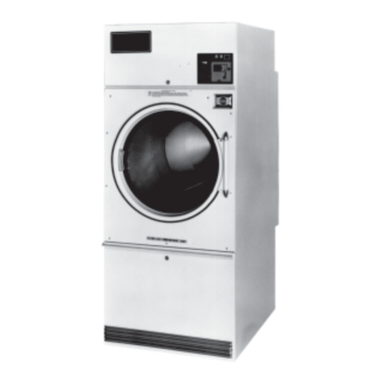
- Page 1 - USA OWNER'S MANUAL 30 Lb. Laundry Dryer MODELS STEAM ELECTRIC DR30SLG DR30SLS DR30SLE IPSO-USA 3101 S. Haven Hwy. 77 Phone: (850)271-8486 Suite A Panama City, FL 32405 THIS MANUAL MUST BE GIVEN TO THE EQUIPMENT OWNER. MAN2030I (ECN5752) 8/99...
-
Page 2: Important Notices
IMPORTANT NOTICES—PLEASE READ For optimum efficiency and safety, we recommend that you read the manual before operating the equipment. Store this manual in a file or binder and keep for future reference. WARNING: Purchaser must post the following notice in a prominent location: WARNING: For your safety, the information in this manual must be followed to minimize the risk of fire or explosion or to prevent property damage, personal injury or death. - Page 3 ATTENTION: L’ACHETEUR DOIT PLACER L’AVERTISSEMENT SUIVANT DANS UN ENDROIT CLAIR ET VISIBLE: AVERTISSEMENT. Assurez-vous de bien suivre les instructions donnees dans cette notice pour reduire au minimum le risque d’incendie ou d’explosion ou pour eviter tuot dommage materiel, toute blessure ou la mort. __ Ne pas entreposer ni utiliser d’essence ni d’autres vapeurs ou liquides inflammables dans le voisinage de cet appareil ou de tout autre...
- Page 4 WARNING: To avoid fire hazard, do not dry articles containing foam rubber or similar texture materials. Do not put into this dryer flammable items such as baby bed mattresses, throw rugs,undergarments (brassieres, etc.) and other items which use rubber as padding or backing. Rubber easily oxidizes causing excessive heat and possible fire.
-
Page 5: Dryer Warranty
IPSO’s factory, transportation prepaid, within the applicable warranty period and found by IPSO to have been defective, and in no event shall IPSO be liable for damages of any kind, whether for any injury to persons or property or for any special or consequential damages. -
Page 6: Table Of Contents
TABLE OF CONTENTS 30 LB. LAUNDRY DRYER PAGE PAGE Model Numbers & Company Address ......... 1 Service Savers ................34 Important Notices ..............2-4 Troubleshooting ..............35-38 Dryer Warranty ................5 Direct Spark Ignition .............. 39-40 Table of Contents ................. 6 General Maintenance ............ - Page 7 SYMBOLS The following symbols are used in this manual and/or on the machine: Symbol Description NOTE! Hot! Do Not Touch Heiß! Nicht Beruhren Haute temperature! Ne pas toucher Caliente! no tocar dangerous voltage tension dangereuse Gefährliche elektrische Spannung tension peligrosa marche conectado arrêt...
- Page 8 SYMBOLS Symbol Description rotation in two directions rotation dans les deux sens Drehbewigung in zwei Richtungen movimiento rotativo en los dos sentidos direction of rotation sens de mouvement continu de rotation Drehbewegung in Pfeilrichtung movimiento giratorio o rotatorio en el sentido de la flecha End of Cycle caution attention...
-
Page 9: Unpacking And General Installation
Unpacking/General Installation (All Dryers) Upon arrival of the equipment, any damage in shipment should be UNPACKING reported to the carrier immediately. Upon locating permanent location of a unit, care should be taken in movement and placement of equipment. See outline clearance diagrams for correct dimensions. Remove all packing material such as: tape, manuals, skid, etc. - Page 10 L28UR30 Outline Dimensions—Gas, Steam and Electric Models Page 10...
- Page 11 L28US30 Outline Dimensions—Gas Model Page 11...
-
Page 12: General Specifications
General Specifications GENERAL Basket Load Capacity ........30 lb (13.6 kg) Dryweight SPECIFICATIONS FOR Basket Size ........... 27 1/4" (720 mm) Diameter x 30 lb. LAUNDRY DRYERS 30 1/4" (760 mm) Deep Total Amps, Voltage, Cycle ......... Refer to rating plate on dryer Floor Space .......... -
Page 13: General Specifications
General Specifications Maximum Air Displacement ......700 cfm (1190 m³/h) 30 lb. STEAM MODEL SPECIFICATIONS Recommended Operating ......530-630 cfm Range (900-1070 m³h) Steam Supply Connection ......3/4" (DN20) Steam Return Connection ......3/4" (DN20) Operating Steam Pressure ......7-15 lb (3.18-6.9 kg) low pressure 100 lb (56.7 kg) high pressure... - Page 14 Main Drive Motors Motor No. Voltage Phase Amps MTR300 115/200-240 6.2/3.1 1725 MTR300 200-240 1425 MTR214 208-230/460 2.5/1.1 1725 MTR302 200-240/346-415 2.0/1.0 1425 MTR302 220/380 1.8/0.9 1725 Note: All motors have built-in thermal overload protection. Page 14...
-
Page 15: General Information
General Information GENERAL The dryer is so designed that when an operator opens the dryer door, INFORMATION the basket and exhaust fan stops. You can expect fast drying from a laundry dryer. Hot, dry air is properly and effectively moved through the basket and exhausted through a lint trap to the atmosphere. -
Page 16: Grounding Instructions
Grounding Instructions (Illustration) grounding method must comply with local electrical code requirements; or in the absence of local codes, with the National ELECTRICAL Electrical Code, ANSI/NFPA 70 or the Canadian Electrical Code, CONNECTIONS CA C22.1. See wiring diagram furnished with dryer. Your dryer is completely wired at the factory and it is only necessary for the electrician to connect the power leads to the wire connectors within the service connection box on the rear of the dryer. -
Page 17: Piping Recommendations
Piping Recommendations PIPING 1. Trap each dryer individually. Always keep the trap clean and in good working condition. RECOMMENDATIONS 2. When dryer is on the end of a line of equipment, extend header at least 4 feet (1.22 m) beyond dryer. Install globe valve, union, check valve and by-pass trap at end of line. -
Page 18: Gas Piping Installation
Gas Piping Installation GAS PIPING 1. The installation must conform with local codes, or in the absence of local codes with the National Fuel Gas Code, INSTALLATION ANSI Z223.1 or the CAN/CGA-B149, Installation Codes. 2. Check identification nameplate for type of gas for dryer. 3. - Page 19 Gas Piping Installation (Illustration) The dryer and it’s individual shutoff valve must be disconnected from the gas supply piping system during any pressure testing of that system at test pressures in excess of 1/2 psi (3.5 kPa). The dryer must be isolated from the gas supply piping system by closing it's individual manual shutoff valve during any pressure testing of the gas supply piping system at test pressures equal to or less than 1/2 psi (3.5 kPa).
-
Page 20: Gas Service Installation
Gas Service Installation Instructions The size of the gas service pipe is dependant upon many variables, GAS SERVICE such as tees, lengths, etc. Specific pipe size should be obtained from INSTALLATION the gas supplier. Refer to the “Gas Pipe Size” chart in this manual for INSTRUCTIONS general gas pipe size information. -
Page 21: Gas Pipe Size Chart
Gas Pipe Size Chart TOTAL BTU/HR GAS PIPE SIZE FOR 1000 BTU (250 KCAL) NATURAL GAS (for LP Gas correct AT 7” (17.8 CM) W.C. PRESSURE TOTAL total BTU/HR below by KCAL multiplying by .6) In figuring total length of pipe, make allowance for tees and elbows. HOUR (25 ft.) (50 ft.) - Page 22 Steam Piping Installation Instructions STEAM PIPING 1. Set and anchor dryer in position. Machine should be level to INSTALLATION assure proper steam circulation. INSTRUCTIONS 2. To prevent condensate draining from headers to dryer, piping should have a minimum 12" (305 mm) above respective header.
-
Page 23: Steam Piping Installation
Steam Piping Installation (Illustration) Page 23... -
Page 24: Dryer Installation With Multiple Exhaust
Dryer Installation With Multiple Exhaust For Exhaust Duct less than 14 feet (4.3 m) and 2 elbows equivalent and less than 0.3 inches (7.6 mm) water column static pressure. DRYER EXHAUSTS Area of section “A-A” must be equal to the sum of dryer exhaust pipes entering multiple exhaust pipe. -
Page 25: Dryer Installation With Multiple Exhaust
Dryer InstallationWith Multiple Exhaust For Exhaust Duct more than 14 feet (5 m) and 2 elbows equivalent and DRYER INSTALLATION more than 0.3 inches (8 mm) water column static pressure. WITH MULTIPLE EXHAUST (See illustration on next page.) 1. Make-up air from outside building may enter enclosure from top or side walls. -
Page 26: Dryer Installation With Separate Exhaust
Dryer Installation With Separate Exhaust (Preferred) DRYER INSTALLATION For ductwork less than 14 feet (5 m) and 2 elbows equivalent and less than WITH SEPARATE EXHAUST 0.3 inches (8 mm) water column static pressure: (PREFERRED) NEVER exhaust the dryer into a chimney. NEVER install wire mesh screen over the exhaust or make-up air area. - Page 27 Suggested Minimum Dryer Make-up Air Requirements Dryer Dryer Pocket Maximum Air Duct Size Required Model Capacity Flow Rate For Service Make-up Air per Pocket Connection Area per Pocket m3/h inch sq. inch cm2 C 30 13.6 1190 C 30 E/S 13.6 C 30 ST 13.6...
-
Page 28: Make -Up Air Requirements
Exhaust and Venting DRYER AIR FLOW Nothing is more important than air flow for the proper operation of a clothes INSTALLATION dryer. A dryer is a pump which draws make-up air from the out-of-doors, through the heater, through the clothes and then forces the air through the exhaust duct back to the out-of-doors. -
Page 29: Rules For Safe Operation Of Dryer
Rules for Safe Operation of Dryer 1. Be sure your dryer is installed properly in accordance with the RULES FOR SAFE recommended instructions. OPERATION OF DRYER 2. CAUTION Be safe—shut main electrical power supply and gas supply off externally before attempting service. 3. -
Page 30: Operating Instructions-Coin Meter Models
Operating Instructions—Coin Meter Models OPERATING INSTRUCTIONS—COIN METER MODELS OPERATING INSTRUCTIONS—COIN 1. After loading the dryer with water washed clothes, close the loading METER MODELS door. 2. ELECTRO-MECHANICAL COIN METER: Insert proper coin(s) in slot and turn knob until it stops. COMPUTERIZED COIN METER: Insert coin. - Page 31 Operating Instructions—Coin Meter Models IMPORTANT IMPORTANT If the tumbler door is opened during the drying cycle, the fan and heat will shut off. Press “START” button to resume the cycle. This dryer is designed for a capacity maximum load. Overloading it will result in longer drying time and damp spots on some of the load.
- Page 32 Setting Time On Computerized Coin Meter (Illustration) COMPUTERIZED COIN METER DIP Switch Banks are located here Page 32...
- Page 33 Setting Time On Computerized Coin Meter INSTRUCTIONS FOR 1. This control is equipped with two banks of four DIP switches. SETTING TIME ON COMPUTERIZED COIN 2. Each DIP switch bank consists of 4 small switches each with a METER specified amount of time (minutes), as shown: 1 min.
-
Page 34: Service Savers
Service Savers TROUBLESHOOTING To help you troubleshoot the dryer, we list below the most common reasons for service calls and some answers to the problems. Before you call service, please review the following items: DRYER WON’T START DRYER WON’T START 1. - Page 35 Troubleshooting Chart Troubleshooting Chart TROUBLE CAUSE REMEDY Motor will not start. No power. Check fuses on circuit breakers. Make sure main control switch is “on”. Check bonnet thermostat (gas only). Incorrect power. Check power source; voltage, phase and frequency must be the same as specified on electrical rating plate.
-
Page 36: Troubleshooting Chart
Troubleshooting Chart Troubleshooting Chart TROUBLE CAUSE REMEDY Dryer noisy or vibrating. Not leveled. Check manual for proper leveling procedures. Fan out of balance. Accidental damage to the fan blade can change the dynamic balance. Damaged fans should be replaced. Basket rubbing. Adjust basket clearance. -
Page 37: Direct Spark Ignition
Troubleshooting Chart Troubleshooting Chart TROUBLE CAUSE REMEDY Dryer runs, but no heat. Air switch out of adjustment. See air switch adjustment sheet. (continued) Air switch defective. Replace air switch. Gas pressure too low. Check manifold pressure and adjust to pressure specified on rating plate. - Page 38 Troubleshooting Chart Troubleshooting Chart TROUBLE CAUSE REMEDY Dryer too hot. Incorrect main burner orifice. Replace orifices. Check factory for correct size. Inadequate make-up air. Make-up air must be 4 to 6 times the exhaust area of the dryer. Lint accumulated. Remove lint.
- Page 39 Direct-Spark Ignition Operation NOTE: Some models are equipped with a dual ignition system. DIRECT SPARK The dual ignition system contains two direct spark IGNITION ignition modules in parallel. Each module has its own OPERATION flame sense circuit and acts independently of the other. If either bonnet limit thermostat opens because of high heat or flame impingement, the entire ignition system will shut down.
- Page 40 DIRECT SPARK IGNITION OPERATION FLOW CHART Page 40...
-
Page 41: General Maintenance
General Maintenance GENERAL 1. Clean lint trap daily. Remove lint before or after each day of MAINTENANCE operation. A clean lint trap will increase the efficiency of the dryer and the moisture-laden air will be exhausted outside more quickly. 2. Keep basket and sweep sheets clean. Clean as often as needed. -
Page 42: General Maintenance
General Maintenance GENERAL 7. Periodically clean and examine exhaust system. MAINTENANCE 8. Keep dryer area clean and free of gasoline, combustible materials and other flammable liquids or vapors. 9. Do not obstruct the flow of combustion (make-up) air and ventilating air. 10. -
Page 43: Burner Air Inlet Shutters Adjustment
Burner Air Inlet Shutter Adjustment Burner air inlet shutters are correctly adjusted when the flame is BURNER AIR INLET SHUTTER primarily blue. ADJUSTMENT BURNER AIR INLET TYPE OF GAS SHUTTER ADJUSTMENT Natural gas 1/2 Open Liquid petroleum 1/4 Open Manufactured gas 1/16 Open AIR SHUTTER AIR SHUTTER ADJUSTMENT:... -
Page 44: Burner Air Inlet Shutters Adjustment
Burner Air Inlet Shutter Adjustment Burner air inlet shutters are adjusted closed. Insufficient air is BURNER AIR admitted through the burner. Flame pattern is straight up and flame INLET SHUTTER is yellow. ADJUSTMENT WRONG—NEED TO ADJUST SHUTTER This flame pattern indicates the burner air inlet shutters are correctly BURNER AIR INLET adjusted, but air through the dryer is insufficient. -
Page 45: Bearing Replacement Instructions
Bearing Replacement Instructions BEARING REPLACEMENT Step 1 Remove belt guard, V-belt, spacer and basket INSTRUCTIONS sheave. Step 2 Loosen set screws on the flange bearing and on the pillow block bearing. Step 3 Remove the bolts holding the pillow block bearing and take it off the shaft. -
Page 46: Basket Alignment
Basket Alignment Instructions BASKET ALIGNMENT Step 1 Loosen the set screws on the flange and pillow block INSTRUCTIONS bearings. Step 2 Loosen the 4 side bolts, “1, 2, 3, 4” on the basket bearing bracket. (see figure 3) Loosen the two adjusting bolts and locknuts “5, 6”... - Page 47 Basket Shimming Instructions BASKET SHIMMING This procedure is normally necessary when replacing either the basket or the spider assembly on any dryer. Proper shimming is INSTRUCTIONS crucial to obtain a true running basket. A. Align the basket as per instructions in the manual. B.
-
Page 48: Air Switch Adjustment
Air Switch Adjustment (Illustration) AIR SWITCH 1. Shut off current; disconnect leads and remove air switch. ADJUSTMENT 2. Lay air switch assembly on flat surface. Adjust air blade at “A” (FIGURE 1) so that air blade lays flat and surface “B” is parallel to the flat surface. -
Page 49: Dryer - Front View
30 lb. Dryer—Front View (Illustration) Page 49... -
Page 50: Front Panel And Door Assembly
Parts—30 lb. Dryer (Front of Dryer) 1 TU7733 #8X1/2" Self Drill Screw 34 *TU9111 Thermostat Assembly 2 TU1771 #6 Twin Nut (Coin Meter Model Only) 3 TU1979 Door Switch 35 GA-00803-0 Cable, Hi-Voltage DSI 4 TU1770 Insulator 36 TU7690 Insulation 5 TU2373 Switch Bracket SB-00836-0 Screw, Phillips, Pancake Head... - Page 51 30 lb. Dryer—Rear View (Illustration) Page 51...
- Page 52 Parts—30 lb. Dryer (Rear of Dryer) 1 TU7733 #8 x 1/2" Self Drill Screw 37 TU5439 5/16"-18 x 3/4" Hex Head Screw 2 TU3211 3/8-16 x 2-1/2" Leveling Bolts 38- - Motor (Specify Motor No., 3 TU4937 3/8-16 Jam Nut Voltage, Cycle and Horsepower) 5 TU4787 3/8-16 Hex Nut...
- Page 53 Parts—Access Door and Control Panel—Computerized Coin Meter Access Door Assembly Ref. Nos. 1, 6-8, 30-31, 37-38 TU14567 Control Panel Assembly TU13724 - 24V 50/60 Hz. Gas 1 TU14662 Logo Decal 16 TU11510 Push Button Switch 2 TU3479 #10-32 x 7/16" Truss Head Screw 17 TU3400 3 P104 1/4"...
- Page 54 Parts—Access Door and Control Panel—Electro-Mechanical Coin Meter Access Door Assembly Ref. Nos. 1, 5-7, 18, 20, 29-30 TU14567 Control Panel Assembly TU13721 - 24V 50/60 Hz. Gas TU13847 - 24V 50/60 Hz. S/E 1 TU14568WHT Access Door Weldment (Specify Color) 14 FB187 #10 Lockwasher 2 TU3479...
- Page 55 TU14602 - Front Panel and Door Assembly (Illustration) 12 TU2090 Basket Door Seal 1 TU14601 Front Panel W/Door Catch - c/m 2 M262 #8-32 x 3/8" Truss Head Screw 13 TU4839 #10-32 x 3/8" Machine Screw 14 TU7862 Door GLass (Plain) 3 TU2194 Door Switch Actuator 4 TU2105...
- Page 56 Parts—Thermostat Assembly (Coin Meter Models) TU9111 (w/Illustration) 1 TU3240 Safety High Limit Thermostat 2 TU3240 185° F (85° C) Thermostat 3 TU5150 150° F (66° C) Thermostat 4 TU7244 135° F (57° C) Thermostat 5 TU5143 Mounting Bracket 6 TU3624 #6-32 x 1/4"...
- Page 57 Parts—Exhaust Duct Assembly (Energy-Saver Model Only) (w/Illustration) TU10269—Vertical Assembly Complete TU10336—Horizontal Assembly Complete 1 TU7733 #8 x 1/2" Self Drill Screw 2 TU8052 Tee - 8" x 6" x 6" 3 TU8176 Pipe - 8" x 17 1/2" 4 TU9161 Installation Label 5 TU10268 Elbow - 8"...
-
Page 58: Steam Heating Unit
Parts—Steam Heating Unit (w/Illustration) TU13689—9 Section Steam Bonnet Assembly w/Solenoid Valve 24V 1 TU2546 Housing Weldment 2 TU2547 Front Coil Retainer 3 TU2548 Rear Coil Retainer 4 TU2413 Steam Coil Manifold 5 TU2414 3/4" - 16 x 3/8" Straight Connector 6 TU2405 Steam Coil (9 required) 7 3/4"... -
Page 59: Gas Heating Unit
Gas Heating Unit (Regular Gas Fired Model) (Illustration) TU13673—(Natural Gas) TU13715—(LP Gas) 1 TU8631 Bonnet 13 TU2846 1/4" Split Lockwasher 2 TU13695 Bonnet Thermostat Bracket 14 TU4934 1/4"—20 Hex Nut 3 TU13212 1/2" Pipe Nipple—24" 15 TU2847 1/4"—Flat Washer 4 390401021 1/2"... -
Page 60: Gas Heating Unit
Parts—Gas Heating Unit (Energy-Saver Gas Model) TU13786—(Natural Gas) TU13785—(LP Gas) 1 TU9048 Bonnet 14 TU2847 1/4" Flat Washer 1A TU8651 Door and Hinge 15 TU4934 1/4"—20 Hex Nut 1B TU7775 Top Panel (for TU8640 16 TU2224 1/8" Pipe Plug order separately) 17 TU3539 Gas Burner Orifice 2 TU2842... -
Page 61: Electric Heating Unit
Electric Heating Unit (Illustration) 1 TU3103 Bonnet Weldment 16 TU5958 Bushing (2 required) 2 TU3102 Hold Down Plate 17 CFB0700 Cable—1/2" x 7" Lg. 3 TU9205 Control Box Weldment 18 TU4790 Straight Connector 4 TU9207 Terminal Box Cover (2 required) 5 TU12454 Top Cover 21 TU7244... -
Page 62: Electric Bonnet "Ur" Model
30 lb. Electric Bonnet “UR” Model—21 KW Elements Only Control Box Contactor (24V Terminal Block Heater Fuse Heater Fuses Bonnet with Heater Element Motor Fuse Motor Fuses Less Wiring Coil) Block Elements Block TU13781 TU13520 TU9142 TU11096 TU7224 TU7590 - HE11080, 240V, TU8201 TU819710... -
Page 63: Electric Heating Circuit
Power Supply for Electric Heating Circuit—30 lb. Dryers Heater Amperes, Motor Minimum Size Supply Circuit Branch Rated Heater Input Amperes, Wire Based On 60C Minimum Circuit Maxi- Control (140ºF) Insulated Conduit Trade mum Fuse Size Amperes, Total Copper Conductor Size Amperes at Rated Voltage 21KW@208V/1PH... - Page 64 Page 64...