Table of Contents
Advertisement
Advertisement
Table of Contents

Related Manuals for NCR 5964


Summary of Contents for NCR 5964
- Page 1 NCR 5964 12.1-inch Touch LCD Release 1.0 User's Guide B005-0000-1324 Issue B...
- Page 2 NCR, therefore, reserves the right to change specifications without prior notice. All features, functions, and operations described herein may not be marketed by NCR in all parts of the world. In some instances, photographs are of equipment prototypes. Therefore, before using this document, consult with your NCR representative or NCR office for information that is applicable and current.
- Page 3 Preface Safety Requirements Caution: This device should only be powered by a power source which meets Safety Extra Low Voltage (SELV) and LPS (Limited Power Source) requirements per UL1950, IEC 950, and EN 60 950. The power source must be certified by the appropriate safety agency for the country of installation.
-
Page 5: Table Of Contents
External Standard PC Keyboard Connector ....... 1-4 Optional Features.................. 1-5 2-Track JIS MSR ................1-5 No MSR Kit ..................1-5 Peripheral Tray Mount for 5964 ........... 1-5 Weights and Measures Label Kit..........1-5 Integrated 2 x 20 Customer Display ..........1-6 Chapter 2: Site Preparation Physical Environment ................ - Page 6 Installing the 5964 ................. 3-1 Serial Number Location..............3-2 Connector Panel Access..............3-2 Connector Panel Location ............3-3 5964 Cables Connecting to a POS ..........3-3 Cable Routing ................. 3-4 Mounting Options ................3-4 Installing an Integrated Customer Display (5972-F040) ... 3-5 Powering Up..................
- Page 7 Touch Screen Cleaning Procedures ..........5-5 MSR Cleaning Cards..............5-5 Disassembly Procedures ..............5-6 Removing the Back Cover ............. 5-6 Removing the 5964 Wedge Touch Controller Board....5-9 Removing the LCD............... 5-11 Replacing the Backlight ............... 5-12 Replacing the Touchscreen ............5-13 Removing the MSR...............
-
Page 8: Revision Record
Revision Record Issue Date Remarks Feb 2002 First issue May 2002 Added Touch Screen Calibration section... -
Page 9: Information To User
NCR is not responsible for any radio or television interference caused by unauthorized modification of this equipment or the substitution or attachment of connecting cables and equipment other than those specified by NCR. - Page 10 viii Voluntary Control Council for Interference (VCCI) International Radio Frequency Interference Statement Warning: This is a Class A product. In a domestic environment this product may cause radio interference in which case the user may be required to take adequate measures.
-
Page 11: Chapter 1: Overview
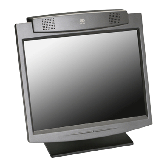
Overview Chapter 1: 19429 Introduction The NCR 5964 is a 12.1-inch SVGA (800X600) Liquid Crystal Display with Touch Screen. -
Page 12: Model Number
Chapter 1: Overview Model Number The 5964's twelve-digit model number is located on its serial number label. The model number identifies the 5964 features. The twelve-digit model number is defined in the following illustration. 5964 20 90 90 Class Number... -
Page 13: Compatibility
Chapter 1: Overview Compatibility The 5964 is designed as an optional input/output device for the following workstations: • NCR 7452/7453-4000 Retail Workstation • NCR RealPOS 7456 Retail Terminal Standard Features The 5964 contains a 12.1-inch active matrix (TFT) color LCD Touch Screen: •... -
Page 14: Wedge Controller
The controller logically connects these devices in series with a standard PC keyboard. The retail workstation or PC interprets the data flow as keyboard input. For more information on the Wedge, refer to the NCR Wedge Software User’s Guide, BD20-1368-B. The 5964 includes support for a decoded RS-232 scanner. -
Page 15: Optional Features
2-Track JIS MSR This kit (5964-K012) includes an integrated 2-track JIS MSR head. No MSR Kit This kit (5964-K010) is a filler plate to cover the hole in the 5964 cabinet with no MSR is installed. Peripheral Tray Mount for 5964 This kit is used to attach the 5964-2000 integrated model to the workstation. -
Page 16: Integrated 2 X 20 Customer Display
Chapter 1: Overview Integrated 2 x 20 Customer Display The 5964 can include an optional integrated customer display, which is a 5972 VFD or LCD Customer Display with multiple mounting options. 19452... -
Page 17: Chapter 2: Site Preparation
Site Preparation Chapter 2: Physical Environment The physical environments required for the 5964 LCD Display are listed in this section. Operating Range Condition Range Temperature 5° to 45°C Relative Humidity 10% to 90% (Non-condensing) Atmospheric Pressure 3000 meters (max.) Storage Range... -
Page 18: Electrical Environment
Chapter 2: Site Preparation Electrical Environment Voltage Tolerance Current (Typical) Current (Max) ±10% +12 V Supply 1000 mA 1500 mA 12.1”LCD Voltage +5V External ±5% 250 mA Keyboard Voltage ±5% +5V External 250 mA Wedge Scanner Voltage Power Consumption (Touch Head) Typical Maximum 12 W... -
Page 19: Dimensions
Chapter 2: Site Preparation Dimensions (348 mm) 13.7 in. (297 mm) 11.7 in. (252 mm) 9.9 in. 19555 Tilt/Swivel Dimensions Hinge Tilt Angle 87.6 Swivel Angle Swivel Angle 88.0 88.0 20305... -
Page 20: 5964 W/Customer Display
Chapter 2: Site Preparation 5964 w/Customer Display 16.6 in. (42.2mm) 12.9 in. 13.7 in. (328 mm) (348 mm) 19557... -
Page 21: 12.1-Inch Lcd Display
Chapter 2: Site Preparation 12.1-inch LCD Display LCD Panel The 12.1-inch LCD panel is mounted behind the front plastic bezel of the enclosure. At least one TFT (active matrix) is supported. Only 3.3-volt LCD panels are supported. A field replaceable fuse for safety protects power to the panel. -
Page 22: Lcd Backlight Inverter Module
Chapter 2: Site Preparation LCD Backlight Inverter Module Power for the LCD backlight is supplied by an inverter circuit, which is integrated on the LCD controller board in the 12.1” LCD. While the inverter can be set to various levels of brightness, the 12.1” LCD can only turn the backlight to maximum brightness or a lower brightness for dark environments. -
Page 23: Chapter 3: Installation
Caution: Use a grounding strap when installing this feature. Installing the 5964 The 5964 is fully assembled at the factory. This section describes: • Serial number locations •... -
Page 24: Serial Number Location
(card-swipe) on the unit chassis. By tilting the LCD display and removing the Cable Cover you can see the other label. Connector Panel Access The 5964 has 4 cable connectors. They are located on the bottom of the Touch LCD assembly. Tilt display to access the cable connectors. 19453... -
Page 25: Connector Panel Location
Keyboard RS-232 19454 5964 Cables Connecting to a POS Please refer to your terminal’s Hardware User’s Guide for installation instructions and to the Site Preparation Guide for the proper hole sizes to cut when routing this cable within a modular configuration. -
Page 26: Cable Routing
The cables are routed down through the Mount Assembly 19455 Mounting Options The 5964 LCD Display is configured with a Table-Top Mount that can be installed on a flat horizontal surface. It is also configured with an integrated mount that attaches to the workstation. -
Page 27: Installing An Integrated Customer Display (5972-F040)
Chapter 3: Installation Installing an Integrated Customer Display (5972-F040) The Integrated 5972 2 x 20 Display is mounted to the 5964 using feature 5972-F040. Integrated Display Swivel Telescoping Post Telescoping Post Adapter Customer Display Post Base Screw (4) 20050... - Page 28 Chapter 3: Installation 1. Secure the Customer Display Post Base to the Table Top Mount with screws (4). Customer Display Table Top Mount Post Base 19456...
- Page 29 Chapter 3: Installation 2. Route the cable (display connector end) up through the mount components as shown below. This is a tight fit and the connector has to be angled in order to make it though the openings. Use care to not damage the wires.
- Page 30 Chapter 3: Installation 4. Connect the cable to the display module. a) Remove the Integrated Display Bracket (2 screws). b) Connect the cable to the 2 x 20 VFD Assembly. c) Replace the Integrated Display Bracket. Phillips PH Screw Integrated Display Bracket 2 x 20 VFD Assembly (4-24 x 0.625) 20101...
- Page 31 Chapter 3: Installation 5. Install the Customer Display Assembly onto the post. 19452 6. Connect the Customer Display Cable to the host terminal. This varies, depending on the terminal type. • 7456: Connect to a Powered RS-232 connector • 7452/53: Connect to a RS-232 connector and connect the Pigtail cable to an Aux Power Connector...
-
Page 32: Powering Up
3-10 Chapter 3: Installation Powering Up This section describes powering up the workstation and the initial checkout procedures after all hardware has been installed. Note: No unit setup is required at installation unless the configuration must be changed from factory defaults. The Wedge Support Disk (LPIN G370-0701-0000) permits configuration of the operational parameters in the Wedge. -
Page 33: Calibrating The Touch Screen
Chapter 3: Installation 3-11 Calibrating the Touch Screen Be sure to observe for the following Touch Screen calibration guidelines: • Calibrate the touch screen as part of the installation process. • Recalibrate the touch screen when the system is installed at its final location. - Page 34 3-12 Chapter 3: Installation 3. The following screen is displayed with two targets. Place your finger on the target that has a finger icon pointing towards it and hold it until the statement Touch Enable is displayed over the finger icon.
- Page 35 Chapter 3: Installation 3-13 5. The MicroTouch Calibration dialog box then appears. Do not touch the screen until this dialog box is no longer displayed. 6. From the Calibration Complete screen, select Done. 7. Select to exit the MicroTouch program. Close 8.
-
Page 36: Calibration Using Microcal (Dos)
3-14 Chapter 3: Installation Calibration Using Microcal (DOS) The calibration program looks at where your finger is when you lift it off the screen, not where you touch it. Therefore, calibrate the screen as follows: 1. Touch the screen near the calibration target. 2. -
Page 37: Summary
Chapter 3: Installation 3-15 Summary If there is a Touch Screen calibration issue during or after installation, take the following actions in the order listed: 1. Recalibrate. 2. If recalibration is unsuccessful after two attempts, then run the Noise check to change the frequency. 3. -
Page 38: Screen Saving Feature
The display has a time-out function that causes the display to go blank after several minutes of inactivity. The screen saving feature is controlled by NCR platform software that comes as part of the standard terminal operating system image. This functionality is also available by installing the Retail Platform Software for Windows LPIN (D370-0548). -
Page 39: Chapter 4: Programming
Programming Chapter 4: Device Interfaces Caution: When performing touch screen calibration on the 5964 LCD under Windows 95, note that if the terminal is shut down improperly the calibration may be lost. To avoid this situation, verify the terminal is properly shut down after calibrating the touch screen. To shut down... -
Page 40: Wedge Controller Interface
This bar code label is scanned and the resulting data block is programmed into an on board non-volatile EEPROM on the 5964 LCD Display Main Board during the manufacturing process. This provides the touch controller with course calibration data prior to initial system power-up. - Page 41 Chapter 4: Programming • 9600 baud • No parity • 7 data bits • 2 stop bits • Format hex • Autobaud enabled For better compatibility with the MicroTouch DOS and Windows drivers and mouse emulator it is desirable to select the following communications parameters: •...
-
Page 42: Msr Interface
MSR head plugs into the main board. All decode circuitry resides on the main board. The decoder is based on the Trigantor chip currently used in NCR Retail products. The keyboard should not be used while a card is being swiped in the MSR. -
Page 43: Chapter 5: Service And Repair
Failure to do so could damage the equipment. Caution: Before servicing the 5964 Touch LCD, power down the terminal or PC and disconnect the terminal AC power cord. Disconnect the cables from the PC or workstation to the Touch Screen. -
Page 44: Problem Isolation Procedures
Chapter 5: Service and Repair Problem Isolation Procedures NCR offers both on-site and mail-in service for the NCR 5964. Before calling for service or mailing in your unit for repair, step through the problem isolation procedures below to make sure the Touch Screen module is in need of repair. - Page 45 Chapter 5: Service and Repair Symptom Probable Cause Solution temperatures below 5° C. Unit in direct sunlight For best display quality, keep the unit out of direct sunlight or other bright light sources. Lines in LCD Internal LCD harness Re-seat the LCD harness at the Touch Screen Display loose control board and LCD ends.
- Page 46 Touch Screen sensor Ensure that the Touch Screen sensor harness is working harness loose securely fastened to the 5964 control board. Incorrect RS-232 The default setting for the Touch Screen is settings in the Touch 9600 N 7 2. Ensure that the application and Screen Controller or Touch Screen settings match.
-
Page 47: Servicing The Touch Screen Module
Chapter 5: Service and Repair Servicing the Touch Screen Module This section provides detailed instructions on how to completely disassemble the NCR 5964 LCD Display. Touch Screen Cleaning Procedures 1. Spray an ammonia-based glass cleaner on a soft cloth and gently wipe the touch screen clean. -
Page 48: Disassembly Procedures
Chapter 5: Service and Repair Disassembly Procedures This section explains how to disassemble the 5964 LCD Display for servicing. Caution: Power down the terminal before disassembling the unit. Removing the Back Cover 1. Tilt the display to access the cable connectors. - Page 49 Chapter 5: Service and Repair 4. Remove the screws (4) that secure the Back Cover of the 5964. Screws 19458...
- Page 50 Chapter 5: Service and Repair 5. Lift the Back Cover and unplug the MSR Cable from the Controller Board. Remove the Back Cover MSR Cable 19459...
-
Page 51: Removing The 5964 Wedge Touch Controller Board
Chapter 5: Service and Repair Removing the 5964 Wedge Touch Controller Board 1. Disconnect the following cables from the Controller Board. • Flex Cable • Backlight Cable • Touchscreen Cable Flex Cable Touchscreen Backlight 19460 2. Remove the 4 hex screws from the cable connector row. - Page 52 5-10 Chapter 5: Service and Repair 3. Remove the 5 screws that secure the PC board to the panel. Screws Screws 19462 4. Remove the board...
-
Page 53: Removing The Lcd
Chapter 5: Service and Repair 5-11 Removing the LCD 1. Remove the 2 screws that secure the LCD Bracket Assembly. Remove the assembly. Screws 19469 2. Loosen the 2 screws on one end of the LCD Bracket, but do not remove them. -
Page 54: Replacing The Backlight
5-12 Chapter 5: Service and Repair 4. Remove the LCD, being careful to not damage the Backlight Cable. 19464 Replacing the Backlight After you remove the LCD from the frame, you can replace the Backlight. 1. Remove the screw that secures the Backlight. 2. -
Page 55: Replacing The Touchscreen
Chapter 5: Service and Repair 5-13 Replacing the Touchscreen Make sure that you place the new Touchscreen in properly. The side with the plastic coating should be situated on the outside. To view this properly, turn the Touchscreen to one side and verify which side has the plastic. -
Page 56: Removing The Msr
5-14 Chapter 5: Service and Repair Removing the MSR 1. Remove the MSR screws (2). Screws 19466 2. Disconnect the MSR Cable from the PC board. Caution: Use care replacing the cable. 19467... -
Page 57: Spare Parts List
Spare Parts List Part Part Number 5-Wire resistive Touchscreen (0.11-inch thick) 497-0423210 Samsung 12.1-Inch TFT LCD (Hi-Bright) 006-8604312 5964 Wedge Touch Controller PC Board 497-0423512 Y-Cable - CHAMP Connector to DVI and RS-232 1416-C739-0010 497-0423567 1416-C739-0040 497-0423568 LCD Ribbon Cable... -
Page 58: External Keyboard Connector
5-16 Chapter 5: Service and Repair External Keyboard Connector The external keyboard connector is a PS/2-style, 6-pin, mini-DIN connector. The following table lists the function of each pin. Symbol Description DATA Keyboard Data Unused GROUND Ground 5V Power CLOCK Keyboard Clock Unused... -
Page 59: Index
Index —C— —P— Cable Routing, 3-4 Panel OFF/ON Sequence, 4-4 Compatibility, 1-3 Physical Environment, 2-1 Connector Panel Access, 3-2 Problem Isolation Procedures, 5-2 Programming, 4-1 —D— —R— Dimensions, 2-3 Removing the MSR, 5-14 —E— —S— Electrical Environment, 2-2 External Keyboard Connector, 5-16 Screen Saving Feature, 3-16 Serial Number Location, 3-2 —F—...