Furuno 1833 Installation Manual
Marine radar
Hide thumbs
Also See for 1833:
- Operator's manual (248 pages) ,
- Operator's manual (252 pages) ,
- Quick start manual (7 pages)
Table of Contents
Advertisement
Advertisement
Table of Contents

Related Manuals for Furuno 1833


Summary of Contents for Furuno 1833
- Page 1 MARINE RADAR MODEL1833/1933/1943...
- Page 2 Your Local Agent/Dealer Your Local Agent/Dealer 9-52 Ashihara-cho, 9-52 Ashihara-cho, Nishinomiya, Japan Nishinomiya, Japan Telephone : Telephone : 0798-65-2111 0798-65-2111 Telefax : Telefax : 0798-65-4200 0798-65-4200 FIRST EDITION : FIRST EDITION : APR. APR. 2001 2001 All rights reserved. All rights reserved. Printed in Japan Printed in Japan : APR.
-
Page 3: Safety Instructions
This is possible - Ask Serious injury or death can result if some- your FURUNO representative or dealer to one falls from the radar mast. provide this feature. Turn off the power at the mains switch- Distance to board before beginning the installation. -
Page 4: Table Of Contents
SYSTEM CONFIGURATIONS.................. v 1. MOUNTING ......................1-1 1.1 Installation of Display Unit....................... 1-1 1.2 Mounting of Antenna Unit for MODEL 1833 ................... 1-4 1.3 Mounting of Antenna Unit for MODEL 1933/1943 ................1-11 2. WIRING ......................... 2-1 2.1 Standard Wiring ..........................2-1 2.2 External Buzzer (OP03-136, option) Connection................ -
Page 5: Equipment Lists
EQUIPMENT LISTS Standard supply Name Type Code No. Remarks Display unit RDP-127 RSB-0071-057 MODEL 1833 XN10A-RSB-0070-064 MODEL1933, 24 rpm Antenna unit XN10A-RSB-0073-064 MODEL1933, 48 rpm XN12A-RSB-0070-059 MODEL1943, 24 rpm XN12A-RSB-0073-059 MODEL1943, 48 rpm Remote Remote controller, vinyl case, RMC-100 000-089-885... - Page 6 Optional supply Name Type Code No. Remarks Rectifier PR-62 000-013-484 For MODEL1833, 100 VAC 000-013-485 For MODEL1833, 110 VAC 000-013-486 For MODEL1833, 220 VAC 000-013-487 For MODEL1833, 230 VAC RU-3423 000-030-443 For MODEL1933/1943 External buzzer OP03-136 000-086-443 MJ-A6SPF0014-010 000-144-421 For NavNet, 1 m MJ-A6SPF0014-050 000-144-422 For NavNet, 5 m...
-
Page 7: System Configurations
SYSTEM CONFIGURATIONS The MARINE RADAR MODEL 1833/1933/1943 has IP address to communicate with the “NavNet” products located within the network, based on the TCP/IP protocol through Ethernet 10Base-T. A NavNet system may consist of one, two, three or four display unit and one ETR. - Page 8 Antenna Unit GP-310B/320B Radar data Plotter data Sounder data Network Transducer ETR-6/10N Figure 2 (a) NavNet system, three-unit connection Antenna Unit GP-310B/320B Radar data Plotter data Figure 2 (b) NavNet system, two-unit connection...
-
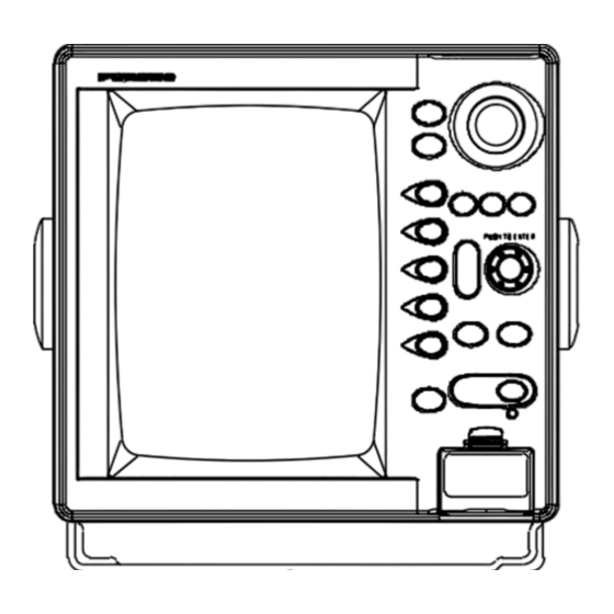
Page 9: Mounting
MOUNTING Installation of Display Unit The display unit can be installed on a tabletop, on the overhead or flush mounted in a console or panel. Tabletop, overhead mounting method When selecting a mounting location for the display unit keep the following in mind: •... - Page 10 1.1.1 Mounting procedure Tabletop, overhead mounting Follow the procedure below to mount the display unit on a tabletop or the overhead. 1. Fix the hanger by four tapping screw. 2. Screw knob bolts in display unit, set it to hanger, and tighten knob bolts. 3.
- Page 11 1. Prepare a cutout in the mounting location by using the template sheet supplied as the installation material. 2. Fix the display unit by four washer head screws M4x20. Refer to the outline drawing at back of this manual. 264+0.5 Washer head screws 258+1 4-R2.25...
-
Page 12: Mounting Of Antenna Unit For Model1833
Mounting of Antenna Unit for MODEL1833 1.2.1 Mounting considerations When selecting a mounting location for the antenna unit keep in mind the following points. • Install the antenna unit on the hardtop, radar arch or on a mast on an appropriate platform. - Page 13 1.2.2 Mounting antenna unit of MODEL 1833 1. Open the antenna unit packing box carefully. 2. Unbolt the four bolts at the base of the radome to remove the radome cover. Radome cover Antenna unit The mounting surface must be parallel with the waterline and provided with five holes whose dimensions are shown in the outline drawing attached at the end of this manual.
- Page 14 Antenna base plate Effective Gasket thread length Radome 25 mm 5 - 10 mm Flat washer Spring Platform washer M10 x 25 Apply silicone sealant. Hex bolt How to fasten the radome base to the mounting platform Wiring and final preparation 4.
- Page 15 to one of the screws of the cable clamping plate 9-pin connector: to J801 on MD-9208 4-pin connector: to J802 on MD-9208 13-pin connector: to J611 on IF-9214A Signal cable, antenna unit side J802 J801 MD-9208 Cable entry PTU-9335 J611 IF-9214 RF unit...
- Page 16 10. Attach the EMC core supplied as shown below. J801 J802 MD9208 J805 J804 J806 J803 Cable entrance Cable Motor clamping plate EMC core E04SS251512 (Above cable clamping plate) J613 PTU-9335 IF9214 IF9214A J611 How to attach EMC core 11. Fix the shield cover. Do not pinch the cable. 12.
- Page 17 1.2.3 Mounting the optional mounting bracket A mounting bracket for fastening the antenna unit for MODEL1833 to a mast on a sailboat is optionally available. Mounting bracket 1 Type: OP03-92 Code No.: 008-445-070 Table 1-1 Mounting bracket contents Type Code No. Hex.
- Page 18 Support plate (A) Assembling the mounting bracket (B) Fastening antenna to mounting bracket How to assemble and mount the optional mounting bracket 1-10...
-
Page 19: Mounting Of Antenna Unit For Model1933/1943
Mounting of Antenna Unit for MODEL1933/1943 1.3.1 Mounting considerations • The antenna unit is generally installed either on top of the wheelhouse or on the radar mast on a suitable platform. Locate the antenna unit where there is a good all-round view. Any obstruction will cause shadow and blind sectors. - Page 20 1.3.2 Mounting antenna unit of MODEL 1933/1943 Referring to the outline drawing at the back of this manual, drill five holes in the mounting platform: four holes of 15 mm diameter for fixing the antenna unit and one hole of 25-30 mm diameter for the signal cable.
- Page 21 Mounting of antenna unit The antenna unit can be mounted using the fixing holes on the outside (200 x 200 mm) or inside (140 x 150 mm) the antenna unit. Outside fixing holes Use the hex head bolt (supplied) to mount the antenna unit as below. 1.
- Page 22 Hex bolt Seal washer Flat washer Spring washer Fixing the antenna unit chassis 4. Pass flat washers (M12, supplied), spring washers (M12, supplied) and nuts (M12, supplied) onto hex bolts. Fasten by tightening nuts. Do not fasten by tightening the hex bolts;...
- Page 23 Hex bolt Flat washer Ground Flat washer terminal Spring washer Hex nut Silicone GROUND sealant POINT Hex nut Ground Spring washer wire Flat washer Hex nut Weld here. GROUND TERMINAL Silicone sealant Ground wire antenna unit How to coat ground point and ground terminal with silicone sealant 1-15...
- Page 24 Fixing holes inside antenna unit This method requires removal of the RF unit in the antenna unit to access inside fixing holes. Use hex head bolts, flat washers, spring washers and nuts (local supply) to mount the antenna unit, confirming length of bolts. 1.
-
Page 25: Wiring
2. WIRING Standard Wiring All wiring are terminated at the rear of the display unit. Power cable connector Connect power Optional cable cable here. (Remote display and external monitor) Signal cable (to antenna unit) Ground terminal Connect ground wire between Drain hole here and ship's ground. - Page 26 Power cable Connect the power cable to the POWER connector. Signal cable connection (from the antenna unit) Connect the signal cable to SIGNAL connector. Ground terminal Connect the ground wire (local supply, IV-2sq) between the ground terminal and ship’s ground. DATA1 to DATA3 Other equipments can be connected here as shown below.
-
Page 27: External Buzzer (Op03-136, Option) Connection
1742/1762/1722C/ HUB (used when more 1732C/1742C/1762C/1752C than two NavNet units GD1700/1700C/1900C ETR-6/10N are connected.) 1833/1933/1943/ 1833C/1933C/1943C/1953C External Buzzer (OP03-136, option) Connection The optional external buzzer provides a louder alert when the guard alarm is violated. External buzzer Type: OP03-136 Code no.:... -
Page 28: How To Connect With Pc
How to Connect with PC When connecting with the personal computer, prepare the optional cable assy MJ-A7SPF0007-050 and D-sub 9 pins plug (local supply), and connect them as follows. SHIELD BLUE WHITE D-SUB 9PIN MJ-A7SPF0007-050 WHITE BLUE RD_A RD_B +12V SHIELD EXT BUZZ short... -
Page 29: Adjustment
3. ADJUSTMENT How to Access to Installation Menu You should do the set up for the equipment through the installation menu when installation has been finished. To access to the installation menu, follow the steps in below. 1. Press the [POWER/BRILL] key with touch-and-release action while pressing the [MENU] key down. -
Page 30: Network Setup Menu
NETWORK SETUP Menu To communicate with other NavNet equipment, this setting should be done. 1. Open the INSTALL SETUP menu. 2. Press the NETWORK SETUP soft key. NETWORK IP ADDRESS SETUP 172.031.003.002 HOST NAME EDIT RADAR________ RADAR SOURCE RADAR________ CHART SOURCE ______________ ______________ ______________... - Page 31 Contents of Network setup menu Item Description Default Setting IP ADDRESS This address is assigned at the factory. Change the address (last three digits; 001 to 254) when like models are connected directly or through the hub. Do this change before connecting the 172.031.003.002 equipment to the other equipment or hub to distinguish.
-
Page 32: Radar Setup Menu
3.3 RADAR SETUP Menu After the network setup, do the following in order to adjust the radar. Open the INSTALL SETUP menu, and then press the RADAR SETUP soft key to display the RADAR SETUP menu. When the message of “RADAR DOES NOT TRANSMIT. TRANSMIT RADAR?”... - Page 33 3.3.2 TUNING Initialize the tuning as follows. 1. Transmit the radar 2. Open the RADAR SETUP menu, and then select TUNING by the trackball or [ENTER] knob. 3. Press the EDIT soft key or [ENTER] knob to show the setting window. TUNING Tuning setup menu 4.
- Page 34 Press the EDIT key or [ENTER] key to show the setting window. TIMING ADJUST Timing adjust setting menu Select ON and press the [ENTER] knob or ENTER soft key to show the radar display. RETURN PUSH ENTER KNOB AFTER ADJUSTING SWEEP TIMING. Timing adjustment setting display 6.
- Page 35 3.3.5 HEADING ADJUST You have mounted the antenna unit facing straight ahead in the direction of the bow. Therefore, a small but conspicuous target dead ahead visually should appear on the heading line (zero degrees). In practice, you will probably observe some small error on the display because of the difficulty in achieving accurate initial positioning of the antenna unit.
- Page 36 3.3.6 M. B. (Main Bang) SUPPRESSION Main bang (black hole), which appears at the display center on short ranges, can suppressed as follows. 1. Open the RADAR SETUP menu and select M.B. SUPPRESSION by trackball. 2. Press the EDIT soft key or [ENTER] knob to show the setting window. 3.
-
Page 37: Stc Curve
3.3.8 STC CURVE The default STC curve can be maintained in most cases. If necessary the STC curve can be changed as follows: 1. Open the RADAR SETUP menu and select STC CURVE. 2. Press the EDIT soft key or [ENTER] knob to show the setting window. RETURN STC CURVE NARROW... -
Page 38: Checking Magnetron Heater Voltage
1. Open the antenna unit. 2. Turn on the power. Do not transmit the radar. 3. Connect a multimeter, set to 10VDC range, appropriate position on the PTU (1833) or RTB (1933/1943) Board in the antenna unit. Refer to the table in below. -
Page 39: Navigation Data Source
2. Select POSITION SOURCE and press the [EDIT] key or [ENTER] knob to show the position source window. 3. Select FURUNO BB GPS, GP, LC or ALL as appropriate and press the [ENTER] knob or ENTER soft key. FURUNO BB GPS: GPS Receiver GP-310B/320B... - Page 40 6. Press the SYSTEM SETUP soft key followed by PORT SETUP and GPS/NMEA PORT soft keys. 7. Select FURUNO GPS SENSOR, and press the [ENTER] knob or EDIT soft key to show FURUNO GPS SENSOR window. 8. Select YES and press the [ENTER] knob or ENTER soft key.
- Page 41 Contents of GPS sensor settings menu Item Description Settings Default Setting Local Time Offset -13:30 to +13:30 hr 0 hr (no offset) Allows the user to use local time (instead of UTC time). Enter time difference between local time and UTC time. Use the + <...
- Page 42 Contents of GPS sensor settings menu (con’t.) Item Description Settings Default Setting Longitude Offset As above but for longitude. Use the W < - 9.999’E – 9.999’W 0.0’ (no offset) - > E soft key to switch coordinate. Disable Satellite Every GPS satellite is broadcasting None abnormal satellite number (s) in its...
-
Page 43: Setting Up Data Ports
3. Press the GPS/NMEA PORT for DATA1 port or PC/NMEA EXT, BUZZ PORT for DATA3 port soft key as appropriate. One of the following displays appear depending on your selection. NMEA FURUNO GPS SENSOR NMEA OUTPUT FORMAT PORT PORT NMEA 0183 VER2.0... - Page 44 8. Press the RETURN soft key. 9. Press the [MENU] key to quit. Contents of DATA 1 PORT menus Item Description Settings Default Setting FURUNO GPS Selects whether the GPS Receiver Yes, No Sensor GP-310B/320B is connected to the DATA1 port or not. Output Format Selects NMEA output version of the NMEA0183 Ver.
-
Page 45: Remote Controller Setting
Remote Controller Setting A remote controller can be set exclusively for use with a specific display unit, in the case of multiple NavNet display units. Set the remote controller mode desired on the menu and attach appropriate label (supplied with accessories) to the remote controller and display unit. - Page 46 This page is intentionally left blank.
-
Page 47: Options
4. OPTIONS ARP Kit ARP-11 Necessary parts Name: ARP kit Type: ARP-11 Code no.: 008-523-050 Table 4-1 ARP-11 contents Name Type Code No. ARP Board 18P9013 008-521-830 Pan head screw M3x6 C2700W 000-881-403 000-801-850 Spacer SQ15 000-801-779 Spring washer M3 C5191W 000-864-204 1. - Page 48 4. Fasten four spacers and washers (supplied with option kit) to the locations shown below. 5. Mate P109 on the ARP Board (option) to J109 on the SPU Board. 6. Fix the ARP Board and SPU Board with four pan head screws and spring washers (supplied with option kit).
-
Page 49: Connection Of External Monitor/Remote Display
Connection of External Monitor/Remote Display The above units can be connected to the MODEL1833/1933/1943 by using the hole at the rear of the display unit. Remove the connector cover to use this hole. After connecting, cover the hole with soft putty to seal the hole. VGA monitor CAUTION Even though the display... - Page 50 24P Connector Nut Rubber grommet Cut a "X" in the (Small) 4 pcs. rubber grommet. Connector Nut (Large) 1 pc. 5 pcs. Use this pan head screw to fix the ground wire of the RGB output cable. Remove connector cover. Cable tie J106 How to connect the RGB output cable...
- Page 51 4.2.2 Connecting remote display The FURUNO Display unit FMD-811, MODEL1832 or GD-280/380, etc. can be connected to the NavNet display as remote display. To interconnect them, use a cable attached with or set as option for the remote display. 1. Unscrew six connecter nuts at the rear of the display unit.
- Page 52 This page is intentionally left blank.
- Page 67 空中線部 ANTENNA UNIT 指 示 部 DISPLAY UNIT MJ-B24LPF0005,10/15/20/30m,φ11 RDP-127 RSB-0070/0073 (17C+2C2V,MAX.30m) FUSE MJ-A3SPF0018 J106(XH10P) 7A:24V J8211(VH9P) (03S9368-0),5m,φ10 MJ-A3SRMD SIG-R キ(太) YEL[B] +12V J1351 15A:12V (VV-S 2.0x2C) 12-24 VDC シロ WHT +12V クロ(太) BLK[B] クロ BLK SIG-G アカ(太) RED[B] DPYC-1.5 *1 100/110/220/230VAC -12V シロ(太)...