Furuno 1835 Operator's Manual
Hide thumbs
Also See for 1835:
- Operator's manual (130 pages) ,
- Installation manual (49 pages) ,
- Quick manual (3 pages)

Related Manuals for Furuno 1835


Summary of Contents for Furuno 1835
- Page 1 OPERATOR'S MANUAL MARINE RADAR MODEL 1835 MODEL 1935 MODEL 1945 Model www.furuno.com...
- Page 2 The paper used in this manual is elemental chlorine free. ・FURUNO Authorized Distributor/Dealer 9-52 Ashihara-cho, Nishinomiya, 662-8580, JAPAN A : FEB 2009 Printed in Japan All rights reserved. D1 : NOV . 25, 2015 Pub. No. OME-35790-D1 ( ETMI ) MODEL1835/1935/1945...
- Page 3 How to discard a used battery Some FURUNO products have a battery(ies). To see if your product has a battery(ies), see the chapter on Maintenance. Follow the instructions below if a battery(ies) is used. In the European Union The crossed-out trash can symbol indicates that all types of batteries must not be discarded in standard trash, or at a trash site.
- Page 4 XN12A-RSB-0070-059, XN12A-RSB-0073-059 Distance to Distance to Model 10 W/m point 100 W/m point 1835 Worst case 2.2 m Worst case 0.1 m 1935 Worst case 2.2 m Worst case 0.2 m Worst case 2.4 m 1945 Worst case 0.2 m...
- Page 5 SAFETY INSTRUCTIONS WARNING WARNING ELECTRICAL SHOCK HAZARD Use the correct fuse. Do not open the equipment. A wrong fuse can damage the equipment and cause fire. Only qualified persons can work inside the equipment. Keep heater away from the equipment. Turn off the power before you service the antenna unit.
- Page 6 Transistor) LCD displays 99.999% Do not remove any label. If a label is missing or of its picture elements. damaged, contact a FURUNO agent or dealer The remaining 0.001% may drop about replacement. out or light, however this is an DISPLAY UNIT inherent property of the LCD;...
-
Page 7: Table Of Contents
TABLE OF CONTENTS FOREWORD ........................ix SYSTEM CONFIGURATION ..................xii DESCRIPTION OF OPERATION ................1-1 1.1 Controls ........................1-1 1.2 How to Turn the Radar On/Off and Transmit..............1-2 1.3 Display Indications......................1-3 1.4 How to Adjust Display Brilliance, Panel Dimmer ............1-4 1.5 Menu Description......................1-4 1.6 Tuning.........................1-6 1.7 Display Modes ......................1-7 1.7.1... - Page 8 TABLE OF CONTENTS 1.24.7 How to restart, stop the trails ............... 1-33 1.24.8 Narrow trails ....................1-34 1.24.9 Your ship trail ....................1-34 1.25 How to Send the Target Position and Enter the Origin Mark ........1-34 1.26 How to Hide the Heading Line Temporarily ............. 1-35 1.27 Presentation Brilliance .....................
- Page 9 TABLE OF CONTENTS ARPA OPERATION ....................3-1 3.1 Precautions for Use ....................3-1 3.2 Controls for Use with ARPA ..................3-1 3.3 ARPA Display On/Off ....................3-2 3.4 How to Acquire and Track the Targets ...............3-2 3.4.1 Manual acquisition..................3-2 3.4.2 Automatic acquisition ..................3-3 3.5 How to Stop the Tracking of ARPA Target ..............3-3 3.5.1 How to stop the tracking of selected targets ..........3-3 3.5.2...
- Page 10 TABLE OF CONTENTS 6.8 ARPA Test ....................... 6-10 6.9 GPS Test........................6-11 APPENDIX 1 MENU TREE ..................AP-1 APPENDIX 2 GEODETIC CHART LIST ..............AP-5 SPECIFICATIONS .....................SP-1 INDEX.......................... IN-1 viii...
-
Page 11: Foreword
Marine Radar Congratulations on your choice of the FURUNO MODEL1835/MODEL1935/MODEL1945 Marine Radar. We are confident you will see why the FURUNO name has become synonymous with quality and reliability. Since 1948, FURUNO Electric Company has enjoyed an enviable reputation for innovative and dependable marine electronics equipment. - Page 12 FOREWORD Radar Type and Function Availability This radar series is available in four types: [River], [Sea], [IEC] and [Russian-River], and function availability depends on type. The table below shows type and function availability. [River]: For river, [Sea]: For sea, [IEC]: IEC compliant radar, [Russian-River]: For Russian river Type and function availability Item Type...
- Page 13 FOREWORD Item Type River Russian-River Pulselength • 2NM/4KM/2SM: MP • 2NM/4KM/ • 4NM/8KM/4SM: LP 2SM: SP or • 4NM/8KM/ 4SM: MP or LP The rule for the Non-IEC system IEC system numbering of ARPA targets Marks temporary Heading line, all marks (EBL, VRM, Heading line, vector of your ship (with hidden by press- target alarm zone, etc.)
-
Page 14: System Configuration
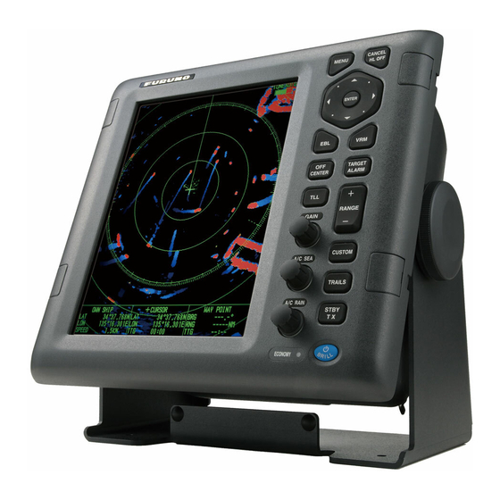
SYSTEM CONFIGURATION Basic configuration is shown below with solid line. MODEL 1945 MODEL 1935 MODEL 1835 Antenna unit Antenna unit Antenna unit XN12A-RSB-0070-059 XN10A-RSB-0070-064 RSB-0071-057 XN12A-RSB-0070-059A XN10A-RSB-0070-064A RSB-0071-057A XN12A-RSB-0073-059 XN10A-RSB-0073-064 XN10A-RSB-0073-064A XN12A-RSB-0073-059A Display unit RDP-152 Heading sensor CANCEL MENU HL OFF... -
Page 15: Description Of Operation
DESCRIPTION OF OPERATION Controls Display unit The display unit has 16 keys which have labels with their functions, three knob con- trols and a Cursorpad. When you correctly operate this equipment, the unit beeps one time. If your operation is wrong, the unit beeps three times. Control Description CANCEL... -
Page 16: How To Turn The Radar On/Off And Transmit
1. DESCRIPTION OF OPERATION How to Turn the Radar On/Off and Transmit Press the key to turn on the radar. To turn off the radar, press and hold down the key until the screen turns off. When you turn on the power, the initialization screen appears followed by the start-up screen. -
Page 17: Display Indications
1. DESCRIPTION OF OPERATION Display Indications Offcenter (M: Manual, A: Auto, C: Custom) Input source (shown when display Trail reference Heading unit functions as Trail time remote display) North marker 3 5 0 . 0 ° Range TRAIL(T) TUNEAUTO SLAVE H D G Tuning indicator 15 S... -
Page 18: How To Adjust Display Brilliance, Panel Dimmer
4. Press the CANCEL/HL OFF key to close the window. Menu Description This MODEL 1835 series has 15 menus and 6 sub menus. Below is the basic proce- dure for menu operation. 1. Press the MENU key to open the menu. - Page 19 1. DESCRIPTION OF OPERATION 2. Use the Cursorpad ( or ) to select a menu or a sub menu. The cursor (yellow) in the Menu column indicates the menu currently selected. The menu items in the right window change according to the menu selected. Menu description [Brill/Color]: Adjust the brilliance and color.
-
Page 20: Tuning
1. DESCRIPTION OF OPERATION Tuning In default, the radar receiver can be tuned automatically after turning the radar to TX. If you require fine tuning in manual, do the following: 1. Transmit the radar and select the maximum range with the RANGE key. 2. -
Page 21: Display Modes
1. DESCRIPTION OF OPERATION Display Modes This radar has the display modes shown below. All modes except head-up require a heading signal. The true motion mode additionally requires position data. Relative Motion (RM) • [Head Up] (H UP) • [Course Up] (C UP) •... -
Page 22: Description Of Display Modes
1. DESCRIPTION OF OPERATION the alarm message display. To stop the audio alarm, press any key. When the heading signal is restored, check the heading. To check the heading, press the F3 key. The numeric value is displayed at the heading indication when the heading signal is re- stored. -
Page 23: How To Select A Range Scale
1. DESCRIPTION OF OPERATION North marker True motion mode Heading line Your ship and other objects in motion move with their true courses and speed. All fixed tar- gets, like landmasses, appear as fixed echoes in ground stabilized TM. When your ship reaches a point that is 75% of the radius of the display, the position is reset. -
Page 24: How To Adjust The Gain (Sensitivity)
1. DESCRIPTION OF OPERATION How to Adjust the Gain (sensitivity) The gain functions to adjust the sensitivity of the receiver for the best reception. The gain can be adjusted automatically or manually. 1. Press the MENU key to open the menu. 2. -
Page 25: How To Reduce The Sea Clutter
1. DESCRIPTION OF OPERATION 1.10 How to Reduce the Sea Clutter The reflected echoes from the waves appear around your ship and have the name "sea clutter". The sea clutter extends according to the height of waves and antenna above the water. When the sea clutter hides the targets, use the A/C SEA control to reduce the clutter, either manually or automatically. -
Page 26: How To Reduce The Rain Clutter
1. DESCRIPTION OF OPERATION Sea clutter at A/C SEA control adjusted; screen center sea clutter reduced Sea clutter 2. Press the CANCEL/HL OFF key to close the window. 1.11 How to Reduce the Rain Clutter The reflections from the rain or snow appear on the screen. These reflections have the name "rain clutter". -
Page 27: Automatic Adjustments Of Sea And Rain Clutters
1. DESCRIPTION OF OPERATION Note: When you want to adjust the rain clutter finely in [Auto] mode, rotate the A/C RAIN knob. The confirmation message appears. If you select [Yes], the mode chang- es to [Manual] mode. Rotate the A/C RAIN knob to adjust the rain clutter. Are you sure to change to manual mode? Confirmation message Manual mode... -
Page 28: Cursor
1. DESCRIPTION OF OPERATION 1.13 Cursor The cursor functions to find the range and bearing (default function) to a target or the latitude and longitude position of a target. Use the Cursorpad to position the cursor and read the cursor data at the screen bottom. Cursor 110.1°... -
Page 29: Interference Rejector
1. DESCRIPTION OF OPERATION 3. Use the Cursorpad ( or ) to select [Cursor Position] and press the ENTER key. Cursor Position options 4. Use the Cursorpad ( or ) to select [Rng/Brg] or [Lat/Lon] then press the EN- TER key. (When the navigation data is displayed, cursor latitude and longitude po- sition cannot be displayed.) 5. -
Page 30: How To Measure The Range To A Target
1. DESCRIPTION OF OPERATION 1.15 How to Measure the Range to a Target You can measure the range to a target in three methods. You can use the fixed range rings, the cursor (if set to measure range and bearing), and the VRM (Variable Range Marker). -
Page 31: How To Measure The Range With A Vrm
1. DESCRIPTION OF OPERATION 1.15.2 How to measure the range with a VRM There are two VRMs, No. 1 and No. 2. The VRMs are dashed rings so that you can identify the rings from the fixed range rings. You can identify VRM 1 from VRM 2 by different lengths of dashes. -
Page 32: How To Measure The Bearing To A Target
1. DESCRIPTION OF OPERATION 3. Use the Cursorpad ( or ) to select [VRM Unit] and press the ENTER key. NM: 0.1 NM or above YD: Less than 0.1 NM VRM Unit options 4. Use the Cursorpad ( or ) to select the unit and press the ENTER key. 5. -
Page 33: Ebl Reference
1. DESCRIPTION OF OPERATION 1.16.2 EBL reference "R" (relative) follows the EBL indication if the bearing is relative to the heading of your ship. "T" (true) follows the EBL indication if the bearing is in reference to the north. You can select relative or true in the head-up and true view modes. -
Page 34: How To Select A Pulselength
1. DESCRIPTION OF OPERATION 7. Read the bearing and range indications at the bottom of the screen. EBL 2 EBL 1 Target B VRM 2 Target D VRM 1 Target A EBL origin Target C 4 5 . 0 ° R 0 . -
Page 35: Target Alarm
1. DESCRIPTION OF OPERATION 2. Use the Cursorpad ( or ) to select [Echo] and press the ENTER key. Echo menu 3. Use the Cursorpad ( or ) to select [Pulse Length] and press the ENTER key. Pulse Length options 4. -
Page 36: How To Set A Target Alarm Zone
1. DESCRIPTION OF OPERATION 1.19.1 How to set a target alarm zone The following procedure shows you how to set a target alarm zone. 1. Press the TARGET ALARM key to activate ALARM 1 or ALARM 2. Press the TARGET ALARM key to change the active ALARM between No. 1 and No. 2. The indication of the currently active ALARM is in a rectangle at the upper-right corner of the screen. -
Page 37: How To Select The Alarm Type
1. DESCRIPTION OF OPERATION 1.19.3 How to select the alarm type You can set the target alarm to activate against targets entering or exiting the alarm zone. “In” target alarm “Out” target alarm In and Out target alarms 1. Press the MENU key to open the menu. 2. -
Page 38: How To Deactivate A Target Alarm
1. DESCRIPTION OF OPERATION 2. Press the CANCEL/HL OFF key. The alarm indication now shows "ALM1(or 2)_ACK". To activate a sleeping target alarm zone, press the TARGET ALARM key to select the ALARM 1 or ALARM 2 and press the ENTER key. The alarm indication then changes to "ALM1(or 2)_IN(or OUT)". -
Page 39: How To Off-Center The Display
1. DESCRIPTION OF OPERATION 1.20 How to Off-center the Display You can off-center your ship position to expand the view field without selecting a larger range scale. The display can be off-centered manually, or automatically according to speed of the ship. Note: Off-centering is not available in the true motion mode. - Page 40 1. DESCRIPTION OF OPERATION Custom (Indication: "OFFCENT(C)") You can move your ship position to the position which you pre-set. Follow the proce- dure shown below to register the cursor position. 1. Press the OFF CENTER key several times until the off-center indication disap- pears.
-
Page 41: Zoom
1. DESCRIPTION OF OPERATION 1.21 Zoom The zoom function expands the length and width of a selected target as much as twice its normal size, in the zoom window. You select the target to zoom with the zoom cur- sor. The selected target is zoomed in the zoom window. ARPA and AIS symbols can be displayed in the zoom window, but are not zoomed. - Page 42 1. DESCRIPTION OF OPERATION Target zoom mode The ARPA or AIS target as below can be displayed in the zoom window: ARPA: The symbol is enlarged twice its normal size. AIS: The symbol is enclosed in a broken square. (The symbol is not enlarged.) The zoom cursor moves with the ARPA or AIS target.
-
Page 43: Echo Stretch
1. DESCRIPTION OF OPERATION 1.22 Echo Stretch The echo stretch feature enlarges the targets in the range and bearing directions to make the targets easier to see. This feature is available on any range. There are three levels of echo stretch, [1], [2] and [3]. [3] enlarges the targets the most. Note: The echo stretch magnifies the targets, sea and rain clutters, and radar interfer- ence. -
Page 44: Target Trails
1. DESCRIPTION OF OPERATION 4. Use the Cursorpad ( or ) to select an echo averaging option and press the EN- TER key. [Off]: Deactivate the echo average. [1]: Identify true targets from the sea clutter and reduce the brilliance of unstable echoes. -
Page 45: How To Start, Stop The Trails
1. DESCRIPTION OF OPERATION 1.24.2 How to start, stop the trails 1. Press the TRAILS key to start the trails and select the trail time. The selected time with the trail mode is shown at the upper-right corner as in the figure shown below. The available trail time with the TRAILS key changes according to trail times, which you turn on in section 1.24.1. -
Page 46: Trail Gradation
1. DESCRIPTION OF OPERATION 3. Use the Cursorpad ( or ) to select [Mode] and press the ENTER key. Mode options 4. Use the Cursorpad ( or ) to select [Relative] or [True] then press the ENTER key. 5. Press the MENU key to close the menu. 1.24.4 Trail gradation Trails can be shown in single or multiple gradation. -
Page 47: Trail Level
1. DESCRIPTION OF OPERATION 1.24.6 Trail level You can select which target strength to display. 1. Press the MENU key to open the menu. 2. Use the Cursorpad ( or ) to select [Target Trails] and press the ENTER key. 3. -
Page 48: Narrow Trails
1. DESCRIPTION OF OPERATION Note: If the newly selected range is less than or equal to 1/4 of the previous range, trails are erased. If the newly selected range is longer than the previous range, the previous trails are left to be displayed. 5. -
Page 49: How To Hide The Heading Line Temporarily
1. DESCRIPTION OF OPERATION TLL key mode You can select how to handle TLL position. 1. Press the MENU key to open the menu. 2. Use the Cursorpad ( or ) to select [Others] and press the ENTER key. 3. Use the Cursorpad ( or ) to select [TLL Key Mode] and press the ENTER key. TLL Key Mode options 4. -
Page 50: Custom Setup
1. DESCRIPTION OF OPERATION 1.28 Custom Setup 1.28.1 About custom setup When your navigating environment or task changes, you must adjust the radar. In- stead of changing radar settings case by case, you can assign the CUSTOM key to provide best settings for common conditions. There are three default custom setups for the internal computer of the radar (see the table on the next page). -
Page 51: How To Set Custom Setups
1. DESCRIPTION OF OPERATION Menu item Available settings See section [Pulse Length] [Short] or [Long], you can select on 1.5, 1.6, 3.0 and 3.2 nm 1.18 ranges. [Echo Stretch] [Off], [1], [2], [3] 1.22 [Echo Average] [Off], [1], [2], [Auto] 1.23 [Noise Rejector] [Off], [On]... -
Page 52: How To Program Function Keys (F1, F2 And F3 Keys)
1. DESCRIPTION OF OPERATION 1.29 How to Program Function Keys (F1, F2 and F3 keys) You can program function keys (F1, F2 and F3) to provide one-touch access to a re- quired function. Function key operation To activate a function, press function key, F1, F2 or F3. Press same key to change the setting. -
Page 53: Noise Rejector
1. DESCRIPTION OF OPERATION 1.30 Noise Rejector White noise can appear on the screen as random "marks". You can reduce this noise as follows: 1. Press the MENU key to open the menu. 2. Use the Cursorpad ( or ) to select [Echo] and press the ENTER key. 3. -
Page 54: How To Reduce Second-Trace Echoes
1. DESCRIPTION OF OPERATION 1.32 How to Reduce Second-trace Echoes Echoes from very distant targets can appear as false echoes (second-trace echoes) on the screen. The second-trace echo occurs when the return echo is received one transmission cycle later, or after a next transmission of radar pulse. TX repetition Second-trace echo... -
Page 55: Color Selections
1. DESCRIPTION OF OPERATION Do the following to activate the Watchman: 1. Press the MENU key to open the menu. 2. Use the Cursorpad ( or ) to select [Alarm] and press the ENTER key. 3. Use the Cursorpad ( or ) to select [Watchman] and press the ENTER key. Watchman options 4. -
Page 56: Custom Colors
1. DESCRIPTION OF OPERATION 1.34.2 Custom colors The custom color design lets you select preferred echo, background, characters, range rings and marks colors. Select [Custom] in the [Display Color] menu item (see section 1.34.1) to use the user selected echo, background, characters, range rings and marks colors. -
Page 57: Navigation Data
1. DESCRIPTION OF OPERATION 1.35 Navigation Data 1.35.1 Navigation data during standby The navigation data is shown in standby when [STBY Display] on the [Display] menu is set to [Nav]. Appropriate sensors are required to display the data. Standby indication Speed Trip Depth... -
Page 58: Dynamic Range
1. DESCRIPTION OF OPERATION To show or hide the navigation data at the bottom of the screen, do the following: 1. Press the MENU key to open the menu. 2. Use the Cursorpad ( or ) to select [Display] and press the ENTER key. 3. -
Page 59: Characteristics Curve
1. DESCRIPTION OF OPERATION 1.37 Characteristics Curve You can change the characteristics curve to reduce unwanted weak echoes (sea re- flections, etc.). Select [1], [2] or [3] depending on conditions when unwanted weak echoes hide wanted targets. 1. Press the MENU key to open the menu. 2. -
Page 60: Waypoint Marker
1. DESCRIPTION OF OPERATION 1.38 Waypoint Marker The waypoint marker shows the location of the destination waypoint set on a naviga- tion plotter. The heading signal or course data are required. You can turn on/off the waypoint marker as follows: Waypoint marker Waypoint marker... - Page 61 1. DESCRIPTION OF OPERATION 3. Use the Cursorpad ( or ) to select [Alarm Status] and press the ENTER key. TRIGGER HEADING BEARING GYRO VIDEO POSITION NMEA_HDG IN OUT IN OUT COLLISION LOST PROXIMITY COLLISION PROXIMITY TX ANT CH1 CH2 CH70 FAIL MKD EPFS L/L SOG COG HDG ROT OVER_TEMP Alarm Status display...
-
Page 62: Echo Area
1. DESCRIPTION OF OPERATION Alarm category Meaning AIS SYSTEM* TX stopped or TX error Antenna VSWR problem TDM2 RX1 board problem TDM2 RX2 board problem CH70 RX channel 70 problem FAIL System failure Minimum input device lost EPFS Navigator (GPS, etc.) problem Position data lost Speed data lost Course data lost... -
Page 63: Initial Sub Menu
1. DESCRIPTION OF OPERATION 3. Use the Cursorpad ( or ) to select [Echo Area] and press the ENTER key. Echo Area options 4. Use the Cursorpad ( or ) to select [Normal] or [Full Screen] then press the EN- TER key. - Page 64 1. DESCRIPTION OF OPERATION NM (nautical miles) KM (kilometers) SM (statute miles) Available ranges for MODEL 1835 NM (nautical miles) KM (kilometers) SM (statute miles) Available ranges for MODEL 1935 NM (nautical miles) KM (kilometers) SM (statute miles) Available ranges for MODEL 1945...
-
Page 65: Units Sub Menu
1. DESCRIPTION OF OPERATION [Wind Direction]: Wind direction is shown as [Apparent] or [True]. [NMEA Port 1]: Set the baud rate of the equipment connected to Port 1 ([Auto], [4800], or [38400] (bps)). [Auto] provides automatic detection of baud rate from 4800, 9600, 19200 or 38400 (bps). -
Page 66: Sector Blank
1. DESCRIPTION OF OPERATION 1.43 Sector Blank You must prevent the transmission in some areas to protect passengers and crew from microwave radiation. Also, if the reflections of echoes from the mast appear on the screen, you must prevent the transmission in that area. You can set two sectors. 1. -
Page 67: Other Menu Items
1. DESCRIPTION OF OPERATION Area of no End bearing transmission Start bearing of sector of sector Sector blank 1.44 Other Menu Items This section describes the menu items not previously described. 1.44.1 Menu items on the [Brill/Color] menu [View Position]: You can select the angle from where you see the screen. View Position options [Menu Transparency]: You can select the degree of transparency of the menu win- dow so the menu window does not hide the echo display. - Page 68 1. DESCRIPTION OF OPERATION Echo Color Mode options [Custom Echo Color]: You can customize the echo color with the following two meth- ods. This function is not available in the [IEC] or [Russian-River] mode. Custom Echo Color setting window Method 1: 1) Select the echo rank to change on the [Rank] (setting range: 1 - 31). 2) Set the RGB values for selected echo rank on the [Red], [Green] and [Blue] (setting range: 0 - 63).
-
Page 69: Menu Items On The [Display] Menu
1. DESCRIPTION OF OPERATION 1.44.2 Menu items on the [Display] menu [Base Text Display]: You can select on/off for the text indications of the following items on the display. The settings on this function are used when you set [Echo Area] to [Full Screen] on the [Display] menu. -
Page 70: Menu Items On The [Echo] Menu
1. DESCRIPTION OF OPERATION 1.44.3 Menu items on the [Echo] menu [Color Erase]: Erase the lower echo color whose level is set here. Set a large value to display only the stronger echoes. Color Erase setting window 1.45 Remote Display You can use this radar as a remote display when you set [Input Source] to [Slave] on the [Installation] sub menu. - Page 71 1. DESCRIPTION OF OPERATION Items unavailable with Function key F1, F2 and F3 • [Pulse Length] ([Echo] menu) • [2nd Echo Rejector] ([Echo] menu) • [Watchman] ([Alarm] menu) • [Tuning Mode] ([Tuning] menu) Total TX time indication The total TX time (TX TIME XXXXXX.XH) does not appear on the diagnostic test or on the Normal standby display.
- Page 72 1. DESCRIPTION OF OPERATION This page is intentionally left blank. 1-58...
-
Page 73: Description Of Radar
The minimum range depends on the pulselength, antenna height, and signal process- ing (like main bang suppression and digital quantization). Use a shorter range scale as far as it gives favorable definition or clarity of picture. This MODEL 1835 series meets the requirements of IEC 62252 5.14.1 (Class A). -
Page 74: Radar Resolution
2. DESCRIPTION OF RADAR 2.1.2 Radar resolution The bearing resolution and range resolution are important in radar resolution. Bearing resolution The bearing resolution is the ability of the radar to display the echoes received from two targets at the same range as the separate echoes. The bearing resolution is pro- portional to the antenna length and the wavelength. -
Page 75: Bearing Accuracy
2. DESCRIPTION OF RADAR 2.1.3 Bearing accuracy One of the most important features of the radar is how accurately the bearing of a tar- get can be measured. The accuracy of bearing measurement depends on the narrow- ness of the radar beam. The bearing is taken relative to the heading of the ship. Correct adjustment of the heading line at installation is important to get accurate bear- ings. -
Page 76: Sidelobe Echoes
2. DESCRIPTION OF RADAR 2.2.2 Sidelobe echoes When the radar pulse is transmitted, some radiation escapes on each side of the beam, called "sidelobes". If a target is where a target can be detected by the sidelobes as well as the mainlobe, the side echoes can be shown on both sides of the true echo at the same range. -
Page 77: Shadow Sector
2. DESCRIPTION OF RADAR 2.2.4 Shadow sector Funnels, stacks, masts, or derricks near the antenna interrupt the radar beam, and a non-detecting sector can occur. Targets can not be detected within this sector. Wharf and its echo Radar position Wharf and its echo Radar position Shadow sector Shadow sector occurs... -
Page 78: Sart (Search And Rescue Transponder)
2. DESCRIPTION OF RADAR SART (Search and Rescue Transponder) 2.3.1 SART description When any X-band radar reaches within a range of approximately 8 nm, a Search and Rescue Transponder (SART) sends a response to the radar signal. The transmitter signal of response is 12-sweeps signal between 9,500 MHz to 9,200 MHz. The time of slow sweep signal is 7.5 μs and the time of fast sweep signal is 0.4 μs. -
Page 79: General Remarks On Receiving Sart
2. DESCRIPTION OF RADAR 2.3.2 General remarks on receiving SART SART range errors When the SART is at a range greater than approximately 1 nm, the first dot is dis- played at 0.64 nm beyond the true position of the SART. When the range closes so that the fast sweep responses are seen also, the first range echoes are displayed at 150 m beyond the true position. -
Page 80: Racon
2. DESCRIPTION OF RADAR RACON A RACON is a radar beacon which emits radar-receivable signals in the radar frequen- cy spectrum (X- or S-band). There are several signal formats; in general, the RACON signal appears on the radar screen as a rectangular echo originating at a point just beyond the position of the radar beacon. -
Page 81: Arpa Operation
ARPA OPERATION The Automatic Radar Plotter ARP-11 (option) manually or automatically acquires and tracks ten targets. Once a target is acquired automatically or manually, a target is au- tomatically tracked within 0.1 to 16 nm. Precautions for Use CAUTION CAUTION CAUTION CAUTION Do not depend on one navigation device... -
Page 82: Arpa Display On/Off
3. ARPA OPERATION ARPA Display On/Off You can turn the ARPA display on or off. The system continuously tracks ARPA tar- gets regardless of this setting. 1. Press the MENU key to open the menu. 2. Use the Cursorpad ( or ) to select [ARPA] and press the ENTER key. 3. -
Page 83: Automatic Acquisition
3. ARPA OPERATION 3.4.2 Automatic acquisition When you set an automatic acquisition area, the ARPA can acquire up to five targets automatically. The automatic acquisition area is 2.0 to 2.5 nm in range and ±45° on either side of the heading line in bearing. -
Page 84: Vector Attributes
3. ARPA OPERATION 3. Use the Cursorpad ( or ) to select [All Cancel] and press the ENTER key. All Cancel options 4. Use the Cursorpad () to select [Yes] and press the ENTER key. All symbols are erased from the screen and the long beep sounds. 5. -
Page 85: Vector Of Your Ship
3. ARPA OPERATION 3. Use the Cursorpad ( or ) to select [Vector Time] and press the ENTER key. Vector Time setting window 4. Use the Cursorpad ( or ) to select time and press the ENTER key. 5. Use the Cursorpad ( or ) to select [Vector Reference] and press the ENTER key. -
Page 86: History Display (Target Past Position)
3. ARPA OPERATION Vector of your ship Cursor Data box History Display (target past position) This radar can display time-spaced dots (maximum ten dots) that mark the past posi- tions of any tracked ARPA target. You can evaluate actions of a target by the spacing between dots. -
Page 87: Arpa Target Data
3. ARPA OPERATION 6. Use the Cursorpad ( or ) to select [History Interval] and press the ENTER key. History Interval options 7. Use the Cursorpad ( or ) to select the time interval and press the ENTER key. 8. Press the MENU key to close the menu. ARPA Target Data You can show the data for a tracked ARPA target in the data box at the bottom of the screen. -
Page 88: Cpa/Tcpa Alarm
3. ARPA OPERATION CPA/TCPA Alarm Set CPA (Closest Point of Approach) alarm range and TCPA (predicted Time to CPA) alarm time to alert you to targets that can be on a collision course. When CPA and TCPA of any ARPA target become less than the preset CPA and TCPA alarm settings, the audio alarm sounds. -
Page 89: Proximity Alarm
3. ARPA OPERATION 5. Use the Cursorpad ( or ) to select [TCPA] and press the ENTER key. TCPA options 6. Use the Cursorpad ( or ) to select TCPA and press the ENTER key. 7. Press the MENU key to close the menu. 3.10 Proximity Alarm The proximity alarm alerts you when an ARPA target is within the range you set. -
Page 90: Lost Target
3. ARPA OPERATION 3.11 Lost Target When the system detects a lost target, the audio alarm sounds and the alarm mes- sage "LOST" appears. The target symbol becomes a flashing square like the following illustration. When the system detects the target again, the target symbol becomes a normal symbol. -
Page 91: Ais Operation
AIS OPERATION Connected to the FURUNO AIS Transponders FA-150, FA-100, FA-50 or the AIS Re- ceiver FA-30, the MODEL 1835 series can show the name, position and other naviga- tion data of the nearest 100 AIS transponder-equipped ships. This radar accepts position data fixed by WGS-84 geodetic datum. Set the datum to WGS-84 on the GPS navigator connected to this radar. -
Page 92: Ais Symbols
4. AIS OPERATION 3. Use the Cursorpad ( or ) to select [Display] and press the ENTER key. AIS-Display options 4. Use the Cursorpad ( or ) to select [Off] or [On] then press the ENTER key. 5. Press the MENU key to close the menu. AIS Symbols When the AIS is turned on, AIS targets are displayed with AIS symbol as below. -
Page 93: Ais Target Data
4. AIS OPERATION When there are many activated targets on the screen, you can not easily distinguish the activated targets from the radar images or ARPA targets. You can sleep an acti- vated target for easy view of radar images. Sleeping target To activate a target: Put the cursor on the target and press the ENTER key. -
Page 94: How To Sort Targets
You can set the AIS system to show only those AIS targets within the range you set. The setting range is 0.1-36 nm for MODEL 1835, 0.1-48 nm for MODEL 1935, 0.1-64 nm for MODEL 1945. Actual range depends on the AIS Transponder. If the target sort- ing method is selected to [Range], the target data within the range set here is trans- mitted to this radar. -
Page 95: How To Display The Targets Within A Specific Sector
4. AIS OPERATION How to Display the Targets within a Specific Sec- You can display AIS targets only within a specific sector. If the target sorting method is selected to [Sector], the target data within the sector set here is transmitted to this radar. -
Page 96: Vector Attributes
4. AIS OPERATION 4. Use the Cursorpad ( or ) to select the number of targets to display and press the ENTER key. 5. Press the MENU key to close the menu. 4.10 Vector Attributes 4.10.1 What is a vector? A vector is a line extending from a tracked target. -
Page 97: History Display (Target Past Position)
4. AIS OPERATION 4.11 History Display (target past position) This radar can display time-spaced dots (maximum ten dots) that marks the past po- sitions of any tracked AIS target. You can evaluate actions of a target by the spacing between dots. Below are examples of dot spacing and target movement. (a) Ship turning (b) Ship running (d) Ship increased... -
Page 98: Cpa/Tcpa Alarm
4. AIS OPERATION 4.12 CPA/TCPA Alarm Set CPA (Closest Point of Approach) alarm range and TCPA (predicted Time to CPA) alarm time to alert you to targets that can be on a collision course. When CPA and TCPA of any AIS target (including a sleeping target) become less than the preset CPA and TCPA alarm settings, the audio alarm sounds. -
Page 99: Proximity Alarm
4. AIS OPERATION 4.13 Proximity Alarm The proximity alarm alerts you when an AIS target is within the range you set. The au- dio alarm sounds and the alarm message "PROXIMITY" appears. The target symbol changes to a dangerous target symbol (red) and flashes with its vector. Press any key to stop the audio alarm and flashing. -
Page 100: Symbol Color
4. AIS OPERATION 4. Use the Cursorpad () to select [Yes] and press the ENTER key. All lost targets symbols are erased from the screen and the long beep sounds. 5. Press the MENU key to close the menu. 4.15 Symbol Color You can select the AIS symbol color among Green, Red (unavailable in the [IEC] or [Russian-River] purpose), Blue, White or Black. -
Page 101: Gps Operation
GPS OPERATION If the FURUNO GPS Navigator GP-320B is connected to this radar, you can set GP- 320B from this radar. Navigator Mode 1. Press the MENU key to open the menu. 2. Use the Cursorpad ( or ) to select [GPS] and press the ENTER key. -
Page 102: Waas Setup
5. GPS OPERATION WAAS Setup Geostationary satellites, the type used with WAAS, provide more accurate position data when compared to GPS. These satellites can be tracked automatically or manu- ally. Auto tracking automatically searches for the best geostationary satellite from your current position. -
Page 103: Satellite Monitor
5. GPS OPERATION Satellite Monitor The Satellite Monitor provides the information about GPS and WAAS satellites. See your GPS navigator's owner's manual for detailed information. 1. Press the MENU key to open the menu. 2. Use the Cursorpad ( or ) to select [GPS] and press the ENTER key. 3. -
Page 104: Cold Start
5. GPS OPERATION Cold Start Cold start, which clears the Almanac from the GPS receiver, can be necessary in the following conditions: • If you have turned off the power of the GPS receiver for a long time. • The ship has moved far away from the previous fixing position (e.g., more than 500 km). -
Page 105: Maintenance, Troubleshooting
MAINTENANCE, TROUBLE- SHOOTING This chapter has information about maintenance and troubleshooting that the user can follow to care for the equipment. WARNING ELECTRICAL SHOCK HAZARD Do not open the equipment. Only qualified personnel can work inside the equipment. Turn off the power before you service the antenna unit. -
Page 106: Preventive Maintenance
6. MAINTENANCE, TROUBLESHOOTING Preventive Maintenance Regular maintenance helps keep your equipment in good condition and prevents fu- ture problems. Check the items shown in the table below to help keep your equipment in good condition for years to come. Maintenance Interval Item Check point... -
Page 107: Magnetron Life
When the life of the magnetron is reached, the targets do not appear on the display. If long-range performance appears to have decreased, contact a FURUNO agent or dealer about replacement of the magnetron. The magnetron changes with the type of antenna unit. -
Page 108: Simple Troubleshooting
6. MAINTENANCE, TROUBLESHOOTING Simple Troubleshooting This section provides simple troubleshooting procedures which the user can follow to restore normal operation. If you cannot restore normal operation, do not check inside the unit. Have a qualified technician check the equipment. Simple troubleshooting Problem Remedy You cannot turn on the power. -
Page 109: Advanced-Level Troubleshooting
6. MAINTENANCE, TROUBLESHOOTING Advanced-level Troubleshooting This section describes how to cure hardware and software troubles which the qualified service persons must do. Advanced-level troubleshooting Probable cause orcheck Problem Remedy points Power cannot be 1) Mains voltage/polarity 1) Correct the wiring and input turned on. - Page 110 6. MAINTENANCE, TROUBLESHOOTING Probable cause orcheck Problem Remedy points Radar is correctly 1) [2nd Echo Rejector] is [On] 1) Turn off the [2nd Echo Re- tuned but sensitivi- jector], from the [Echo] ty is poor. menu. 2) Dirt on radiator face 2) Clean radiator.
-
Page 111: Diagnostic Test
6. MAINTENANCE, TROUBLESHOOTING Diagnostic Test The diagnostic test checks the system for correct operation. This test is for use by ser- vice technicians, but the user can do this test to provide the service technician with information. 1. Press the MENU key to open the menu. 2. - Page 112 6. MAINTENANCE, TROUBLESHOOTING • HEADING PULSE, BEARING PULSE: The results of the pulse input are dis- played as OK or NG. When [Antenna Rotation] is set to [Stop], or [Watchman] is set to [Off] in the STBY mode, this test is skipped and "- -" is shown for both heading and bearing.
-
Page 113: Lcd Test
6. MAINTENANCE, TROUBLESHOOTING LCD Test 1. Press the MENU key to open the menu. 2. Use the Cursorpad ( or ) to select [Tests] and press the ENTER key. 3. Use the Cursorpad ( or ) to select [LCD Pattern] and press the ENTER key. MENU MENU MENU... -
Page 114: Arpa Test
6. MAINTENANCE, TROUBLESHOOTING ARPA Test If the optional ARPA board is installed, its program number and test results (OK or NG) are shown on the screen. [ARPA Test] menu item is inoperative with no ARPA board. The radar must be transmitting to test ARPA function. 1. -
Page 115: Gps Test
6. MAINTENANCE, TROUBLESHOOTING GPS Test You can check the FURUNO GPS receiver GP-320B interfaced with this radar for cor- rect operation as follows: 1. Press the MENU key to open the menu. 2. Use the Cursorpad ( or ) to select [GPS] and press the ENTER key. - Page 116 6. MAINTENANCE, TROUBLESHOOTING This page is intentionally left blank. 6-12...
-
Page 117: Appendix 1 Menu Tree
APPENDIX 1 MENU TREE MENU key Brill/Color Echo Brill (1 - 8) Rings Brill (Off, 1, 2, 3, 4) Mark Brill (1, 2, 3, 4) HL Brill (1, 2, 3, 4) Character Brill (1, 2, 3, 4) View Position (Left, Left-Center, Center, Right-Center, Right) Display Color (Day, Night, Twilight, Custom) Echo Color (Yellow, Green, Orange, Multi) Background Color (Black, DK Blue, Blue, White) - Page 118 APPENDIX 1 MENU TREE (Continued from previous page) Custom1 (Off, On) Custom 1 Copy Gain Mode (Auto, Manual) Manual Gain (0 - 100) Sea Mode (Auto, Manual) Auto Sea (Coastal, Advanced) Manual Sea (0 - 100) Rain Mode (Auto, Manual) Auto Rain (Calm, Moderate, Rough) Manual Rain (0 - 100) A/C Auto (Off, On)
- Page 119 Color (Green, Red, Blue, White, Black) Number of Targets (10 - 100) Sort By (Range, Sector, CPA, TCPA) Range (0.1NM - 36.0NM*) *: 36.0NM for MODEL 1835 Sector Start (0° - 359°) 48.0NM for MODEL 1935 Sector End (0° - 359°) 64.0NM for MODEL 1945...
- Page 120 APPENDIX 1 MENU TREE (Continued from previous page) System Key Beep (Off, On) Initial Offcenter Speed (1kn - 99kn) Compass Type (Magnetic, True) Range Preset Wind Direction (Apparent, True) NMEA Port 1 (Auto, 4800bps, 38400bps) NMEA Port 2 (Auto, 4800bps, 38400bps) NMEA Mixing Out (Off, On) Self Test Tests...
-
Page 121: Appendix 2 Geodetic Chart List
APPENDIX 2 GEODETIC CHART LIST 001: WGS84 091: NORTH AMERICAN 1927BH : Bahamas (excl. San Salvador Is.) 002: WGS72 092: NORTH AMERICAN 1927SS : Bahamas, San Salvador Is. Mean Value (Japan, Korea & Okinawa) 003: TOKYO 093: NORTH AMERICAN 1927CN : Canada (incl. - Page 122 APPENDIX 2 GEODETIC CHART LIST : Tanzania : Con Son Is. (Vietnam) 221: INDIAN 1960 176: ARS-B : Thailand : Ascension Is. 222: INDIAN 1975 177: ASCENSION IS. 1958 Indonesia : Mean Value (Florida & Bahama Is.) 223: INDONESIAN 1974 178: CAPE CANAVERAL 224: CO-ORDINATE SYSTEM 1937 OF ESTONIA : Estonia : Easter Is.
-
Page 123: Specifications
3 to 64 Range discrimination 25 m Minimum range 25 m Bearing resolution MODEL 1835: 4°, MODEL 1935: 2.4°, MODEL 1945: 1.9° Bearing accuracy ±1° Range ring accuracy 0.9% of range in use or 8 m, whichever is greater ANTENNA UNIT... - Page 124 Relative wind speed 100 kn for 24 rpm/ 70 kn for 48 rpm TRANSCEIVER MODULE (CONTAINED IN ANTENNA UNIT) Radiation type Frequency 9410 MHz±30MHz Peak output power MODEL 1835/ MODEL 1935 4 kW MODEL 1945 6 kW Duplexer Circulator with diode limiter Modulator switching...
- Page 125 FURUNO MODEL 1835 series INTERFACE Heading signal AD-10 format or NMEA0183 NMEA 2 ports, NMEA0183 Ver-1.5/2.0/3.0 Remote display/ Ext. buzzer 1 port (option) 1 port, USB2.0 for maintenance Input data sentences ALR, BWC, BWR, DBT, DPT, DTM, GGA, GLL, GNS, GSA, GSV,...
- Page 126 This page is intentionally left blank.
-
Page 127: Index
INDEX head-up ........... 1-8 north-up ........... 1-8 A/C RAIN control........1-12 true motion ..........1-9 A/C SEA control ........1-11 true view ..........1-9 Dynamic range ........1-44 activating targets ........4-2 controls for ..........4-1 display on/off ........... 4-1 display range ........... - Page 128 INDEX Test ARPA .............6-10 Navigation data diagnostic ..........6-7 at screen bottom ........1-43 GPS............6-11 stand-by ..........1-43 LCD ............6-9 Noise rejector ...........1-39 TLL key ............1-34 North-up mode ...........1-8 TRAILS key ..........1-31 Troubleshooting OFF CENTER key ........1-25 advanced-level .........6-5 Off-centering the display ......1-25 simple............6-4 True motion mode ........1-9 POWER/BRILL key ......