Table of Contents
Advertisement
Quick Links
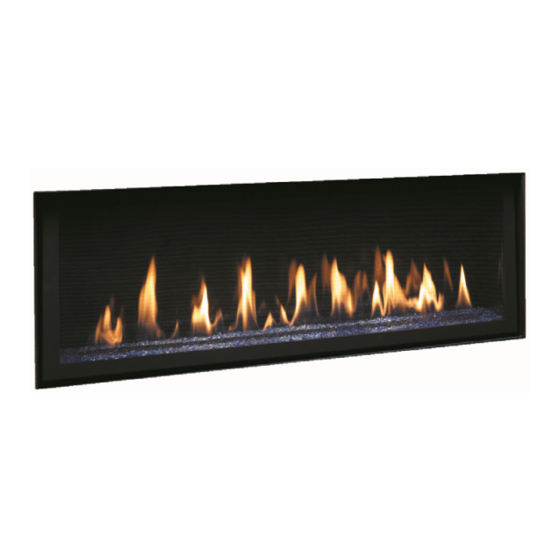
GreenSmart™ 2 Fireplace
WARNING:
If the information in these instructions is not followed exactly, a fire or explosion may
result causing property damage, personal injury or loss of life.
DO NOT PLACE ARTICLES ON OR AGAINST THIS APPLIANCE.
DO NOT USE OR STORE FLAMMABLE MATERIALS NEAR THIS APPLIANCE.
DO NOT SPRAY AEROSOLS IN THE VICINITY OF THIS APPLIANCE WHILE IT IS IN OPERATION.
DO NOT MODIFY THIS APPLIANCE.
-
Do not store or use gasoline or other flammable vapors and liquids in the vicinity of this or any other
appliance.
WHAT TO DO IF YOU SMELL GAS
• Do not try to light any appliance.
• Do not touch any electrical switch; do not use any phone in your building.
• Immediately call gas supplier from a neighbor's phone. Follow the gas supplier's instructions.
• If you cannot reach your gas supplier, call the fire department.
-
Installation and service must be performed by a qualified installer, service agency or the gas supplier.
This appliance may be installed in an aftermarket
permanently located, manufactured home (USA only)
or mobile home, where not prohibited by local codes.
This appliance is only for use with the type(s) of gas
indicated on the rating plate. A conversion kit is
supplied with the appliance.
Owner's Manual
Copyright 2014, T.I.
6015 HO
Operation
Maintenance
$10.00
100-01371
Listed by
AS 4553-2008 GMK 10166
IAPMO-R&T OCEANA
Dragon Wholesaling Pty. Ltd.
Unit 4, 16 Lexington Drive
Bella Vista NSW 2153
4131210
Australia
Advertisement
Table of Contents

Related Manuals for Lopi 6015 HO


Summary of Contents for Lopi 6015 HO
- Page 1 6015 HO GreenSmart™ 2 Fireplace Operation Maintenance Listed by AS 4553-2008 GMK 10166 IAPMO-R&T OCEANA WARNING: If the information in these instructions is not followed exactly, a fire or explosion may result causing property damage, personal injury or loss of life.
-
Page 2: Introduction
Introduction Introduction We welcome you as a new owner of a 6015 HO gas fireplace. This manual details operation and maintenance of this fireplace. Please familiarize yourself with the Owner's Manual before operating your heater and save the manual for future reference. -
Page 3: Table Of Contents
Heating Specifications Natural Gas Propane Approximate Heating Capacity (in square meters)* Up to 260 Up to 260 Maximum BTU Input Per Hour (MJ) 59.1 59.1 Heating capacity will vary with floor plan, insulation, and outside temperature. © Travis Industries 4131220 100-01371... - Page 4 Immediately call a qualified vicinity of this heater. service technician to inspect the appliance and to replace any part of the control system and any gas control that has been under water. © Travis Industries 4131220 100-01371...
- Page 5 If any component becomes damaged, replace with Travis Industries components. Children and adults should be Travis Industries, Inc. grants alerted to the hazards of high no warranty, implied or stated, surface temperature and should for the installation or...
-
Page 6: Before You Begin
The transmitter and IFC are radio frequency devices. Placing the transmitter in or near metal may severely reduce the signal range. Turn off the main gas supply during appliance installation or maintenance or in case of remote control malfunction. © Travis Industries 4131220 100-01371... -
Page 7: Remote Set-Up
PRG (Program) button for 10 seconds. The pilot will start to spark repeatedly, signifying all system memory has been cleared. The system will return to its original configuration a remote will need to be synchronized; and the system will operate in Continuous Pilot mode. © Travis Industries 4131220 100-01371... -
Page 8: Starting The Heater For The First Time
(i.e.: the IFC “remembers” the last setting). If you wish to adjust the mode settings use the transmitter mode button to adjust the settings. The thermostat and burner on/off operating functions will not work on the transmitter. © Travis Industries 4131220 100-01371... -
Page 9: Continuous/Intermittent Pilot Switch
IPI/CPI. NOTE: This icon appears when the appliance is in CPI mode. Press the "UP" button Press the "DOWN" button to activate CPI mode. to activate IPI mode. Figure 3 © Travis Industries 4131220 100-01371... -
Page 10: Remote Operation
NOTE: When the batteries start to get low, the IFC will beep twice whenever a button is pressed. When the batteries are nearly depleted, the IFC will no longer beep. See “IFC Batteries” on page 13). © Travis Industries 4131220... -
Page 11: Manual On-Off / Smart Thermostat / Standard Thermostat
Use the up or appear here. down buttons to adjust the target temperature. Figure 8 NOTE: If the transmitter batteries go dead while in thermostat setting (standard or smart), the appliance will shut off after approximately 24 hours. © Travis Industries 4131220 100-01371... -
Page 12: Mode Controls (Flame, Blower, Light)
When in Manual mode the blower will remain on, even if the burner is turned off and the heater cools. Either manually turn the blower off, or turn off the heater by pressing the On/Off button. © Travis Industries 4131220... -
Page 13: Travis Industries
Install four new AA alkaline batteries into the battery box when this occurs (see “Battery Installation” on page 14). In applications where the appliance is required to provide heat, we recommend replacing the batteries before each heating season. © Travis Industries 4131220 100-01371... -
Page 14: Battery Replacement
Figure 15 Power Outages The remote will work if household current (AC power) is disconnected. The batteries inside the battery box will continue to power the heater but the accent light and blower will not operate. © Travis Industries 4131220 100-01371... -
Page 15: Child-Proof Feature
This appliance has several areas that reach high temperatures. Dust or other particles on these areas may burn and create an odor. This is normal during startup. You may notice the smell is more acute if the appliance was left idle for a long period. © Travis Industries 4131220 100-01371... -
Page 16: Yearly Service Procedure
Monitor blower operation. 8. Remove any debris or vegetation near the vent termination. Contact your dealer if any sooting or deterioration is found near the vent termination. The venting system should be examined by a qualified agency. © Travis Industries 4131220 100-01371... -
Page 17: Accent Light Replacement
Replace the halogen bulbs with the following bulbs: 35 Watt 120 Volt T4 Halogen Bulb (G6.35 Base) NOTE: Take care to not touch the bulbs with your fingers – use foam packing or a paper towel to handle the bulbs, © Travis Industries 4131220 100-01371... -
Page 18: Glass Frame Removal And Installation
(1/4” wrench). The tool is accessed after removing the screen. NOTE: Replace the tool in this location after use. Remove the concealment cover and place aside. It has two holes that aid in removal. © Travis Industries 4131220 100-01371... - Page 19 3. Use the glass tool to unlatch the glass frame. Remove the glass frame. The glass frame is held in place with four tabs inserted into four slots at the bottom of the firebox opening. © Travis Industries 4131220 100-01371...
-
Page 20: Crushed Glass Installation
Disperse the crushed glass evenly along the glass tray. Make sure the two air channels are free of crushed glass. Use the glass frame tool (or screwdriver) to clear this area. Make sure the glass is only 1 layer deep on the burner. © Travis Industries 4131220 100-01371... -
Page 21: Glass Cleaning
To clean the inside of the glass, simply remove the glass frame, place it on a non-scratching surface, and clean the surface. WARNING: do not operate the fireplace without the glass frame in place. © Travis Industries 4131220 100-01371... -
Page 22: Troubleshooting Table
Replace the fuse. See fuse location below. Do Not Work Location of fuses The two 3 amp fuses are on the front left of the fireplace, under the concealment cover (see page 18). Fan Fuse Lights Fuse © Travis Industries 4131220 100-01371... -
Page 23: Wiring Diagram
On/Off) Replacement Parts List Caution: Use only Travis Industries replacement parts. Do not use substitute materials. Warning: Do not operate appliance with the glass front removed, cracked, or broken. Replacement of the glass should be done by a licensed or qualified service person. -
Page 24: Conditions & Exclusions
Dragon Wholesaling Pty. Ltd. Unit 4, 16 Lexington Drive Bella Vista NSW 2153 Australia. Dragon Wholesaling warrants this gas appliance (appliance is defined as the equipment manufactured by Travis Industries, Inc.) to be defect-free in material and workmanship to the original purchaser from the date of purchase as follows: Check with your dealer in advance for any costs to you when arranging a warranty call. - Page 25 Limited 7 Year Warranty © Travis Industries 4131220 100-01371...
-
Page 26: Index
Starting the Heater for the First Time ....8 Important Information ......... 2 Troubleshooting Table ........22 Installation Warnings .......... 2 Wiring Diagram ..........23 Location of Controls ........... 8 Yearly Service Procedure ........ 16 © Travis Industries 4131220 100-01371...