Table of Contents
Advertisement
Quick Links
Download this manual
See also:
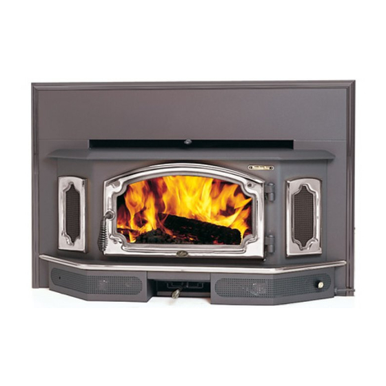
Owner's Manual
Advertisement
Table of Contents

Related Manuals for Lopi Freedom Bay Fireplace Insert


Summary of Contents for Lopi Freedom Bay Fireplace Insert
-
Page 1: Safety Notice
F r e e d o m B a y Fireplace Insert Owner's Manual Masonry Fireplace Insert Save these instructions for future reference SAFETY NOTICE:... - Page 2 Introduction Important Information Introduction Mail your Warranty Card Today, and Save Your Bill of Sale.
- Page 3 General Information Fireplace Insert Installation Preparation for Installation ... 7 Additional Accessories Needed for Installation ... 7 Installation Considerations ... 7 Operating Your Appliance Table of Contents Maintaining Your Appliance Remove Ash (if necessary)...21 Clean the Glass (if necessary) ...21 Door and Glass Inspection ...22 Creosote - Formation and Need for Removal ...2 Touch Up Paint ...23...
- Page 4 ASHES 36" Type Clay Liner...
- Page 5 Mobile Home This Manual...
- Page 6 Measure side clearances 6" Diameter Flue from the side of the insert. 20-1/4" Measure top clearances from the top plate. 43-3/4" Measure front clearances from the faceplate. 29-1/4" 5-5/8" 21-3/4" 15-3/4" 4-3/4" Fireplace Opening Faceplate Weight = 470 Lbs. Electrical Line (may be attached to the opposite side)
-
Page 8: Minimum Fireplace Size
Minimum Fireplace Size Height (front) Height (rear) Width (front) Width (rear) Depth Hearth Depth* Hearth Width Facing Width Facing Height with Mantel Shield Mantel Height with Mantel Shield * This is the distance the insert protrudes from the fireplace opening plus the required 16" of hearth extension. -
Page 9: Minimum Clearances
Measure side clearances from the side of the insert. Side Wall Measure front clearances from the faceplate. Minimum Clearances Sidewall to Insert Side Facing Top Facing with mantel shield Mantel to Insert with mantel shield Hearth (Front) Hearth (Side) Front of Insert Extension onto Hearth 15"... - Page 10 This distance is the hearth step-up. The leveling bolts should stick out this far from the Fireplace base of the insert. Hearth The leveling bolts go into the holes at the rear corners of the insert.
- Page 11 Damper See the dimensions to determine the location of the center of the Firebox flue. Block-Off Plate Template 2" Flanges Measurement "A" (for attaching the block-off plate) Measurement "B" See the dimensions to determine the location of the center of the flue. Measurement "C"...
- Page 12 Combustible Mantle Surround Panels See the section "Insert Placement Requirements" for minimum clearances and hearth required. Combustible Mantle Surround Panels See the section "Insert Placement Requirements" for minimum clearances and hearth required. Install a non-combustible cover plate to prevent water from entering the chimney Cap (prevents water from entering)
- Page 13 Flue Liner Combustible Mantle Surround Panels with insulation See the section "Insert Placement Requirements" for minimum clearances and hearth required. NOTE: It is recommended your chimney have a minimum 28 and a maximum of 144 square inch cross- sectional area to use a face seal connection, otherwise your chimney maynot have...
- Page 14 Rotate the door handle. 2 to 4 hours Swing the door open.
- Page 15 Use the included pull tool to operate the bypass rod Bypass Pulled Out Used for starting and re-loading Bypass Pushed In Used for normal operation...
- Page 17 Use the air control to change the burn rate. Low Burn High Burn (air control closed) (air control open) ASHES...
-
Page 18: Operating Your Appliance
Blower Operation Re-Loading the Stove Overnight Burn Normal Operating Sounds Operating Your Appliance Turn the dial all the way counter- clockwise until it clicks off. HIGH The high position Turn the dial is all the way all the way counter-clockwise, clockwise. - Page 19 Wood Cut wood to length and Store the wood off the ground in a chop into quarters. covered area. Allow for airflow around the wood to dry the wood. Air Flow Wood Leads Less More Heat Heat Leads More Smoke and Creostoe Air Flow Leads...
- Page 21 Allow the stove to fully cool. Apply glass cleaner or soapy water to the inside of the glass. Wipe with newspaper or a paper towel. For Stubborn Creosote: Dip newspaper or a paper towel in cool ashes and wipe it on the glass.
- Page 22 High-Temperature anti-sieze may be used on the door hinges to eliminate squeaks. If the glass is damaged, replace it - see “Replacement Parts” for details. Side View of Door Handle Door Cam Door Handle Washers Use a 9/16" Door Frame socket wrench to remove this nut.
- Page 23 Touch-Up P a i n t Use a vacuum cleaner to remove any buildup on the screens of the blower.
- Page 24 1/8” Hex Wrench # 20 Torx Driver NOTE: Place the glass gasket around the perimeter of the door retainer. NOTE: Glue the door gasket to the door retainer. 19-1/4 224-11086 9/16" Wrench 173-01001...
- Page 25 Firebox Parts ID # Description Floor and Side Firebrick Do not pry firebrick - they chip and crack easily. Maintaining Your Appliance Part # ID # Description Part #...
- Page 26 Air Tube Collar Air Tube Remove the left pin on the air tube collar Roll Pin Slide the air tube to the left, swing it down and remove from the firebox.
- Page 28 DO NOT REMOVE THIS LABEL Listed Solid Fuel Burning Appliance Suitable for use in masonry fireplaces. NER-QA219, TL-116 MODEL: FREEDOM BAY (FLUSH BAY-96 Tested to: UL-1482/UL-907 Report No. 6009 (May 1994) PREVENT HOUSE FIRES - Install and use only in accordance with the manufacturer's installation and operating instructions.
- Page 29 Standard Screwdriver Rotate this shaft 1/4 turn clockwise until the door unlatches. Swing the door retianer open. Remove and discard the shipping latch and nut. Shipping Latch Door Shell Door Retainer 9/16" Wrench Door Retainer The indent on the door retainer slides into the clip on the door shell (on both sides).
-
Page 30: Optional Equipment
3. Attach the retainer to the shell following the directions below. Make sure the door retainer is centered on the door shell. You can gauge the alignment by looking at the gaps here. 1/8” Hex Wrench Once the door is aligned, tighten the two set screws on the bottom of the door shell to secure the door retainer. -
Page 31: Surround Panels
Surround Panels NOTE SURROUND PANEL SIZE Installation Instructions Insulation Installation (required only for face seal installations) Optional Equipment HEIGHT WIDTH Rotate the panel back Place two U-Nuts (included and place it so the inside with the insert) over the inside flange fits inside the side flange on one of the side convection jacket.