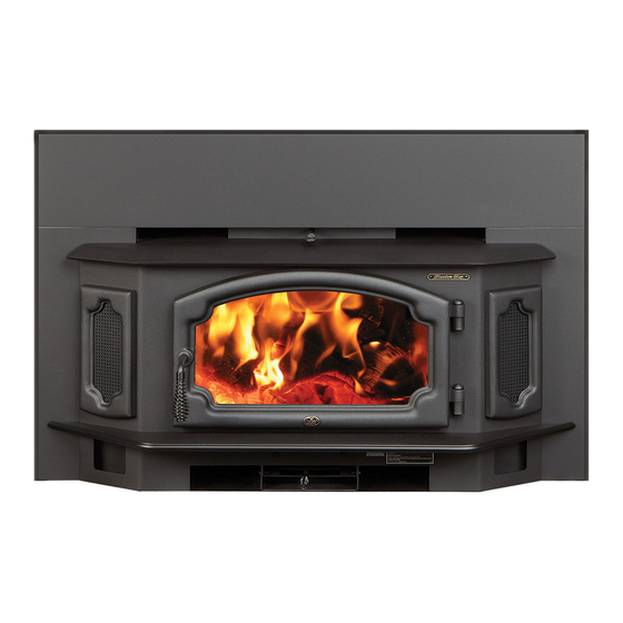
Lopi Freedom Bay ND Owner's Manual
Wood-burning masonry
fireplace insert
Hide thumbs
Also See for Lopi Freedom Bay ND:
- Owner's manual (33 pages) ,
- Owner's manual (34 pages) ,
- Owner's manual (32 pages)
Table of Contents
Advertisement
Quick Links
Freedom Bay Inbuilt
Owner's Manual
Wood-Burning Masonry
Fireplace Insert
Save these instructions for future
reference
SAFETY NOTICE:
If this appliance is not properly installed, a house fire may result.
For your safety, follow the installation directions. Contact local
building or fire officials about restrictions and installation
inspection requirements in your area.
Tested By:
Dragon Wholesaling Pty. Ltd.
Copyright 2015, Travis
AMDEL
Industries, Inc.
Unit 2, 16 Lexington Drive
8/26 Stirling St.
Thebarton, 5031, South Australia
Bella Vista NSW 2153
$10.00
100-01279
TESTED TO: AS/NZS 4013:1999
Australia
4141215
REPORT NUMBER: L4507/94
Advertisement
Table of Contents

Related Manuals for Lopi Lopi Freedom Bay ND


Summary of Contents for Lopi Lopi Freedom Bay ND
- Page 1 Freedom Bay Inbuilt Owner's Manual Wood-Burning Masonry Fireplace Insert Save these instructions for future reference SAFETY NOTICE: If this appliance is not properly installed, a house fire may result. For your safety, follow the installation directions. Contact local building or fire officials about restrictions and installation inspection requirements in your area.
-
Page 2: Introduction
Introduction Introduction We welcome you as a new owner of a Lopi Freedom Bay wood-burning fireplace insert. In purchasing a Lopi Freedom Bay you have joined the growing ranks of concerned individuals whose selection of an energy system reflects both a concern for the environment and aesthetics. The Lopi Freedom Bay is one of the finest appliances the world over. -
Page 3: Table Of Contents
Table of Contents Introduction ............2 Re-Loading the Stove ........17 Important Information ........2 Overnight Burn ..........17 Installation Options .......... 6 Normal Operating Sounds ......17 Features ............6 Hints for Burning ........... 18 ... - Page 4 Safety Precautions The viewing door must be Gasoline or other flammable closed and latched during liquids must never be used to operation. start the fire or "Freshen Up" the fire. Do not store or use gasoline or other flammable Never block free airflow through liquids in the vicinity of this the air vents on this appliance.
- Page 5 Safety Precautions Do not make any changes or modifications to an existing Do not place clothing or other masonry fireplace or chimney to flammable items on or near this install this appliance. appliance. Do not make any changes to the appliance to increase combustion air.
-
Page 6: Installation Options
Features & Specifications Installation Options Features Masonry Fireplace Insert EPA Phase II Approved WARNING: Do not install this fireplace insert into a 3.1 Cubic Feet (.087 m ) Firebox Volume factory-built metal (Z.C.) fireplace. Single Operating Control ... -
Page 7: Planning The Installation
Installation (for qualified installers only) SAFETY NOTICE: Please read this entire manual before you install and use your new room heater. Failure to follow instructions may result in property damage, bodily injury, or even death. Contact local building or fire officials about restrictions and installation inspection requirements in your area. -
Page 8: Fireplace Requirements
Installation (for qualified installers only) Fireplace Requirements Figure 2 shows the minimum size requirements for the type of fireplace used. Minimum Fireplace Size Masonry Fireplace Depth 15.75” 420mm Width (front) 29.25” 760mm Width (rear) 29.25” 760mm Height (front) 21.75" 570mm Figure 2 Fireplace Altered Tag Attach the "This fireplace has been altered..."... -
Page 9: Insert Placement Requirements
Installation (for qualified installers only) Insert Placement Requirements The insert must be placed so that no combustibles are within, or can swing within (e.g. drapes, doors), 36" (915mm) of the front of the insert Insert and hearth must be installed on a level, secure floor ... -
Page 10: Insert Rollers
Installation (for qualified installers only) Insert Rollers Two rollers are built into the back edge of the insert. This allows the insert to be rolled into position by lifting the front of the insert and pushing it into position (see Figure 4). Figure 4 Leveling Bolt Installation Two leveling bolts are pre-installed on the insert to... -
Page 11: Block-Off Plate Installation
Installation (for qualified installers only) Block-Off Plate Installation Whenever this appliance is installed with a direct connection a block-off plate, or other non-combustible seal-off device (e.g. damper adapter), will need to be installed. This device is used to seal the chimney, insuring no smoke enters the home and providing the chimney system with a seal to promote draft. -
Page 12: Insert With Positive Connection
Installation (for qualified installers only) Install a non-combustible Insert with Cap (prevents water cover plate to prevent water Positive from entering) from entering the chimney Connection NOTE: Flue Liner Most factory-built The liner must be chimney manufacturers stainless steel make stainless steel connector or flexible chimney liners, either vent. -
Page 13: Safety Notice
Operating Your Appliance Safety Notice: If this appliance is not properly installed, a house fire may result. For your safety, follow the installation directions. Contact local building or fire officials about restrictions and installation inspection requirements in your area. Read and follow all of the warnings on pages 4 and 5 of this manual. Before Your First Fire Verify the Installation Before starting the stove, verify that it is properly installed and all of the requirements in this manual have... -
Page 14: Bypass Operation
Operating Your Appliance Bypass Operation The bypass controls the flow of smoke inside the heater. When pulled out, smoke goes directly up the flue, creating more draft. When pushed in, the smoke goes around the baffle, utilizing the secondary combustion and making the heater more efficient. ... -
Page 15: Starting A Fire
Operating Your Appliance Starting a Fire Since the dawn of time man has debated the best way to start a fire. Some use the boy-scout "tee-pee", some prefer the "tic-tac-toe" stack. Either way, review the hints and warnings below to ensure proper fire starting. -
Page 16: Adjusting The Burn Rate
Operating Your Appliance Adjusting the Burn Rate Use the air control slider to control the burn rate of the stove. See the illustration below for details. Use the air control to change the burn rate. Low Burn High Burn (air control closed) (air control open) Approximate Air Control Settings: Overnight Burn... -
Page 17: Blower Operation
Operating Your Appliance Blower Operation The blower will turn HIGH on once the stove is Turn the dial all The high position Turn the dial up to temperature. the way counter- is all the way all the way This is typically 15 to clockwise until it counter-clockwise, clockwise. -
Page 18: Hints For Burning
Operating Your Appliance Hints for Burning Get the appliance hot before adjusting to low burn Use smaller pieces of wood during start-up and high burns to increase temperature Use larger pieces of wood for overnight or sustained burns ... -
Page 19: Troubleshooting
Operating Your Appliance Troubleshooting Problem Possible Cause Smoke Enters Room During Open the bypass (pg. 14). Start-Up Open the air control (pg. 16). Cold Air Blockage - burn a piece of newspaper to establish a draft. If the flame is not getting enough air, a small crack in the door is all that is needed. -
Page 20: Daily Maintenance (While Stove Is In Use)
Maintaining Your Appliance Failure to properly maintain and inspect your appliance may reduce the performance and life of the appliance, void your warranty, and create a fire hazard. Daily Maintenance (while stove is in use) Remove Ash (if necessary) Ash removal is not required once it builds up. -
Page 21: Monthly Maintenance (While Appliance Is In Use)
Maintaining Your Appliance Monthly Maintenance (while appliance is in use) Make sure the appliance has fully cooled prior to conducting service. Door and Glass Inspection The door must form an air-tight seal to the firebox for the stove to work correctly. Inspect the door gasket to make sure it forms an air-tight seal to the firebox. -
Page 22: Yearly Maintenance
Maintaining Your Appliance Yearly Maintenance Make sure the appliance has fully cooled prior to conducting service. Touch Up Paint Included with the owner's pack of this appliance is a can of Stove-Brite® paint. To touch up nicks or dulled paint, apply the paint while the appliance is cool. -
Page 23: Door Parts
Maintaining Your Appliance Door Parts 1/8” Hex Wrench # 20 Torx Driver NOTE: Place the glass gasket around the perimeter of the door retainer. 9/16" Wrench NOTE: Glue the door gasket to the door retainer. ID # Description Part # ID # Description Part #... -
Page 24: Firebox Parts
Maintaining Your Appliance Firebox Parts ID # Description Part # ID # Description Part # Air Tubes & Sleeve 98900210 Air Tube Roll Pins 98900357 NOTE: The Australian heater has only one air tube, at the rear of the firebox. Air Tube Retainer Sleeve 100-11001 Baffle Support, Front "Y"... -
Page 25: Baffle Removal & Replacement
Maintaining Your Appliance Baffle Removal & Replacement Lift up on the front portion of the front three firebricks. Lift the front baffle support “Y” and rotate it forward until it can be removed. Slide the center front firebrick forward and out the door opening. Then slide the side front firebricks towards the middle then out in the same manner. -
Page 26: Firebox Assembly
Limited 7 Year Warranty To register your 7 Year Warranty, complete the enclosed warranty card and mail it within ten (10) days of the Dragon Wholesaling Pty. Ltd., Unit 2, 16 Lexington Drive, Bella Vista appliance purchase date to:. NSW 2153, Australia . -
Page 27: If Warranty Service Is Needed
Notes CONDITIONS & EXCLUSIONS 1. This new appliance must be installed by a qualified installer. It must be installed, operated, and maintained at all times in accordance with the instructions in the Owner’s Manual. Any alteration, willful abuse, accident, neglect, or misuse of the product shall nullify this warranty. 2. -
Page 28: Listing Label
Listing Label Listing Label LOPI FREEDOM BAY INBUILT TESTED BY: AMDEL THEBARTON SOUTH AUSTRALIA 1999 APPLIANCE EMISSION FACTOR BURNING HARDWOOD = 2.5 g/Kg TESTED TO: AS/NZS 4013: 1999 REPORT NUMBER: L4507/94 Manufactured Exclusively for: DRAGON WHOLESALING PTY. LTD., INC. TRAVIS INDUSTRIES, INC. -
Page 29: Door Shell Installation
Optional Equipment Door Shell Installation 1. Remove the door retainer shipping latch following the directions below. Standard Screwdriver Rotate this shaft 1/4 turn clockwise until the door unlatches. Swing the door retianer open. Remove and discard the shipping latch and nut. Shipping Latch Door Retainer 9/16"... - Page 30 Optional Equipment 3. Attach the retainer to the shell following the directions below. Make sure the door retainer is centered on the door shell. You can gauge the alignment by looking at the gaps here. 1/8” Hex Wrench Once the door is aligned, tighten the two set screws on the bottom of the door shell to secure the door retainer.
-
Page 31: Surround Panels
Optional Equipment Surround Panels NOTE: Install the door shell (and side frames) prior to installing the surround panels. SURROUND PANEL SIZE HEIGHT WIDTH PART # 8" (203mm) 29-1/2" (750mm) 45-3/8" (1153mm) 99300293 10" (254mm) 31-1/2" (800mm) 49-3/8" (1254mm) 99300294 12" (305mm) 33-1/2"... - Page 32 Index Air Control (Burn Rate) .......... 16 Safety Label ............28 Air Tube Part Number ........... 24 Safety Precautions ..........4 Air Tube Removal & Replacement ......25 Smell ..............13 Ash Disposal ............20 Smoke Enters Room (Troubleshooting) ....19 Baffle Parts ............