Table of Contents
Advertisement
SERVICE MANUAL
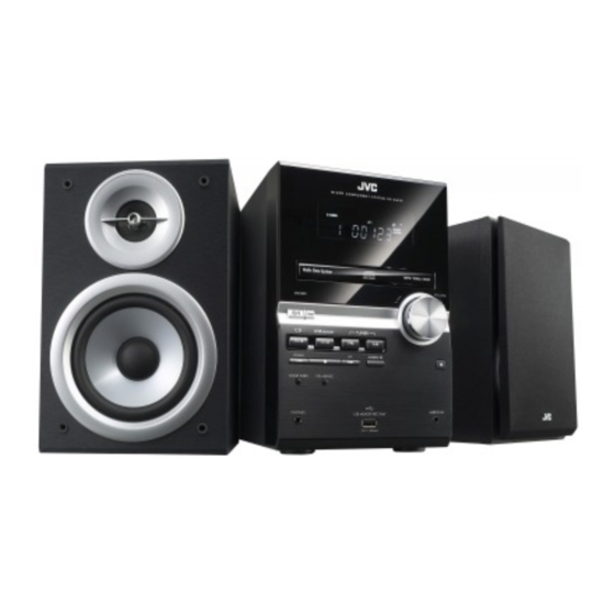
MICRO COMPONENT SYSTEM
8 S ERVICE MANUAL
2008
MB682<Rev.001>
UX-G950VB, UX-G950VE, UX-G950VEN,
UX-G950VEV, UX-G950VEE, UX-G650B,
UX-G650E, UX-G650EN, UX-G650EV
UX-G950V
SP-UXG950V
UX-G650
COPYRIGHT © 2008 Victor Company of Japan, Limited
Lead free solder used in the board (material : Sn-Ag-Cu, melting point : 219 Centigrade)
Lead free solder used in the board (material : Sn-Cu, melting point : 230 Centigrade)
1
Precaution. . . . . . . . . . . . . . . . . . . . . . . . . . . . . . . . . . . . . . . . . . . . . . . . . . . . . . . . . . . . . . . . . . . . . . . . . 1-4
2
Specific Service Instructions . . . . . . . . . . . . . . . . . . . . . . . . . . . . . . . . . . . . . . . . . . . . . . . . . . . . . . 1-7
3
Disassembly . . . . . . . . . . . . . . . . . . . . . . . . . . . . . . . . . . . . . . . . . . . . . . . . . . . . . . . . . . . . . . . . . . . . . . . 1-7
4
Adjustment . . . . . . . . . . . . . . . . . . . . . . . . . . . . . . . . . . . . . . . . . . . . . . . . . . . . . . . . . . . . . . . . . . . . . . . 1-18
5
Troubleshooting . . . . . . . . . . . . . . . . . . . . . . . . . . . . . . . . . . . . . . . . . . . . . . . . . . . . . . . . . . . . . . . . . 1-19
CA-UXG950V
SP-UXG950V
CA-UXG650
SP-UXG650
TABLE OF CONTENTS
COPYRIGHT © 2008 Victor Company of Japan, Limited
SUPER VIDEO
UX-G950VB / UX-G950VE
UX-G950VEE / UX-G950VEV
UX-G950VEE
SUPER VIDEO
SP-UXG650
No.MB682<Rev.001>
2008/8
Advertisement
Table of Contents

Related Manuals for JVC UX-G950VB


Summary of Contents for JVC UX-G950VB
- Page 1 SERVICE MANUAL MICRO COMPONENT SYSTEM MB682<Rev.001> 2008 8 S ERVICE MANUAL UX-G950VB, UX-G950VE, UX-G950VEN, UX-G950VEV, UX-G950VEE, UX-G650B, UX-G650E, UX-G650EN, UX-G650EV UX-G950V SUPER VIDEO UX-G950VB / UX-G950VE UX-G950VEE / UX-G950VEV UX-G950VEE SP-UXG950V CA-UXG950V SP-UXG950V UX-G650 SUPER VIDEO SP-UXG650 CA-UXG650 SP-UXG650 COPYRIGHT © 2008 Victor Company of Japan, Limited...
- Page 2 SPECIFICATION UX-G950V Amplifier section - CA-UXG950V 160 W (80 W + 80 W) at 6 Ω (10% THD) Output Power Audio Input AUDIO IN Stereo min. ( 3.5 mm) Ø 500 mV/47 kΩ (at “IN_LVL1”) 250 mV/47 kΩ (at “IN_LVL2”) 125 mV/47 kΩ...
- Page 3 Speakers - SP-UXG950V Speaker units Tweeter 4 cm cone x 1 Woofer 12 cm cone x 1 6 Ω Impedance 160 mm × 250 mm × 179 mm (W/H/D) Dimensions (approx.) Mass (approx.) 2.2 kg each Specifications and appearance are subject to change without prior notice. UX-G650 Amplifier section 120 W (60 W + 60 W) at 6 Ω...
-
Page 4: Precaution
SECTION 1 PRECAUTION Safety Precautions (1) This design of this product contains special hardware and voltmeter. many circuits and components specially for safety purpos- Move the resistor connection to each exposed metal es. For continued protection, no changes should be made part, particularly any exposed metal part having a return to the original design unless authorized in writing by the path to the chassis, and measure the AC voltage across... - Page 5 Preventing static electricity Electrostatic discharge (ESD), which occurs when static electricity stored in the body, fabric, etc. is discharged, can destroy the laser diode in the traverse unit (optical pickup). Take care to prevent this when performing repairs. 1.5.1 Grounding to prevent damage by static electricity Static electricity in the work area can destroy the optical pickup (laser diode) in devices such as laser products.
- Page 6 Important for laser products 1.CLASS 1 LASER PRODUCT 5.CAUTION : If safety switches malfunction, the laser is able to function. 2.CAUTION : (For U.S.A.) Visible and/or invisible class II laser radiation 6.CAUTION : Use of controls, adjustments or performance of when open.
-
Page 7: Specific Service Instructions
SECTION 2 SPECIFIC SERVICE INSTRUCTIONS This service manual does not describe SPECIFIC SERVICE INSTRUCTIONS. SECTION 3 DISASSEMBLY Main body (Used figure are UX-G950VE) 3.1.1 Removing the Metal cover (See Fig.1, 2) (1) Remove the two screws A attaching the Heat sink cover. (See Fig.1) (2) Remove the five screws B attaching the Metal cover. - Page 8 3.1.2 Removing the Front panel (see Fig.3 to 5) (1) Disconnect the card wire from Front panel connected to connector CN330 of the Micom board. (See fig.3) (2) Remove the two screws D attaching the both side of Front panel. (See Fig.4) (3) Disengage two hooks a engaged Front panel.
- Page 9 3.1.4 Removing the Amp board (See Fig.8 to 10) (1) Disconnect the Connector wire from Front jack board con- nected to connector CN201 of the Amp board. (See Fig.8) (2) Disconnect the card wire from Micom board connected to connector CN204 of the Amp board.
- Page 10 3.1.5 Removing the Rear panel (See Fig.11) (1) Remove the seven screws L attaching the Rear panel. Fig.11 3.1.6 Removing the DVD mechanism (See Fig.12, 13) (1) Disconnect the connector wire from Front jack board con- nected to connector CN811 of the Front end board.
- Page 11 3.1.7 Removing the Micom board (See Fig.14) (1) Remove the two screws M attaching the Micom board. Fig.14 3.1.8 Removing the Front jack board (See Fig.15) (1) Remove the three screws N attaching the Front jack board. Fig.15 3.1.9 Removing the Power board (See Fig.16) (1) Disconnect the connector wires from Power transformer CN805 CN804...
-
Page 12: See Fig.
3.1.11 Removing the Function board (See Fig.18) (1) Remove the Volume knob. (2) Remove the nine screws Q attaching the Function board. Fig.18 1-12 (No.MB682<Rev.001>) - Page 13 DVD mechanism 3.2.1 Removing the traverse mechanism (See Fig.1 to 6) (1) Remove the two screws A attaching the tramecha holder from top side of DVD mechanism assembly. (See Fig.1) Clamper base (2) Remove the two screws B attaching the DVD module board.
-
Page 14: No.mb682
DVD module board Solder short land section Fig.5 DVD module board CN101 CN201 Fig.3 DVD mechanism assembly Traverse mechanism assembly Fig.6 Fig.4 1-14 (No.MB682<Rev.001>))1 - Page 15 3.2.2 Removing the pickup assembly (See Fig.7 to 11) (1) Remove the two rod springs pressing the guide shaft. (See Fig.7) (SHAFT) (2) Remove the screw E and F attaching the spring holder. (See Fig.8) (3) Remove the read screw from traverse mechanism assem- (T.TABLE) bly.
- Page 16 3.2.3 Removing the feed motor assembly (See Fig.12) (1) Remove the one screw G attaching the feed motor assem- bly. Solder part (2) Remove the feed motor wires from solder part of spindle motor board. Middle gear Lead screw Fig.12 3.2.4 Removing the spindle motor assembly (See Fig.13) (1) Remove the three screws H attaching the spindle motor...
-
Page 17: No.mb682
3.2.5 Removing the tray assembly (See Fig.14 & 15) (1) Remove the two screws J attaching the clamper base. (See Fig.14) (2) Remove the one screw K attaching the shaft guide from bottom side. (See Fig.14) (3) Remove the two screws L attaching the shaft guide from top side. -
Page 18: Adjustment
SECTION 4 ADJUSTMENT ATTENTION IN SERVICE OF DVD SECTION (1) When pickup, Flash ROM ,DVD module board were changed, initialize EEPROM by all means. (2) When full initialization was excuted, excute learning with a DVD test disc by all means. Test disc : VT-501, VT-502 Learning method : It is adjusted automatically by normal playback of a DVD disc. -
Page 19: Troubleshooting
SYSTEM MICOM TEST MODE CAUTION: The operation please use the button of the remote controller. (1) In DVD/CD mode, press "SET" key + "9" key + "POWER" key repeatedly. System Micom version G650 : "51353 00" (1st issued) G950V : "50852 01" (1st issued + ROM Corr) DVD/CD Micom version "DVD 0268"... - Page 20 Victor Company of Japan, Limited Audio/Video Systems Division 10-1,1chome,Ohwatari-machi,Maebashi-city,371-8543,Japan (No.MB682<Rev.001>) Printed in Japan...
-
Page 21: Parts List
PARTS LIST UX-G950VB,UX-G950VE,UX-G950VEN UX-G950VEV,UX-G950VEE,UX-G650B UX-G650E,UX-G650EN,UX-G650EV * All printed circuit boards and its assemblies are not available as service parts. - Contents - 3- 2 Exploded view of general assembly and parts list (Block No.M1) 3- 6 DVD mechanism assembly and parts list (Block No.MJ) 3- 8 DVD loading base assembly and parts list (Block No.MN) -
Page 22: Exploded View Of General Assembly And Parts List
Exploded view of general assembly and parts list Block No. Only UX-G650 series FL board Power amplifier board Mic & Switch board Primary board Only UX-G950V series Only Jack board UX-G950V series Only UX-G950VB E,EN,EV Jack board... - Page 23 Only UX-G950V series Only UX-G650 series fier Primary board Except UX-G950VEE Jack board Micom board The parts without symbol number are not service.
- Page 24 General Assembly Block No. [M][1][M][M] Symbol No. Part No. Part Name Description Local GV10423-002A FRONT PANEL 950VB,950VE,950VEN,950VEV,950VEE GV10423-001A FRONT PANEL 650B,650E,650EN,650EV GV40313-002A FELT SPACER (x2) GV20511-002A FRONT LENS 950VB,950VE,950VEN,950VEV,950VEE GV20511-001A FRONT LENS 650B,650E,650EN,650EV GV20518-001A VOL.ORNAMENT B 950VB,950VE,950VEN,950VEV,950VEE GV20515-001A VOL.ORNAMENT A 650B,650E,650EN,650EV GV20512-002A FRONT COVER A...
- Page 25 Symbol No. Part No. Part Name Description Local QMPN150-200-JC POWER CORD(EK) 2m BLACK 950VB,650B QMPK200-200-JD POWER CORD 2m BLACK 950VE,950VEN,950VEV,950VEE,650E,650EN,650EV QMF51W2-2R0-J8 FUSE 2A AC250V 950VB,950VE,950VEN,950VEV,950VEE QMF51W2-1R6-J8 FUSE 1.6A AC250V 650B,650E,650EN,650EV QMF51W2-2R0-J8 FUSE 2A AC250V QYSDSG3008ZA TAP SCREW M3 x 8mm QYSDSG3008ZA TAP SCREW M3 x 8mm...
- Page 26 DVD mechanism assembly and parts list Block No. FXL-D10-1M Grease =JVG-31N =JVS-1003 =1401C < Back side > 7.0mm 0.2mm The parts without symbol number are not service.
- Page 27 DVD mechanism Block No. [M][J][M][M] Symbol No. Part No. Part Name Description Local LV22234-003A T.M.CHASSIS LV22235-002A SPINDLE BASE QYSDST2005ZA TAP SCREW M2 x 5mm(x2) LV36555-001A G.S.HOLDER QYSDST2005ZA TAP SCREW M2 x 5mm LV44041-002A GUIDE SHAFT LV44479-001A BAR SPRING LV22236-001A FEED HOLDER QAR0165-001 FEED MOTOR 5.0V DC...
- Page 28 DVD loading base assembly and parts list Block No. FMU-MB6-71M Grease JVS-1003 CFD-4007ZY2 < Back side > 7.75mm 0.10mm Back side DVD module board DVD loading switch board The parts without symbol number are not service.
- Page 29 DVD loading base assembly Block No. [M][N][M][M] Symbol No. Part No. Part Name Description Local LV11065-014A LOADER SUB ASSY E407140-001SS C.D ROLLER E407149-001SS RUBBER TUBE LV10979-003A TRAY LV35499-003A SHAFT GUIDE LV44022-001A SHAFT QYSSSF2008ZA TAP SCREW M2 x 8mm QYSDSF2008ZA TAP SCREW M2 x 8mm(x2) QAR0197-001 MOTOR...
-
Page 30: Electrical Parts List
Electrical parts list Main board Symbol No. Part No. Part Name Description Local Block No. [0][1] D2101 MA111-X SI DIODE Symbol No. Part No. Part Name Description Local D2201 MA111-X SI DIODE D2501 MC2838-X DIODE D2502 MA111-X SI DIODE IC100 PT6315 D2751 MA8120/M/-X... - Page 31 Symbol No. Part No. Part Name Description Local Symbol No. Part No. Part Name Description Local C2032 QETN2AM-476Z E CAPACITOR 47uF 100V M C2771 QETN1HM-105Z E CAPACITOR 1uF 50V M C2041 QETN1CM-107Z E CAPACITOR 100uF 16V M C2801 QEKC1HM-106Z E CAPACITOR 10uF 50V M C2101 NDC31HJ-101X...
- Page 32 Symbol No. Part No. Part Name Description Local Symbol No. Part No. Part Name Description Local C4402 NCB31CK-104X C CAPACITOR 0.1uF 16V K 950VB,950V R2105 QRJ143J-561X UNF C RESISTOR 560Ω 1/4W J 950VB,950V E,950VEN,9 E,950VEN,9 50VEV,950V 50VEV,950V C4403 NCB31CK-105X C CAPACITOR 1uF 16V K 950VB,950V R2105...
- Page 33 Symbol No. Part No. Part Name Description Local Symbol No. Part No. Part Name Description Local R2502 NRSA63J-362X MG RESISTOR 3.6kΩ 1/16W J R3075 NRSA63J-103X MG RESISTOR 10kΩ 1/16W J 950VB,950V E,950VEN,9 R2503 NRSA63J-124X MG RESISTOR 120kΩ 1/16W J 50VEV,950V R2504 NRSA63J-513X MG RESISTOR...
- Page 34 Symbol No. Part No. Part Name Description Local Symbol No. Part No. Part Name Description Local R3713 NRSA63J-753X MG RESISTOR 75kΩ 1/16W J R4504 NRSA63J-201X MG RESISTOR 200Ω 1/16W J 950VB,950V E,950VEN,9 R3714 NRSA63J-104X MG RESISTOR 100kΩ 1/16W J 50VEV,950V R3720 QRK126J-470X UNF C RESISTOR...
-
Page 35: Switch Board
Symbol No. Part No. Part Name Description Local Symbol No. Part No. Part Name Description Local K1002 NQR0627-002X FERRITE 1.5K/ R6601 NRSA63J-202X MG RESISTOR 2kΩ 1/16W J 100MHz200mA0 R6602 NRSA63J-302X MG RESISTOR 3kΩ 1/16W J R6603 NRSA63J-512X MG RESISTOR 5.1kΩ 1/16W J K3301 QQR0621-001Z FERRITE BEADS... - Page 36 Symbol No. Part No. Part Name Description Local Symbol No. Part No. Part Name Description Local IC505 or K4S641632H-UC75 C340 NCB30JK-105X C CAPACITOR 1uF 6.3V K IC509 SG32M90TFICB29A IC(PROGRAMED) C341 NCB30JK-105X C CAPACITOR 1uF 6.3V K IC510 S-24CS16A0I-G-X C345 NCB31CK-104X C CAPACITOR 0.1uF 16V K IC701...
- Page 37 Symbol No. Part No. Part Name Description Local Symbol No. Part No. Part Name Description Local R214 NRSA63J-103X MG RESISTOR 10kΩ 1/16W J CN201 QGF1016F8-08W CONNECTOR FFC/FPC (1-8) R219 NRSA63J-183X MG RESISTOR 18kΩ 1/16W J CN701 QGF1016F8-25W CONNECTOR FFC/FPC (1-25) R220 NRSA63J-243X MG RESISTOR...
-
Page 38: Packing Materials And Accessories Parts List
Packing materials and accessories parts list Block No. No additional / supplemental order of WARRANTY CARDs are available. Only 950VE,EN,EV,EE Only 650E,EV Only 650EN A1,A7 A1,A2,A3 A1,A2,A3 A8,A9 A4,A5,A7 A4,A7,A8 A8,A9 Only 950VEE Only 950VB,650B A1,A6 A7,A8 3-18... - Page 39 Packing and Accessories Block No. [M][3][M][M] Symbol No. Part No. Part Name Description Local GVT0254-001A INST BOOK 950VB GVT0254-002A INST BOOK GER FRE ITA DUT 950VE GVT0254-003A INST BOOK SPA DAN FIN SWE POR 950VEN GVT0254-004A INST BOOK HUN CZE POL 950VEV GVT0254-005A INST BOOK...
-
Page 40: Micro Component System
SCHEMATIC DIAGRAMS MICRO COMPONENT SYSTEM UX-G950VB, UX-G950VE, UX-G950VEN, UX-G950VEV, UX-G950VEE, UX-G650B, UX-G650E, UX-G650EN, UX-G650EV DVD-ROM No.SML2008Q2 UX-G950V SUPER VIDEO UX-G950VB / UX-G950VE UX-G950VEE / UX-G950VEV UX-G950VEE SP-UXG950V CA-UXG950V SP-UXG950V UX-G650 SUPER VIDEO SP-UXG650 CA-UXG650 SP-UXG650 Lead free solder used in the board (material : Sn-Ag-Cu, melting point : 219 Centigrade) - Page 41 In regard with component parts appearing on the silk-screen printed side (parts side) of the PWB diagrams, the parts that are printed over with black such as the resistor ( ), diode ( ) and ICP ( ) or identified by the " " mark nearby are critical for safety.
-
Page 42: Block Diagram
Block diagram Front panel section System control section TU_CE, TU_CK, S2TDT, T2SDT TUAMSW, RDSCLK, RDSDATA FL & Remocon REMOCON IC101 REMOCON FLDATA TUNER FLLATCH X3001 REMOCON PACK TUL/R FLCLK 8MHz STBLED G1 to 11 DI100 JOG+/- P1 to 16 FLDATA KEY1 to 3 FLLATCH FL DISPLAY... - Page 43 Standard schematic diagrams Primary section GVA10164-A1 WR801 QUM155-14DGZ4-E 3.3V POUTRLY 3.3V 3.3V 8.2V 8.2V CN804 QGA3901C1-05 F8001 T2AL/250V WR802 8.2V QUM154-14DGZ4-E 8.2V 44.2V 44.2V S1CT QUM153-14DGZ4-E WR803 IC800 -44.1V KBJ4J -44.1V C8100 0.1/100 C8102 C8101 CN805 QGA7901C1-03 RY800 0.8V 0.2V FOR UX-G980 (US/UN/UG) ONLY (220V &...
- Page 44 Micom section UX-G650 ALL NI OPTICAL OUT IC330 GP1FAV30TK0F WR390 QUB220-20DMHP-E WR320 WR321 CN330 CN301 TU_CE QUM155-12DGZ4-E GVA10165-A1(1/2) QUM154-12DGZ4-E TU-CE QGF1208C1-17 QGF1208C1-19 C3350 T2SDT 0.1/16 3.3V TU-DI TU_CK 3.3V TU-CK S2TDT 3.8V TU-DO C3381 AGND TU-L R3380 TU9V R3381 TU-R UX-G650 ALL NI S.W.OUT DGND...
- Page 45 Video section GVA10165-A1(2/2) FOR G650 ALL NI J4001 VIDEO DRIVER QNN0779-001 R4001 R4500 IC401 R4002 MM1623XF-X R4501 B4000 5.3V 5.3V C4402 C4401 R4003 L4003 0.1/16 R4502 QUY158-050Y 2.5V C4403 S-DCOUT C IN 1/16 R4503 2.5V B4009 VMUTE MUTE1 C OUT 1.6V C4404 R4504...
- Page 46 Amp section WR801&WR802&WR803 OF GVA10164-A1 WR203&WR204 OF GVA10165-A1 QAR0392-002 CN210 CN211 CN212 QGD2504C1-05Z QGD2504C1-03Z FROM TRANSFORMER QGD2504C1-04Z CN209 QGA3901C1-02 CN208 CN207 QGD2504C1-05Z QGD2504C1-04Z GVA10165-A2 -23.7V IC202 -23.7V KBJ4J IC201 W201 VOLTAGE DOUBLE W202 D2033 16.4V KTA1504/YG/-X C2024 C2031 B2808 1N4003S-T5 TO FAN 8.2V 0.1/100...
- Page 47 LCD & Jack section GVA10164-A4 B5000 WR500 QUM154-22DGZ4-E HPSW L5000 C5004 C5002 JACK K5000 0.01/50 GVA10165-A3 AGND B5001 C5001 C5003 0.01/50 L5001 C1001 B5002 C1000 J5000 QNS0188-001 44 43 42 41 40 39 38 37 36 35 34 33 32 31 30 29 28 27 26 25 24 23 22 21 20 19 18 17 16 15 14 13 12 11 10 DI100 L5101 J5100...
- Page 48 Mic & Key switch section *** ALL NI CN602 WR602 QGF1208F1-11 QGA2501C1-05 W681 K6004 K6800 QQR0621-001Z B6004 R6114 QUY150-050Y 1.5K C6117 C6009 2.2/50 100/16 W682 R6015 B6801 K6801 R6011 JOG+ C6008 0.22/50 K6802 3.9V JOG- C6105 Q6101 KRC102S-X B6802 R6105 10/25 C6800 D6800...
- Page 49 Front end 1 section K354 48MHz NQR0022-002X C370 D1.2V REG. C328 0.01 DVDPWR 3.9V Cont D1.2V 1.2V P3.3V C302 47/4 IC302 MM1701CH-X CN301 for ICE D301 DGND CPURST RESET EEPROM R306 1k SCLK C564 DGND R307 1k SDATA DGND 54 53 52 51 50 49 48 47 46 45 44 43 42 41 40 39 38 37 36 35 34 33 32 31 30 29 28 27 26 25 24 23 22 21 20 19 18 17 16 15 14 13 12 11 10 9 UCLK R353 (UCLK)
- Page 50 Front end 2 section SDRAM FLASH ROM IC505 IC509 SG32A90TFIR3 K4S641632K-UC75 EXADT15 0.4V 0.5V EXADR16 C560 3.3V EXADT14 0.7V 3.3V 2.8V 2.7V MDQ15 MDQ0 */BYTE DQ15 EXADT13 0.5V C551 3.3V VDDQ VSSQ EXADT12 0.7V 0.8V EXDT15 2.8V 2.7V MDQ14 MDQ1 DQ14 EXADT11 0.7V...
- Page 51 Front end 3 section Loader section LOADING MOTOR QAR0197-001 QSW1074-001 DGND OPENDET P3.3V CLOSEDET QGF1016F3-05 LVA10530-01A DGND R859 R860 5V REG Q801 KRA104S-X IC801 MM1565AF-X RT1P441C-X R891 Vout CN801 QGF1016F8-05W 3.3V IC891 Cont Q802 C819 CN811 QGA2001F6-05X R819 R811 1/2W K811 R812 K812...
-
Page 52: Printed Circuit Boards
Printed circuit boards Primary board Lead free solder used in the board (material : Sn-Ag-Cu, melting point : 219 Centigrade) Lead free solder used in the board (material : Sn-Cu, melting point : 230 Centigrade) (Primary board) (Jack board) J5100 D5300 D5200 D5400... - Page 53 Micom board Amp board Lead free solder used in the board (material : Sn-Ag-Cu, melting point : 219 Centigrade) Lead free solder used in the board (material : Sn-Ag-Cu, melting point : 219 Centigrade) Lead free solder used in the board (material : Sn-Cu, melting point : 230 Centigrade) Lead free solder used in the board (material : Sn-Cu, melting point : 230 Centigrade) R3200 C3206...
- Page 54 Front end board Lead free solder used in the board (material : Sn-Ag-Cu, melting point : 219 Centigrade) Lead free solder used in the board (material : Sn-Cu, melting point : 230 Centigrade) forward side R104 LVB10824-002A R103 Q101 R129 R107 R109 R291...
- Page 55 Victor Company of Japan, Limited Audio/Video Systems Category 10-1,1chome,Ohwatari-machi,Maebashi-city,371-8543,Japan Printed in Japan (No.MB682SCH<Rev.001>)