Table of Contents
Advertisement
Quick Links
SERVICE MANUAL
MICRO COMPONENT SYSTEM
6
2005
MB408
UX-GD6S,UX-GD6M
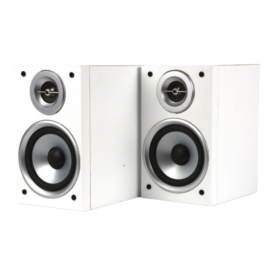
SP-UXGD6S
SUPER VIDEO
Area suffix
A ------------------------ Australia
US ------------------------ Singapore
UT ---------------------------- Taiwan
UW ----------- Brazil,Mexico,Peru
UX -------------------- Saudi Arabia
UG --- Turkey,South Africa,Egypt
UN ----------------------------- Asean
Lead free solder used in the board (material : Sn-Ag-Cu, melting point : 219 Centigrade)
1
PRECAUTION. . . . . . . . . . . . . . . . . . . . . . . . . . . . . . . . . . . . . . . . . . . . . . . . . . . . . . . . . . . . . . . . . . . . . . . . . 1-3
2
SPECIFIC SERVICE INSTRUCTIONS . . . . . . . . . . . . . . . . . . . . . . . . . . . . . . . . . . . . . . . . . . . . . . . . . . . . . . 1-6
3
DISASSEMBLY . . . . . . . . . . . . . . . . . . . . . . . . . . . . . . . . . . . . . . . . . . . . . . . . . . . . . . . . . . . . . . . . . . . . . . . 1-7
4
ADJUSTMENT . . . . . . . . . . . . . . . . . . . . . . . . . . . . . . . . . . . . . . . . . . . . . . . . . . . . . . . . . . . . . . . . . . . . . . . 1-31
5
TROUBLESHOOTING . . . . . . . . . . . . . . . . . . . . . . . . . . . . . . . . . . . . . . . . . . . . . . . . . . . . . . . . . . . . . . . . . 1-35
CA-UXGD6S
SP-UXGD6S
UX-GD6S
TABLE OF CONTENTS
COPYRIGHT © 2005 Victor Company of Japan, Limited
SP-UXGD6M
CA-UXGD6M
UX-GD6M
Area suffix
UB ---------------------- Hong Kong
UF ------------------------------ China
UP ----------------------------- Korea
UT ---------------------------- Taiwan
UG --- Turkey,South Africa,Egypt
SP-UXGD6M
No.MB408
2005/6
Advertisement
Table of Contents

Related Manuals for JVC UX-GD6M


Summary of Contents for JVC UX-GD6M
-
Page 1: Table Of Contents
SERVICE MANUAL MICRO COMPONENT SYSTEM MB408 2005 UX-GD6S,UX-GD6M SP-UXGD6S CA-UXGD6S SP-UXGD6S SP-UXGD6M CA-UXGD6M SP-UXGD6M SUPER VIDEO UX-GD6S UX-GD6M Area suffix Area suffix A ------------------------ Australia UB ---------------------- Hong Kong US ------------------------ Singapore UF ------------------------------ China UT ---------------------------- Taiwan UP ----------------------------- Korea... - Page 2 SPECIFICATION CA-UXGD6S (for UX-GD6S)/CA-UXGD6M (for UX-GD6M) 100 W (50 W + 50 W) at 6 Ω (10% THD) Amplifier section Output Power Audio Input AUX 400 mV/50 kΩ (at "AUX LVL1") 200 mV/50 kΩ (at "AUX LVL2") Digital output DVD OPTICAL DIGITAL OUT: -21 dBm to -15 dBm (660 nm ±30 nm)
-
Page 3: Precaution
SECTION 1 PRECAUTION Safety Precautions (1) This design of this product contains special hardware and voltmeter. many circuits and components specially for safety purpos- Move the resistor connection to each exposed metal es. For continued protection, no changes should be made part, particularly any exposed metal part having a return to the original design unless authorized in writing by the path to the chassis, and measure the AC voltage across... - Page 4 Preventing static electricity Electrostatic discharge (ESD), which occurs when static electricity stored in the body, fabric, etc. is discharged, can destroy the laser diode in the traverse unit (optical pickup). Take care to prevent this when performing repairs. 1.5.1 Grounding to prevent damage by static electricity Static electricity in the work area can destroy the optical pickup (laser diode) in devices such as laser products.
-
Page 5: Important For Laser Products
Important for laser products 5.CAUTION : If safety switches malfunction, the laser is able 1.CLASS 1 LASER PRODUCT to function. 2.DANGER : Invisible laser radiation when open and inter 6.CAUTION : Use of controls, adjustments or performance of lock failed or defeated. Avoid direct exposure to beam. procedures other than those specified here in may result in 3.CAUTION : There are no serviceable parts inside the hazardous radiation exposure. -
Page 6: Specific Service Instructions
SECTION 2 SPECIFIC SERVICE INSTRUCTIONS This service manual does not describe SPECIFIC SERVICE INSTRUCTIONS. 1-6 (No.MB408) -
Page 7: Disassembly
SECTION 3 DISASSEMBLY Main body section 3.1.1 Removing the metal cover (See Figs.1 to 3) (1) From the back side of the main body, remove the six screws A attaching the metal cover. (See Fig.1.) (2) From the both sides of the main body, remove the two screws B attaching the metal cover. -
Page 8: No.mb408)1
3.1.2 Removing the front panel assembly (See Figs.4 to 6) • Remove the metal cover. (1) From the bottom side of the main body, remove the two screws C attaching the front panel assembly. (See Fig.4.) (2) From the right side of the main body, push the slide cam and pull the tray assembly out of the main body in the di- rection of the arrow 1. - Page 9 3.1.3 Removing the rear cover (See Fig.7) • Remove the metal cover. (1) From the back side of the main body, remove the screw D attaching the rear cover. Rear cover (2) Release the joint sections c and remove the rear cover. Fig.7 (No.MB408)1-9...
- Page 10 3.1.4 Removing the cassette chassis assembly (See Figs.8 to 10) • Remove the metal cover and rear cover. (1) Remove the two screws E attaching the cassette chassis assembly. (See Fig.8.) (2) From the both sides of the main body, release the joints d and lift the cassette chassis assembly in the direction of the arrow.
- Page 11 3.1.5 Removing the tuner (See Figs.11 and 12) • Remove the metal cover, rear cover and cassette chassis as- sembly. Tuner (1) From the back side of the main body, remove the two screws F attaching the tuner to the rear panel. (See Fig.11.) (2) Disconnect the card wire from the connector on the...
- Page 12 3.1.6 Removing the rear panel (See Fig.13) • Remove the metal cover and rear cover. (1) Remove the fifteen screws G attaching the rear panel. Rear panel (2) Remove the two screws H attaching the rear panel. [Only for US version] (3) Release the joint sections e and remove the rear panel.
- Page 13 3.1.8 Removing the AC board (See Fig.15) • Remove the metal cover, rear cover and cassette chassis as- sembly. (1) From the back side of the main body, remove the two AC board CN904 screws J. (2) From the left side of the main body, remove the screw K and screw M attaching the AC board.
- Page 14 3.1.9 Removing the micom board (See Figs.16 and 17) • Remove the metal cover, front panel assembly, rear cover and cassette chassis assembly. Micom board (1) From the back side of the main body, remove the two screws N attaching the micom board to the rear panel. (See Fig.16.) (2) From the right side of the main body, remove the screw P attaching the micom board.
- Page 15 3.1.10 Removing the speaker board (See Fig.18) • Remove the metal cover, rear cover and rear panel. (1) From the right side of the main body, disconnect the con- Speaker board nector CN310 on the speaker board toward this side. CN310 (2) Remove the speaker board from the joint section h in the direction of the arrow.
- Page 16 3.1.12 Removing the heat sink (See Fig.20) • Remove the metal cover, front panel assembly, rear cover, cassette chassis assembly, tuner, rear panel, video board, AC Support board 2 board, micom board, speaker board and amplifier board. (1) From the forward side of the amplifier board, remove the Heat sink IC bracket four screws R.
- Page 17 3.1.14 Removing the power transformer (See Fig.22) • Remove the metal cover, front panel assembly, rear cover, cassette chassis assembly, tuner, rear panel, video board, AC Shield case board, micom board, speaker board and amplifier board. (1) Remove the wire holder fixing the wire. Reference: When connecting the wires, fix it with the wire holder as before.
- Page 18 3.1.16 Removing the AUX board and headphone board (See Fig.24) • Remove the metal cover, front panel assembly, rear cover, cassette chassis assembly, tuner, rear panel, video board, AC AUX board Headphone board board, micom board, speaker board and amplifier board. (1) Remove the screw V attaching the AUX board on the bot- tom chassis.
- Page 19 3.1.19 Removing the front panel board (See Figs.26 and 27) • Remove the metal cover and front panel assembly. (1) From the front side of the front panel assembly, pull out the Front panel assembly volume knob in the direction of the arrow. (See Fig.26.) (2) From the inside of the front panel assembly, remove the nine screws Z and screw Z' attaching the front panel board.
- Page 20 DVD mechanism section • Remove the DVD mechanism assembly from the main body. (See "Removing the DVD mechanism assembly".) 3.2.1 Removing the traverse mechanism assembly (See Fig.1) From the bottom side of the DVD mechanism assembly, remove the four screws A attaching the traverse mechanism assembly DVD mechanism assembly and take out the traverse mechanism assembly with the DVD Traverse mechanism assembly...
- Page 21 3.2.2 Removing the DVD module board (See Figs.2 and 3) • Remove the traverse mechanism assembly. (1) From the side of the traverse mechanism assembly, solder DVD pickup the short land sections a on the DVD pickup. (See Fig.2.) (2) From the bottom side of the traverse mechanism assem- bly, release the lock of the connector CN101 on the DVD...
-
Page 22: See Figs.2,4 To
3.2.3 Removing the DVD pickup (See Figs.2,4 to 6) • Remove the traverse mechanism assembly. (1) From the side of the traverse mechanism assembly, solder Traverse mechanism assembly the short land sections a on the DVD pickup. (See Fig.2.) (2) Release the lock of the connector on the DVD pickup in the Rod spring Guide shaft direction of the arrow and disconnect the card wire. - Page 23 3.2.4 Attaching the DVD pickup (See Figs.2,4 to 7) • See "3.2.3 Removing the DVD pickup". (1) Attach the guide shaft, rack arm and rack arm spring to the Screw shaft gear DVD pickup. (See Fig.6.) (2) Align the DVD pickup to the section h of the traverse mech- anism assembly first, and set the both ends of the guide shaft of the DVD pickup in the sections f and g of the traverse mechanism assembly.
-
Page 24: Reference
3.2.5 Removing the feed motor (See Figs.4,8 and 9) • Remove the traverse mechanism assembly. (1) From the top side of the traverse mechanism assembly, re- move the screw C and remove the feed bracket from the sections d. (See Fig.4.) (2) Release the claw e of the thrust spring in the direction of the arrow and remove the thrust spring. -
Page 25: See Fig.
3.2.7 Removing the DVD loading switch board (See Fig.10.) (1) From the bottom side of the DVD mechanism assembly, re- move the wires from the soldered sections n on the DVD DVD loading switch board loading switch board. (2) Remove the screw G attaching the DVD loading switch Tray assembly board. -
Page 26: No.mb408)1
DVD mechanism assembly Tray assembly Fig.13 Motor pulley Belt DVD mechanism assembly Fig.14 1-26 (No.MB408) - Page 27 Cassette mechanism assembly 3.3.1 Removing the Play/Record & Clear head Cassette mechanism assembly Fly wheelR (See Fig.1~3) (1) While moving the trigger arm on the right side of the head mount in the direction of the arrow, turn the flywheel R counterclockwise until the head mount comes ahead and clicks.
- Page 28 3.3.2 Removing the head amplifier & mechanism control board (See Fig.4) (1) Turn over the cassette mechanism assembly and remove Main motor assembly the three screws A attaching the head amplifier & mecha- nism control board. Capstan belt (2) Disconnect the flexible wire from connector CN31 on the head amplifier &...
- Page 29 3.3.4 Removing the flywheel (See Fig.8, 9) • Prior to performing the following procedure, remove the head amplifier & mechanism control board and the main motor as- sembly. (1) From the front side of the cassette mechanism, remove the slit washers attaching the capstan shaft L and R. Pull out the flywheels backward.
- Page 30 3.3.6 Reattaching the Play/ Record & Clear head (See Fig.11~13) (1) Reattaching the head mount assembly. a) Change front of the direction cover of the head mount assembly to the left (Turn the head forward). b) Fit the bosses O', P', Q', U' and V' on the head mount assembly to the holes P and V, the slots O, U and Q of the mechanism sub assembly (See Fig.11 to 13).
-
Page 31: Adjustment
SECTION 4 ADJUSTMENT Service mode 4.1.1 Confirming contents (1) Tuner AM switch to 9kHz-step (2) Tuner AM switch to 10kHz-step (3) Cold start (4) Tray lock (5) DVD test mode (6) DVD initialize 4.1.2 Confirming methods 1. Tuner AM switch to 9kHz-step 3. - Page 32 5. DVD test mode 6. DVD initialize In to the DVD test mode. DVD module initialized. Test mode contents is refer to module specification. LCD segment is light on at initialize command. DVD test mode is canceled by POWER OFF and except source DVD.
- Page 33 4. DVD check mode DVD test mode Press the [MENU] key on the remote controller . FL indication " CHECK " START PLAYBACK Press the [1] key on FL indication the remote controller . " PLAYBACK " (After 2 seconds) Perform SEARCH TNO+1 Press the [2] key on FL indication...
- Page 34 (After 2 seconds) Perform monitor output. Press the [0] key on FL indication FL indication the remote controller . "MONITOR" "xxxxyyyy" Initialize EEPROM (MECHA) Press the [+10] key on FL indication the remote controller . "INIT" Start PLAYING and obtain LASER CURRENT and JITTER value.
-
Page 35: Troubleshooting
SECTION 5 TROUBLESHOOTING This service manual does not describe TROUBLESHOOTING. (No.MB408)1-35... - Page 36 Victor Company of Japan, Limited AV & MULTIMEDIA COMPANY AUDIO/VIDEO SYSTEMS CATEGORY 10-1,1chome,Ohwatari-machi,Maebashi-city,371-8543,Japan (No.MB408) Printed in Japan...
- Page 37 SCHEMATIC DIAGRAMS MICRO COMPONENT SYSTEM UX-GD6S,UX-GD6M CD-ROM No.SML200506 UX-GD6S Area suffix A ------------------------ Australia US ------------------------ Singapore UT ---------------------------- Taiwan UW ----------- Brazil,Mexico,Peru UX -------------------- Saudi Arabia UG --- Turkey,South Africa,Egypt UN ----------------------------- Asean (SP-UXGD6S) (CA-UXGD6S) (SP-UXGD6S) UX-GD6M Area suffix...
- Page 38 In regard with component parts appearing on the silk-screen printed side (parts side) of the PWB diagrams, the parts that are printed over with black such as the resistor ( ), diode ( ) and ICP ( ) or identified by the " " mark nearby are critical for safety.
-
Page 39: Block Diagram
Block diagram DVD tray loading DVD module section Amplifier section switch section LOADING A, B, C, D, E1+F1,E2+F2,E3+F3,E4+F4 S2UDT,U2SDT,UCLK,SCS,UCS OPEN MOTOR RF+,RF-,PD(CD),PD(DVD) CPURST,TX,DAC1OUT,DAC2OUT IC302 CLOSE DVD pickup DAC3OUT,DAC4OUT,DAC5OUT LOADING LPCO1 mechanism OPENDET CPURST LPCO2 DRIVER EXDT0 to 15,EXADT0 to 15 IC302 DVDPWR CLOSEDET... - Page 40 Standard schematic diagrams Transformer and rectifiers section C9007 C9003 C9007 C9003 D9007 D9003 F9003 D9003 F9003 D9007 1N5402M-20 1N5402M-20 QMF51W2-5R0-J8 1N5402M-20 1N5402M-20 QMF51W2-5R0-J8 D9008 D9004 D9008 D9004 1N5402M-20 1N5402M-20 1N5402M-20 1N5402M-20 C9008 C9004 C9004 F9002 C9008 F9002 QMF51W2-5R0-J8 QMF51W2-5R0-J8 F9004 F9004 QMF51W2-2R0-J8 F9005...
- Page 41 QQR0621-001Z 1N4003S-T5 1N4003S-T5 B3061 K3007 D3403 J3800 1N4003S-T5 L3820 R3207 R3208 B3007 C3403 QNS0170-001 QQL231K-470Y 100/16 B3060 1SS133-T2 Q3201 D3604 2SC3576-JVC-T Q3202 2SC3576-JVC-T D3605 1SS133-T2 EP301 QNZ0136-001Z D3702 1N4003S-T5 D3704 2A02-M Y_OUT B3001 C3701 100/16 C_OUT K3001 C3702 K3002 100/16...
- Page 42 Micon system and front panel section TO TUNER (SHEET 7) (SHEET 7) CN700 CN702 CN701 QGF1205F1-11 Q7362 2SA1037AK/RS/-X KTC1027/OY/-T Q7360 X7360 QAX0868-001Z QLD0360-001 Q7361 DI100 KRC111S-X IC706 BU1924F-X C7362 D1008 270P MTZJ11C-T2 D1002 SELU1E54CM-S RDS-CLK D1000 RDS-DATA SEG32 SELU1E54CM-S SEG31 U2SDT SEG30 D1007...
- Page 43 Audio system section (SHEET 9) IC250 GP1FAV30TK0F QGF1036C1-05 CN220 C2271 100/16 100/16 R2270 C2270 C2170 R2170 C2230 1/50 D2270 C2172 0.1/50 10p/50 Q2230 R2173 MTZJ3.6B-T2 KRA111S-X R2032 IC207 KTC3200/GL/-T RC4558D-X Q2420 R2073 C2072 R2132 10p/50 R2070 C2070 1/50 SWMUTE %SWMUTE% C2118 0.082/50 SLC-MG...
- Page 44 Video driver and output section J4001 QNZ0697-001 R4041 R4051 R4042 R4043 C4101 R4001 R4052 R4044 Q4006 470/6.3 R4045 KRC111S-X R4053 IC401 R4046 BH7868FS-X R4047 R4048 0.1/50 R4049 C4050 R4050 C4102 R4002 470/6.3 C4051 0.47/50 MUTE1 C4103 R4003 C4052 470/6.3 10/50 B4005 YC_MIX B4004...
- Page 45 Microphone amplifier and echo section R6017 1.5K C6016 100/16 C6015 R6015 0.01 K6002 R6011 C6008 R6016 0.22/50 K6003 QQR0621-001Z QQR0621-001Z C6007 3.3/50 C6013 C6012 0.033 100P R6012 R6003 C6023 R6029 560K C6002 C6018 2.2/50 22/50 R6002 C6019 C6020 R6009 0.033 3300P C6017 2.2/50...
- Page 46 FW100 MSI-5U2LWA R371 R108 RECL R106 R302 R110 2.2K Q342 QGF1205F1-09 C104 VR37 KRA111M-T C102 QVP0077-103Z 0.01 220p Q343 R306 2SC3576-JVC-T 4.7K R336 R344 Q344 C340 2SC3576-JVC-T 47/50V CN32 4.7K QGF1205F1-09 R339 C341 Q345 100K R345 1/50V C304 2SC3576-JVC-T 10/16V R304 4.7K...
- Page 47 DVD module (1/2) section P3.3V D1.2V IC302 IC302 MM1701CH-X C328 0.01 R327 DGND R330 DACPDN R331 ADCRST DAC1CS DVDPWR R332 DAC2CS C372 R318 SWMUTE TP325 TP320 CPURST C376 C102 C373 TP328 VREFH TP329 DGND C101 TP330 TP331 R104 E3+F3 R112 TP332 E4+F4 4.3K...
- Page 48 DVD module (2/2) and DVD loading switch section IC708 R734 K731 IC505 IC509 DATAM K732 SG32M90TFIR3 HY57V641620ETP7 C730 DEMP EXADT15 EXADR16 C551 LRCKM K733 R733 EXADT14 MDQ0 MDQ15 COPY EXADT13 TRACK EXADT12 EXDT15 MDQ1 MDQ14 P3.3V INDEX EXADT11 EXDT7 MDQ2 C563 C562 MDQ13...
-
Page 49: Printed Circuit Boards
Printed circuit boards Micon board Lead free solder used in the board (material : Sn-Ag-Cu, melting point : 219 Centigrade) (Microphone board) C6022 Q6005 R6028 R6025 R6027 R6024 C6020 R6023 C6024 CN702 R6026 C6019 CN720 CN750 B2210 CN701 CN700 R6004 R2071 C6002 R6003... - Page 50 Amplifier board Lead free solder used in the board (material : Sn-Ag-Cu, melting point : 219 Centigrade) (Headphone board) (AUX board) C3830 R2100 R2101 R2001 C2100 L2001 [B3060] R2000 J3800 [B2501] L3820 C2000 [B3061] L3810 K3800 [B3062] W301 W201 CN310 D1008 C3522 C3514...
- Page 51 DVD module board Lead free solder used in the board (material : Sn-Ag-Cu, melting point : 219 Centigrade) Forward side R117 TP731 TP112 TP108 TP733 Q104 TP109 TP105 C352 TP735 TP110 TP106 R373 TP111 TP107 R112 C351 TP324 R375 R372 TP323 C290 TP291...
- Page 52 DVD loading switch board Lead free solder used in the board (material : Sn-Ag-Cu, melting point : 219 Centigrade) 2-14...
- Page 53 Head amplifier & Cassette switch board Lead free solder used in the board (material : Sn-Ag-Cu, melting point : 219 Centigrade) (Cassette switch board) VR37 R371 FW100 (Head amplifier board) CN33 C374 PP300 R310 CN34 R105 R313 CN32 R342 C105 C107 C205 Q302...
- Page 54 Victor Company of Japan, Limited AV & MULTIMEDIA COMPANY AUDIO/VIDEO SYSTEMS CATEGORY 10-1,1chome,Ohwatari-machi,Maebashi-city,371-8543,Japan Printed in Japan (No.MB408SCH)
-
Page 55: Parts List
DVD loading base and assembly parts list (Block No.MN) 3-10 Cassete mechanism assembly and parts list (Block No.MP) 3-12 Electrical parts list (Block No.01~05) 3-24 Packing materials and accessories parts list (UX-GD6S)(Block No.M3) 3-26 Packing materials and accessories parts list (UX-GD6M)(Block No.M4) MB408... - Page 56 Exploded view of general assembly and parts list Block No. Regula AC board Amplifie Front panel board Microphone bo 77 78...
- Page 57 Regulator board Speaker board Amplifier board Micom board Video board Microphone board Headphone board 77 78 AUX board...
- Page 58 General Assembly Block No. [M][1][M][M] Symbol No. Part No. Part Name Description Local GV10236-003A FRONT PANEL GV30664-004A FRONT LENS GD6MUFC GD6MUBM,GD6MUGM,GD6MUPM, GD6MUTM,GD6MUXM,GD6SAM, GV30664-001A FRONT LENS GD6SUGM,GD6SUNM,GD6SUSM, GD6SUTM,GD6SUWM,GD6SUXM QYSDSF2006MA TAP SCREW M2 x 6mm(x4) GV40563-001A S/BY INDICATOR GV40564-001A REMOTE LENS GV20329-001A FUN.
- Page 59 Symbol No. Part No. Part Name Description Local QYSBSF3010ZA TAP SCREW M3 x 10mm(x4) QYSBSF3010ZA TAP SCREW M3 x 10mm VKL7850-002 EJECT SAFTY(R) VKW5258-003 TORSION SPRING GV30349-017A COMMON SPACER QYSBSF3010ZA TAP SCREW M3 x 10mm(x2) QYSSSF3008ZA TAP SCREW M3 x 8mm(x2) GD6SAM QYSBSGY3008EA TAP SCREW...
- Page 60 DVD mechanism assembly and parts list Grease Block No. =JVG-31N FTU-MM1-11M =JVS-1003 2.4mm + 0.1mm Letter side APPLY AREA 7.0mm + 0.1mm Reverse side module board The parts without symbol number are not service.
- Page 61 DVD mechanism Block No. [M][J][M][M] Symbol No. Part No. Part Name Description Local LV10984-001A S.TM CHASSIS QAR0334-002 S.MOTOR QYSPSPU1740ZA SCREW M1.7 x 4mm(x3) QAR0144-003 MOTOR VKS5557-001 F.M. GEAR QYSPSPT2025ZA SCREW M2 x 2.5mm LV35461-002A MIDDLE GEAR LV44040-001A SCREW SHAFT LV35462-001A SCREW SHAFT GEA QAL0667-001...
- Page 62 DVD larding base assembly and parts list Block No. FMU-MM1-11M Grease JVS-1003 JVG-450 < Back side > Backside CD loading switch board The parts without symbol number are not service.
- Page 63 DVD loarding base Block No. [M][N][M][M] Symbol No. Part No. Part Name Description Local LV11065-003A LOADER SUB ASSY E407140-001SS C.D ROLLER E407149-001SS RUBBER TUBE LV10979-002A TRAY LV35499-001A SHAFT GUIDE LV44022-001A SHAFT QYSSSF2008ZA TAP SCREW M2 x 8mm QYSDSF2008ZA TAP SCREW M2 x 8mm(x2) QAR0197-001 MOTOR...
- Page 64 Cassette mechanism assembly and parts list SLC-S302M Grease = EM-30L =UD-24 =LEN-320M =MOBIL-1 The lower side Switch board Head amplifier board The parts without symbol number are not service. 3-10...
- Page 65 Cassette mechanism Block No. [M][P][M][M] Symbol No. Part No. Part Name Description Local VKS1165-00N CHASSIS B. ASSY VKS2274-002 REEL GEAR (x2) VKW5286-002 B.T. SPRING (x2) VKS5559-001 PLAY IDLE GEAR VKS5595-002 BLIND VKS5560-003 FR IDLE GEAR LV42013-001A EARTH SPRING SLC-RP4SVM HEAD MOUNT ASSY VKY3149-002 CASSETTE SP.
-
Page 66: Electrical Parts List
IC701 MN101C49GFN1 MASK ROM D9301 MTZJ5.6B-T2 Z DIODE IC702 BR24L02F-W-X D9302 1N4003S-T5 SI DIODE IC707 SN74AHCT08NS-X GD6M UGM,G D6MU Q2030 2SC3576-JVC-T TRANSISTOR TM,GD Q2130 2SC3576-JVC-T TRANSISTOR 6MUX M,GD6 Q2209 KTC3875/YG/-X SI TRANSISTOR SUGM, Q2210 KTC3875/YG/-X SI TRANSISTOR GD6S D9401 MTZJ9.1B-T2... - Page 67 Symbol No. Part No. Part Name Description Local Symbol No. Part No. Part Name Description Local C2070 QETN1HM-105Z E CAPACITOR 1uF 50V M C4053 QETN1HM-105Z E CAPACITOR 1uF 50V M C2072 NCS31HJ-100X C CAPACITOR 10pF 50V J C4054 QETN1HM-105Z E CAPACITOR 1uF 50V M...
- Page 68 Symbol No. Part No. Part Name Description Local Symbol No. Part No. Part Name Description Local GD6M GD6M UBM,G UBM,G D6MU D6MU FC,GD FC,GD 6MUG 6MUG R2011 NRSA63J-752X MG RESISTOR 7.5kΩ 1/16W J M,GD6 M,GD6 MUTM, MUPM, GD6M GD6M UXM,G UTM,G...
- Page 69 Symbol No. Part No. Part Name Description Local Symbol No. Part No. Part Name Description Local GD6M R6015 QRE141J-221Y C RESISTOR 220Ω 1/4W J UBM,G R6016 QRE141J-221Y C RESISTOR 220Ω 1/4W J D6MU R6017 NRSA63J-152X MG RESISTOR 1.5kΩ 1/16W J FC,GD R6018 NRSA63J-203X...
- Page 70 Symbol No. Part No. Part Name Description Local Symbol No. Part No. Part Name Description Local R7153 NRSA63J-101X MG RESISTOR 100Ω 1/16W J GD6M UGM,G R7154 NRSA63J-222X MG RESISTOR 2.2kΩ 1/16W J D6MU R7155 NRSA63J-222X MG RESISTOR 2.2kΩ 1/16W J TM,GD R7156 NRSA63J-222X...
- Page 71 Symbol No. Part No. Part Name Description Local Symbol No. Part No. Part Name Description Local GD6M GD6SA UGM,G M,GD6 D6MU SUSM, TM,GD GD6S B2210 NRSA63J-0R0X MG RESISTOR 0Ω 1/16W J 6MUX UTM,G M,GD6 D6SU SUGM, WM,G GD6S D6SUX ...
- Page 72 Symbol No. Part No. Part Name Description Local Symbol No. Part No. Part Name Description Local GD6SA GD6M M,GD6 UGM,G SUSM, D6MU GD6S TM,GD B2223 NRSA63J-0R0X MG RESISTOR 0Ω 1/16W J UTM,G 6MUX D6SU M,GD6 WM,G SUGM, D6SUX GD6S CN905 QGA7901C1-04...
- Page 73 TRANSISTOR C3113 QCBB1HK-223Y C CAPACITOR 0.022uF 50V K Q3100 KRA102M-T DIGI TRANSISTOR C3114 QETN1HM-106Z E CAPACITOR 10uF 50V M Q3101 2SC3576-JVC-T TRANSISTOR C3115 QETN1HM-106Z E CAPACITOR 10uF 50V M Q3102 2SC3576-JVC-T TRANSISTOR C3116 QCBB1HK-223Y C CAPACITOR 0.022uF 50V K Q3103...
- Page 74 Symbol No. Part No. Part Name Description Local Symbol No. Part No. Part Name Description Local R1002 QRE141J-102Y C RESISTOR 1kΩ 1/4W J R8001 QRE141J-102Y C RESISTOR 1kΩ 1/4W J R1003 QRE141J-122Y C RESISTOR 1.2kΩ 1/4W J R8002 QRE141J-102Y C RESISTOR 1kΩ...
- Page 75 DVD module board Symbol No. Part No. Part Name Description Local Block No. [0][3] C329 NCF31EZ-104X C CAPACITOR 0.1uF 25V Z Symbol No. Part No. Part Name Description Local C330 NCF31EZ-104X C CAPACITOR 0.1uF 25V Z C331 NCB31CK-333X C CAPACITOR 0.033uF 16V K C332...
- Page 76 TRANSISTOR R358 NRSA63J-221X MG RESISTOR 220Ω 1/16W J Q342 KRA111M-T DIGI TRANSISTOR R362 NRSA63J-331X MG RESISTOR 330Ω 1/16W J Q343 2SC3576-JVC-T TRANSISTOR R367 NRSA63J-221X MG RESISTOR 220Ω 1/16W J Q344 2SC3576-JVC-T TRANSISTOR R372 NRSA63J-103X MG RESISTOR 10kΩ 1/16W J Q345...
- Page 77 Symbol No. Part No. Part Name Description Local Symbol No. Part No. Part Name Description Local C220 QCSB1HK-4R7Y C CAPACITOR 4.7pF 50V K CN32 QGF1205F1-09 CONNECTOR FFC/FPC (1-9) C221 QCBB1HK-331Y C CAPACITOR 330pF 50V K CN33 QGF1205F1-09 CONNECTOR FFC/FPC (1-9) C300 QEKJ1HM-105Z...
- Page 78 Packing materials and accessories parts list Block No. No additional / supplemental order of WARRANTY CARDs are available. UX-GD6S Speaker x 2 A1 A2 A3 A9 A10 A6 A7 A8 3-24...
- Page 79 Packing and Accessories Block No. [M][3][M][M] Symbol No. Part No. Part Name Description Local GD6MUFC,GD6SAM,GD6SUGM, QAL0014-001 AM LOOP ANT GD6SUNM,GD6SUSM,GD6SUTM, GD6SUWM,GD6SUXM GD6MUFC,GD6SAM,GD6SUGM, QAL0457-001 ANT.WIRE GD6SUNM,GD6SUSM,GD6SUTM, GD6SUWM,GD6SUXM GD6MUFC,GD6SAM,GD6SUGM, QAM0216-001 SIGNAL CORD GD6SUNM,GD6SUSM,GD6SUTM, GD6SUWM,GD6SUXM GD6MUFC,GD6SAM,GD6SUGM, RM-SUXGD6U REMOCON GD6SUNM,GD6SUSM,GD6SUTM, GD6SUWM,GD6SUXM GD6MUFC,GD6SAM,GD6SUGM, ------------ BATTERY (x2) GD6SUNM,GD6SUSM,GD6SUTM,...
- Page 80 Packing materials and accessories parts list Block No. No additional / supplemental order of WARRANTY CARDs are available. UX-GD6M Speaker x 2 A1 A2 A3 A4 A5 A6 A7 A8 A9 A10 A11 A12 3-26...
- Page 81 Packing and Accessories Block No. [M][4][M][M] Symbol No. Part No. Part Name Description Local GD6MUBM,GD6MUGM,GD6MUPM, QAL0014-001 AM LOOP ANT GD6MUTM,GD6MUXM GD6MUBM,GD6MUGM,GD6MUPM, QAL0457-001 ANT.WIRE GD6MUTM,GD6MUXM GD6MUBM,GD6MUGM,GD6MUPM, QAM0216-001 SIGNAL CORD GD6MUTM,GD6MUXM GD6MUBM,GD6MUGM,GD6MUPM, RM-SUXGD6U REMOCON GD6MUTM,GD6MUXM GD6MUBM,GD6MUGM,GD6MUPM, ------------ BATTERY (x2) GD6MUTM,GD6MUXM GVT0149-014A INST BOOK GD6MUBM GVT0149-013A...