Cub Cadet Domestic Series 7000 Service Manual
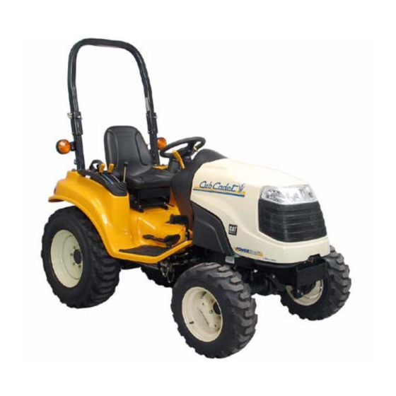
Compact tractor
Hide thumbs
Also See for Domestic Series 7000:
- Service manual (321 pages) ,
- Manual (159 pages) ,
- Owner's manual (52 pages)
Table of Contents
Advertisement
Service Manual
Domestic Series 7000 Compact Tractor
NOTE: These materials are prepared for use by trained technicians who are experienced in the service and repair of equipment of the
kind described in this publication, and are not intended for use by untrained or inexperienced individuals. Such individuals should seek
the assistance of an authorized service technician or dealer. Read, understand, and follow all directions when working on this equip-
ment. This includes the contents of the Operators Manual, which came with your equipment. No liability can be accepted for any inac-
curacies or omission in this publication, although every care has been take to make it as complete and accurate as possible. The right
is reserved to make changes at any time to this document without prior notice and without incurring an obligation to make such
changes to previously published documents. All information contained in this publication is based on product information available at
the time of publication. Photographs and illustrations used in this publication are for reference use only and may not depict actual
model and component parts.
MTD Products Inc. - Product Training and Education Department
FORM NUMBER - 769-01634
12/2004
Advertisement
Table of Contents

Related Manuals for Cub Cadet Domestic Series 7000


Summary of Contents for Cub Cadet Domestic Series 7000
- Page 1 Service Manual Domestic Series 7000 Compact Tractor NOTE: These materials are prepared for use by trained technicians who are experienced in the service and repair of equipment of the kind described in this publication, and are not intended for use by untrained or inexperienced individuals. Such individuals should seek the assistance of an authorized service technician or dealer.
-
Page 3: Table Of Contents
Dash Panel Removal ....................59 The Dash Panel ....................... 63 Steering Shaft and Pump: Sauer ................65 Steering Shaft and Pump: Ross ................67 Domestic Series 7000 Damped Driveshaft Preparation: ......................69 Driveshaft Removal ....................69 Electrical System Electrical System ...................... 72 Componants...................... -
Page 5: Domestic Series 7000 Hydraulics
1.2. Fluid: the transmission and hydraulic system are filled with 6.5 gallons (24.6 L) of Cub Cadet Hydraulic Transmission Fluid (P/N: 737-3025 Hydrostatic 1Qt., 737-3062 1Gal., 737-3063 10 Qt., 737- drive pump 3035 5 Gal.). - Page 6 Domestic Series 7000 Hydraulics 1.7. The steering pump, located in the dash pedestal 1.11. The hydraulic fluid flow is as follows: contains it’s own back-up gerotor charge pump 1.12. Through the pick-up tube from the transmission that will enable steering control when the engine sump and filter, to the auxiliary pump.
- Page 7 Domestic Series 7000 Hydraulics 1.14. The steering unit distributes pressure to the 1.16. The power steering unit is first in line, and has steering cylinder according to the position of the priority over the rest of the system. From the steering wheel.
-
Page 8: Hydrostatic Drive: Basic Operation
Domestic Series 7000 Hydraulics 1.19. If the fluid is required by the lift cylinder, it will go HYDROSTATIC DRIVE: BASIC OPERATION to the bottom port of the lift valve instead of the 2.1. The input shaft to the D15U turns a shaft that return manifold. - Page 9 Domestic Series 7000 Hydraulics 2.4. The lower part of the pump contains a fixed dis- 2.6. Tilting the swash plate the other way causes the placement axial piston hydraulic motor. The variable displacement pump to drive fluid motor is driven by the output of the variable dis- through the fixed displacement pump in the placement pump.
-
Page 10: External Checks
Inspect the assembly brake assembly. NOTE: Complete brake adjustment procedures can be found in the 2003 Cub Cadet Technical Handbook, page 6-131 through 6-133. Figure 3.2 NOTE: Complete neutral control adjustment pro- cedures can be found in the 2003 Cub Cadet... - Page 11 Check Figure 3.8 the level, and compare the fluid to a sample of Cub Cadet Hydraulic Transmission Fluid. Top- up or replace the fluid as necessary. NOTE: Drain the transmission fluid before See Figure 3.6.
-
Page 12: Best Practices: Hydraulic Systems
Remember that the front drive axle on four- NOTE: Sealants wheel drive Domestic Series 7000 tractors will engage automatically. • O-ring fittings require no sealant, though light lubrication with the fluid used in the system is sometimes helpful. - Page 13 Domestic Series 7000 Hydraulics 5.4. The charge pump should generate between 70 5.7. Assuming the supply to the pump is good, low and 150 PSI (4.8 to 10.3 Bars) @ 1,200 RPM. pressure or a complete lack of pressure at this See Figure 5.4.
- Page 14 Domestic Series 7000 Hydraulics 5.9. If the charge pump is working, but drive has 5.11. When removed, each charge relief valve comes been lost in one direction only, one of the charge out as a cartridge. See Figure 5.11. check valves may not be working.
-
Page 15: Auxiliary Pumps
• Check the fluid. If the fluid level is low, or the 6.2. Domestic Series 7000 tractors produced before fluid is not the correct type, both the hydrostat the 2004 season came with a single auxiliary and the auxiliary pump will perform poorly. - Page 16 Fender removal is detailed employs the auxiliary pump drive gear as a tone- in the 2003 Cub Cadet Technical Handbook on ring to generate a tachometer signal. This was pages 6-21 through 6-27.
- Page 17 Domestic Series 7000 Hydraulics 6.16. Disconnect the output line from the top of the • Set the throttle to maintain an engine speed in pump using a 3/4” wrench and a 9/16” wrench. this range, and note the reading on the flow meter.
-
Page 18: Steering Pump And Cylinder
If there is a warrantable problem with the power steering unit, it is to be replaced as a complete Solution 2: Internal problem; leaf spring. unit. Cub Cadet does not stock any internal components for the steering units. • Backlash 7.5. - Page 19 Domestic Series 7000 Hydraulics • Shimmy: • The Steering Wheel Does Not Return to Cen- ter: Cause 1: Air in steering system. Cause 1: There is a mechanical bind in the steering Solution 1: Repair any leaks in the hydraulic system.
- Page 20 Domestic Series 7000 Hydraulics 7.6. Engine-off test: With the engine turned-off so 7.11. Disconnect the hydraulic line between the steer- that no pressure is supplied by the auxiliary ing unit and the steering cylinder using a 5/8” pump, the pump within the steering unit should wrench and a 3/4”...
- Page 21 Domestic Series 7000 Hydraulics 7.15. Have an assistant slowly turn the steering wheel • If the test kit is attached (as illustrated in figure until the steering linkage hits the end of its travel. 7.11) to the fitting at the base end of the cylinder, Applying pressure to the steering wheel while turn the steering wheel to the right.
-
Page 22: Hydraulic Lift Cylinder And Control Valve
Domestic Series 7000 Hydraulics HYDRAULIC LIFT CYLINDER AND CON- 8.3. Orientation of the valve: See Figure 8.3. TROL VALVE Return line directly to 8.1. If the hydraulic lift cylinder does not work or is transmission housing low on power, begin by making a visual inspec- (when arms are tion of the cylinder, linkage, and feedback rod. - Page 23 8.5. Control Linkage Description: 8.9. The category 1 three point hitch system on the domestic Series 7000 tractor should be capable • The feedback rod and link assembly governs the of lifting 950 lbs. (430 Kg.), 24 in. (61 cm.) motion of the lift arms.
- Page 24 Domestic Series 7000 Hydraulics 8.16. Install the test kit with the flexible line connected 8.21. Carefully close the valve on the test kit. Do not to the pressure gauge end of the kit, and the close the valve all the way. It is not necessary to control valve connected to the flow meter end of move the lift cylinder to generate pressure.
- Page 25 Domestic Series 7000 Hydraulics 8.26. Set the parking brake, place the gear selector in 8.30. The pressure should approach but not exceed neutral, open the flow valve on the gauge set all 1,500 PSI (103 Bars). the way, and confirm that no unsafe conditions 8.31.
-
Page 26: Tandem Pump
Domestic Series 7000 Hydraulics TANDEM PUMP 9.5. Disconnect either hydraulic tube between the bracket / bulkhead fitting on the frame, and the 9.1. Attachments are covered in a separate section. loader valve. Use a 7/8” wrench and a 1” This section covers the portions of the hydraulic wrench to disconnect the tube. - Page 27 Domestic Series 7000 Hydraulics • System pressure is regulated by a relief valve in the loader valve. 9.10. Observe the flow rate. It should be in the 6.5 GPM (25 L/m) range. See Figure 9.10. • In this test, we have effectively disabled that relief valve.
-
Page 28: Loader Valve
Domestic Series 7000 Hydraulics LOADER VALVE 10.5. With the test kit installed as shown, pushing the loader valve forward to the detent will generate a 10.1. the simplest way to check pressure to the reading on the flow meter of about 6.6 GPM (25 attachment is by connecting the test kit to the L/m) when the test kit flow valve is open. - Page 29 10.9. In order to adjust the relief valve, it is necessary to remove the fenders. The fender removal pro- cess is described in detail in the 2003 Cub Cadet Figure 10.11 Technical Handbook, page 6-21 through page 6- 10.12.
-
Page 30: Component Breakdown: Auxiliary Pump (Tandem Pump Similar)
Domestic Series 7000 Hydraulics 10.13. Loosen the jam nut using a 7/8” wrench and turn COMPONENT BREAKDOWN: AUXILIARY the adjuster screw using a 7/16” wrench. PUMP (TANDEM PUMP SIMILAR) See Figure 10.13. NOTE: The auxiliary pump is to be replaced as a unit if it fails. - Page 31 Domestic Series 7000 Hydraulics 11.2. The back cover can be removed from the pump 11.7. There is a cartridge that slides into the pump by removing the four socket head cap screws. body. See Figure 11.7. See Figure 11.2. Second...
-
Page 32: Component Breakdown: Steering Unit
NOTE: Individual components of the steering unit are not available through Cub Cadet. 12.1. The fittings on the end of the steering unit extend through the first two sections of the body, into the third and largest section. - Page 33 Domestic Series 7000 Hydraulics 12.4. The cardan shaft transfers motion from the 12.6. The spool and sleeve can be easily tapped-out steering wheel, through the body of the steering of the housing. A thrust bearing assembly fits unit, to the pump. See Figure 12.4.
- Page 34 Domestic Series 7000 Hydraulics 12.8. A dowell pin connects the spool and sleeve axi- 12.10. There are two types of leaf spring: flat and ally, and transmits steering force to the sleeve bowed. A pair of each goes together, back-to- from the cardan shaft.
-
Page 35: Domestic Series 7000 Mfd
A similar appearing, but not identical MFD has been used in the Cub Cadet Series 5000 since the start of that models production. It will be mentioned in this section so that it can be distinguished from the unit used in the Series 7000. - Page 36 See Figure 1.9. Figure 1.5 1.6. The MFD produced by Cub Cadet for the four wheel drive Series 7000 tractors is part number 618-0484. The Cub Cadet Series 7000 MFD (618-0484) uses many of the same castings as the Cub Cadet Series 5000 MFD (618-0428).
-
Page 37: Mfd Removal: Preparation
Domestic Series 7000 MFD 1.10. The difference in widths is accounted for by the MFD REMOVAL: PREPARATION fact that axle flanges protrude visibly further out NOTE: This procedure can be done on tractors of the housing on the 618-0428 (5000 MFD) that are equipped with cutting decks, front-end than they do on the 618-0484 (7000 MFD). -
Page 38: Removal
Domestic Series 7000 MFD REMOVAL 3.5. Remove the four bolts holding the steering cylin- der bracket to the MFD housing using a 19 mm 3.1. Loosen the set screw that secures the back end wrench. See Figure 3.5. of the 4 W.D. drive shaft to the splined output shaft on the front of the transmission. - Page 39 Domestic Series 7000 MFD 3.8. Lift and support the front of the tractor by the dif- 3.12. Remove the four nuts that secure the front axle ferential housing. Leave the hydraulic jack in bracket to the frame using a pair of 3/4”...
-
Page 40: Mfd Installation
4.8. Remove the fill plugs from the final drive hous- ings. Fill each housing to the bottom of the fill plug hole with Cub Cadet 85W140 Gear Lube (P/N: 737-3065 for 1 qt.). Install the fill plugs. 4.9. Remove the oil level gauge from the main hous-... -
Page 41: In-Frame Repairs: Drop Axle Service
Lubricate the shoulder of the steering cylinder NOTE: Within the warranty period of the stud with grease. domestic Series 7000 tractor, repairs to the MFD will be accomplished by replacement of the com- • Apply a small amount of thread locking com- plete assembly. -
Page 42: In-Frame Repairs: Drop Axle Cover
Domestic Series 7000 MFD IN FRAME REPAIRS: DROP AXLE COVER 6.5. The inner axle bearing is a slip fit on the axle. It can be removed with light pressure on the bear- 6.1. If there is an obvious problem within the drop ing, or (preferably) by lifting the axle bevel gear. - Page 43 Domestic Series 7000 MFD 6.8. After the axle is separated from the bearing and 6.10. To reassemble the axle cover: See Figure 6.10. cover, the bearing, and the seal that protects it may be easily removed from the cover. Seal driver See Figure 6.8.
-
Page 44: In-Frame Repairs: Drop-Axle Removal
Domestic Series 7000 MFD IN-FRAME REPAIRS: DROP-AXLE REMOVAL 7.5. Lift the steering arm off of the kingpin housing and the stud for the steering cylinder. 7.1. The drop axle assembly can also be removed See Figure 7.5. complete. Stub shaft bearing 7.2. - Page 45 Domestic Series 7000 MFD 7.9. The drop axle housing can then be pushed down 7.12. Support the drop axle housing, and separate it off of the kingpin housing with some twisting and from the axle housing. See Figure 7.12. light force. See Figure 7.9.
-
Page 46: Bench Repairs: Drop Axle And Kingpin Housing Assemblies
Domestic Series 7000 MFD 7.15. To remove the bearing it may help to slide the 8.4. With the kingpin shaft removed, the 14 tooth axle shaft out roughly 1/4” (6mm). Once suffi- bevel gear can be removed. See Figure 8.4. - Page 47 Domestic Series 7000 MFD 8.6. To disassemble the drop axle housing, fixture it 8.11. Carefully pry the gear and bearing out of the in a soft-jaw vise. bore at the base of the drop axle housing. See Figure 8.11. 8.7.
- Page 48 Domestic Series 7000 MFD 8.14. Carefully press the 13 tooth pinion bevel gear 8.18. Install the two seals above the tapered roller into the bearing that carries it. Use care to iso- bearing using an appropriate driver. late pressing force to the inner race of the bear- See Figure 8.18.
- Page 49 Domestic Series 7000 MFD 8.21. Install the kingpin shaft in the kingpin housing. • Apply a small amount of thread locking com- The end of the shaft with the pilot nose should pound such as Loctite 242 (blue) to the threads engage the 14 tooth bevel gear.
-
Page 50: Bench Repair: Axles And Differential
Domestic Series 7000 MFD BENCH REPAIR: AXLES AND DIFFEREN- 9.5. Remove both drop-axle housings using a 17 mm TIAL. wrench. See Figure 9.5. 9.1. Remove the MFD complete, as described in the Drop axle housing separated “REMOVAL” section of this manual. - Page 51 Domestic Series 7000 MFD 9.9. Separating the housings is best done in a verti- 9.12. With the differential bearing removed, the 16 cal position. After the sealant between the two tooth miter gear can be lifted out of the differen- housings is broken, securely stand the assembly tial housing.
- Page 52 Domestic Series 7000 MFD 9.15. The shim washers and inner axle bearing can be 9.18. After the nut is de-staked, use the front wheel easily removed from the right side axle hous- drive shaft to hold the pinion shaft, while tuning ing.
- Page 53 Domestic Series 7000 MFD 9.21. Remove the spacer that fits between the pinion 9.23. If the pinion bearings are suspect, drive the shaft and the seal. See Figure 9.21. outer races from the pinion bore as well. Keep the races associated with the same bearings that originally ran in them.
- Page 54 Domestic Series 7000 MFD 9.27. With the cross pin removed, the 10 tooth miter 9.30. Clean and inspect all components. gears, and the spherical thrust bearings that fit • Replace all of the seals and o-rings. behind them can be removed. See Figure 9.27.
- Page 55 Domestic Series 7000 MFD 9.33. Drive new outer races into place if the pinion 9.40. Install the axle shaft, inner and outer axle bear- bearings have been replaced. ings, washer, and 14 tooth bevel gear, into the right side axle housing. See Figure 9.40.
- Page 56 Domestic Series 7000 MFD 9.42. The final assembly is easiest to perform with the 9.44. Place the differential assembly into the right side axle housing in a vertical position. axle housing. See Figure 9.44. See Figure 9.42. Roll pin Cross...
- Page 57 Domestic Series 7000 MFD 9.46. Position the differential set-up plate tool over the 9.49. If it is necessary to remove the differential to add dowel pins and differential bearing. or remove washers, the axle shaft must be held See Figure 9.46.
- Page 58 Domestic Series 7000 MFD 9.51. To determine the amount of shimming necessary 9.53. Position the left side axle bearing and axle in the to maintain .003”-.010” (.076-.254 mm) end play, differential. The shim washers should be it is necessary to intentionally over-shim, creat- between the differential bearing and the bearing ing a gap between the left and right housings.
- Page 59 Domestic Series 7000 MFD 9.57. Apply a small amount of threadlocking com- 9.62. Install the drop axle and secure it with the four pound such as Loctite 242 (blue) to the threads bolts. Tighten the bolts to a torque of 220-280 of the 8 bolts used to fasten the left and right in-lbs.
- Page 60 Domestic Series 7000 MFD 9.67. Use the front wheel drive shaft to hold the pinion 9.70. Install the washers and nut. tighten them until shaft, while using a 1 1/4” wrench to loosen the the match marks made previously align.
-
Page 61: Torque Specifications
Domestic Series 7000 MFD TORQUE SPECIFICATIONS 9.73. Install the MFD in the tractor as described in the MFD INSTALLATION section of this manual. Item Torque SAE Torque Metric Loctite Ring Gear Bolts 160-220 in-lbs 18-25 Nm 242 blue Perimiter Bolts (axle housing) - Page 62 Domestic Series 7000 MFD...
-
Page 63: Domestic Compact Dash And Steering Pump
Domestic Compact Dash and Steering Pump Domestic Compact Dash and Steering Pump ABOUT THIS SECTION: 1.4. The switches can be removed by squeezing the tabs on the short sides of the switch body, and The parking brake linkage, throttle lever and cable, pushing them up through the dash panel. - Page 64 Domestic Compact Dash and Steering Pump 1.6. Use a pair of 1/2” wrenches to loosen the bolts 1.11. There is a shoulder bushing and flat washer on flanking the instrument panel on the inside of the the steering shaft. They provide support for the dash panel.
- Page 65 Domestic Compact Dash and Steering Pump 1.14. On Briggs & Stratton / Daihatsu engines, a Z-fit- 1.16. Remove the two phillips head screws that ting connects the cable to the pump. An 8mm secure the lower rear corners of the dash panel. wrench will fit the screw on the cable clamp.
- Page 66 Domestic Compact Dash and Steering Pump 1.20. Carefully lift the dash panel and remove it from 1.23. The choke cable on gasoline engined tractors the tractor. Confirm that the wiring harness and passes through the large opening in the pedes- control cables do not snag as they pull out with tal, below and to the left of the steering column the dash panel.
-
Page 67: The Dash Panel
Domestic Compact Dash and Steering Pump 1.28. Connect the choke and throttle control cables in THE DASH PANEL the slack position. 2.1. The primary reason to remove the dash panel 1.29. On gasoline powered tractors: would be to gain access to the following items: •... - Page 68 Domestic Compact Dash and Steering Pump 2.4. The throttle cable can be removed from the 2.7. The throttle assmebly can be unbolted fromt he throttle assembly by squeezing the barbs on the dash panel using a 7/16” wrench. cable end. See Figure 2.7.
-
Page 69: Steering Shaft And Pump: Sauer
Domestic Compact Dash and Steering Pump STEERING SHAFT AND PUMP: SAUER 3.4. Remove the hairpin clip and clevis pin that secure the brake lever bracket to the steering 3.1. Identification: Series 7000 tractors built before column bracket. The steering shaft passes the 2004 model year are equipped with a Sauer through the brake lever bracket. - Page 70 Domestic Compact Dash and Steering Pump 3.9. Place a drain pan under the steering pump. 3.12. The ports are labeled on the bottom of the steer- ing pump. See Figure 3.12. 3.10. Working from back to front, disconnect the hydraulic lines fromthe steering pump. Cap the NOTE: O-ring adaptors lines as they are removed.
-
Page 71: Steering Shaft And Pump: Ross
Domestic Compact Dash and Steering Pump STEERING SHAFT AND PUMP: ROSS 4.4. Remove the hairpin clip and clevis pin that secure the brake lever bracket to the steering 4.1. Series 7000 tractors built during and after the column bracket. The steering shaft passes 2004 model year, and all 5000 series tractors through the brake lever bracket. - Page 72 Domestic Compact Dash and Steering Pump 4.7. After the lines are disconnected, and the lines 4.11. At the technician’s discretion, the retaining ring and fittings are capped, remove the nuts that securing the steering shaft to the steering col- secure the steering pump to the pump mounting umn bracket can be removed, and the two parts bracket using a 1/2 wrench.
-
Page 73: Domestic Series 7000 Damped Driveshaft
Domestic Series 7000 Damped Driveshaft ABOUT THIS SECTION: DRIVESHAFT REMOVAL Domestic Cub Cadet Series 7000 tractors equipped 2.1. Loosen the two clamp bolts on the rear drive- with the Caterpillar diesel engine may exhibit an objec- shaft yoke using a pair of 9/16” wrenches. - Page 74 Domestic Series 7000 Damped Driveshaft 2.3. Slide the back end of the driveshaft off of the 2.6. Slide the engine as far forward as possible. The splined input shaft on the hydrostatic drive, and left side of the engine goes slightly farther than remove the driveshaft.
- Page 75 Domestic Series 7000 Damped Driveshaft 2.10. Slide the replacement driveshaft into position. 2.14. Prevent the flywheel from turning using a fly- the flange should nest into the recess in the fly- wheel tool or by blocking the driveshaft, and wheel.
-
Page 76: Electrical System Electrical System
Domestic Series 7000 Damped Driveshaft... - Page 77 This part of the manual provides verbal descriptions of engine. the function of each electrical component in the sys- tem. It is best used to compliment the Cub Cadet Wir- 1.9. Diesel engines will have a stop solenoid on the...
-
Page 78: Componants
Domestic Compact Electrical Systems 1.11. The gasoline engines use flywheel mounted 1.14. As with all electrical systems, do not neglect the rotors and engine mounted stators to generate basics: clean connections and good ground A.C. current. The current is processed through paths. - Page 79 Domestic Compact Electrical Systems 2.2. Behind the access panel is a fuse center. 2.4. Diesel powered tractors will have the following See Figure 2.2. components at the right rear corner of the engine bay: • A single relay to power the glow-plug circuit. (P/N: 725-04164) •...
- Page 80 Domestic Compact Electrical Systems 2.6. Kohler powered tractors use a similar engine kill 2.7. Located on the dash panel are the hazard relay arrangement. See Figure 2.6. flasher switch, light switch, PTO switch, Key switch, and instrument panel. See Figure 2.7. Kill relay Lights Hazard...
- Page 81 Domestic Compact Electrical Systems 2.9. The hazard flasher draws constant hot through 2.10. The PTO switch is more complex. the red wire with white trace. See Figure 2.9. See Figure 2.10. Headlight Hazard flasher switch switch PTO switch Figure 2.9 Figure 2.10 •...
- Page 82 Domestic Compact Electrical Systems 2.11. The key switch has four spade terminals. 2.13. The pin numbers are indicated on the molded See Figure 2.11. connector. See Figure 2.13. back row: # 16 -> # 23 center row: # 9 -> # 15 “16”...
- Page 83 Domestic Compact Electrical Systems 2.15. The pin identities are as follows: 2.17. On Series 6000 and domestic Series 7000, there See Figure 2.15. are four wires to the switch. See Figure 2.17. P in -o u t ch art P in...
- Page 84 Domestic Compact Electrical Systems 2.19. The fuel tank sender unit also lives under the 2.21. The reverse switches differ between the Series fender, on the left hand side. It is basically a 5000 tractor and the other domestic compact potentiometer actuated by a float. It creates tractors.
-
Page 85: Eelstric Clutch And Fuel Pump
Domestic Compact Electrical Systems 2.22. The reverse switch on the series 6000 and 7000 2.24. The brake switch on the Series 5000 tractor con- tractors operates in the same manner to control tains three sets of contacts. See Figure 2.24. the PTO clutch. - Page 86 The electric PTO clutch on the Series 6000 and has two sets of contacts. It is mounted to the domestic Series 7000 compact tractors is con- right hand side frame channel, in front of the tained inside the transaxle. The wire that pro- pedal linkages.
- Page 87 Domestic Compact Electrical Systems 3.2. The Electric PTO clutch on Series 5000 compact 3.3. The electric fuel pump is mounted to the left tractors is external, but requires some transaxle hand side frame channel on all gasoline pow- disassembly to remove. See Figure 3.2. ered domestic compact tractors.
- Page 88 Domestic Compact Electrical Systems...