Table of Contents
Advertisement
Quick Links
Operator's Manual
IMPORTANT: READ SAFETY RULES AND INSTRUCTIONS CAREFULLY
Warning
: This unit is equipped with an internal combustion engine and should not be used on or near any unimproved
forest-covered, brush-covered or grass-covered land unless the engine's exhaust system is equipped with a spark
arrester meeting applicable local or state laws (if any). If a spark arrester is used, it should be maintained in effective
working order by the operator. In the State of California the above is required by law (Section 4442 of the California Public
Resources Code). Other states may have similar laws. Federal laws apply on federal lands. A spark arrester for the
muffler is available through your nearest engine authorized service dealer or contact the service department, P.O. Box
361131 Cleveland, Ohio 44136-0019.
CUB CADET LLC P.O. BOX 361131 CLEVELAND, OHIO 44136-0019 [www.cubcadet.com]
PRINTED IN U.S.A.
S
ERIES
TRACTOR
MODEL 5264D
5000
FORM NO. 769-01947
(11/05)
Advertisement
Table of Contents

Related Manuals for Cub Cadet 5264D


Summary of Contents for Cub Cadet 5264D
- Page 1 P.O. Box 361131 Cleveland, Ohio 44136-0019. CUB CADET LLC P.O. BOX 361131 CLEVELAND, OHIO 44136-0019 [www.cubcadet.com] PRINTED IN U.S.A. 5000 ERIES TRACTOR MODEL 5264D FORM NO. 769-01947 (11/05)
-
Page 2: Table Of Contents
TABLE OF CONTENTS TO THE OWNER ... 2 CALLING SERVICE INFORMATION ... 2 RECORDING MODEL AND SERIAL NUMBER INFORMATION ... 3 IMPORTANT SAFE OPERATION PRACTICES ... 4 SAFETY LABELS ... 8 SECTION 1: CONTROLS AND FEATURES ... 9 SECTION 2: OPERATION ... 14 SECTION 3: ADJUSTMENTS ... -
Page 3: Recording Model And Serial Number Information
RECORDING MODEL AND SERIAL NUMBER INFORMATION Product identification plates are provided for major components of your tractor. The numbers on these plates are important if your tractor should require dealer service, or if you need additional information on your tractor. Prior to using your tractor for the first time, record the numbers from the identification plates in the appropriate spaces provided below. -
Page 4: Important Safe Operation Practices
IMPORTANT SAFE OPERATION PRACTICES WARNING: THIS SYMBOL POINTS OUT IMPORTANT SAFETY INSTRUCTIONS WHICH, IF NOT FOLLOWED, COULD ENDANGER THE PERSONAL SAFETY AND/OR PROPERTY OF YOURSELF AND OTHERS. READ AND FOLLOW ALL INSTRUCTIONS IN THIS MANUAL BEFORE ATTEMPTING TO OPERATE YOUR UNIT. FAILURE TO COMPLY WITH THESE INSTRUCTIONS MAY RESULT IN PERSONAL INJURY. -
Page 5: Slope Operation
• Disengage all attachment clutches, thoroughly depress the brake pedal and shift into neutral before attempting to start the engine. • Your mower is designed to cut normal residential grass of a height no more than 10”. Do not attempt to mow through unusually tall, dry grass (e.g. -
Page 6: Operating The Pto
3. CHILDREN • Tragic accidents can occur if the operator is not alert to the presence of children. Children are often attracted to the machine. Never assume children will remain where you last saw them. • Keep children out of the mowing area and in watchful care of an adult other than the operator. - Page 7 • Keep all nuts, bolts and screws tight to be sure the equipment is in safe working condition. • Never tamper with safety devices. Check their proper operation regularly. • After striking a foreign object, stop the engine, and thoroughly inspect the mower for any damage.
-
Page 8: Safety Labels
SAFETY LABELS WARNING AVOID SERIOUS INJURY OR DEATH GO UP AND DOWN SLOPES, NOT ACROSS. AVOID SUDDEN TURNS. DO NOT OPERATE UNIT WHERE IT COULD SLIP OR TIP. IF MACHINE STOPS GOING UPHILL, STOP PTO AND BACK DOWN HILL SLOWLY. DO NOT MOW WHEN CHILDREN OR OTHERS ARE AROUND. -
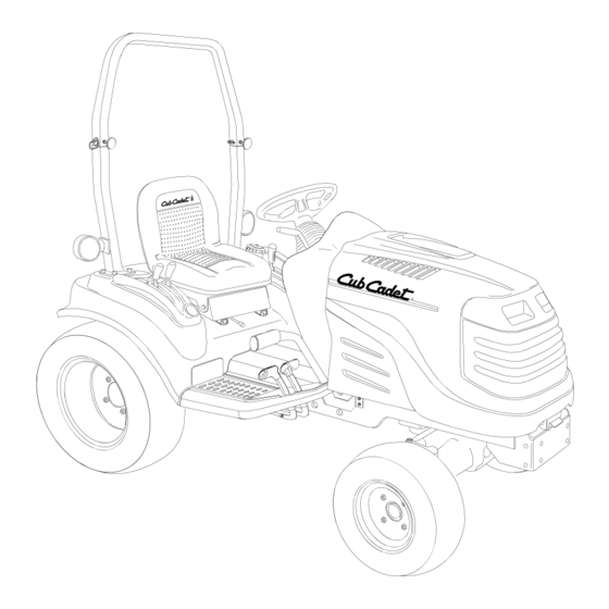
Page 9: Section 1: Controls And Features
SECTION 1: CONTROLS AND FEATURES Steering Wheel Throttle Handle PTO Switch Ignition Switch Brake Pedal Reverse Pedal G. Forward Pedal H. Hand Holds * Steering Wheel, Seat, and ROPS Transparent for Clarity HOURS 1/10 FUEL x1000 Figure 1 Trans. 4WD Shift Lever Hydraulic Lift Lever Cup Holder Amber Hazzard Light... - Page 10 NOTE: References to LEFT and RIGHT indicate that side of the tractor when facing forward while seated in the drivers seat. Reference to FRONT indicates the grille end of the tractor; to REAR, the tow plate end. A. Steering Wheel The steering wheel is centered on the dash panel, and used to change the direction (left or right) of the tractor while driving.
- Page 11 H. Hand Holds Hand holds are built into both the left and right hand fender covers. The handles can be used to assist in mounting and dismounting the tractor. J. Transmission 4WD Shift Lever The 4WD shift lever is located on the right fender. This lever is used to engage the transmission drive that powers the front transaxle.
- Page 12 T. Differential Lock Pedal Diff. Lock Pedal Symbol Figure 8 Located at the front of the left running board, the differential lock pedal engages the transmission differential lock. The differential lock is used to gain additional trac- tion when operating the tractor on wet or loose soil. When the pedal is depressed the rear wheels of the tractor are prevented from rotating independently of one another.
- Page 13 X. Instrument Panel 1. Fuel Gauge The fuel gauge monitors the fuel level in the fuel tank. The needle pointing to the right indicates a full tank. The ignition switch must be in the ON position to activate the fuel gauge. 2.
-
Page 14: Section 2: Operation
SECTION 2: OPERATION ROLLOVER PROTECTIVE STRUCTURE (ROPS) This tractor is equipped with a foldable Rollover Protection Structure (ROPS) and seat belts. When used together they are effective in reducing injuries to the operator in the event of an accidental tractor rollover. - Page 15 lock is engaged. NOTE: The PTO switch must be moved to the “OFF” position to restart the engine. • The safety interlock system will shut off the PTO if the reverse control pedal is depressed, unless reverse override activated. NOTE: If the reverse override function has been activated, it will remain activated until the ignition switch is turned to the "OFF"...
- Page 16 • Turn the ignition key clockwise to the "RUN- PREHEAT" position, and observe the glow plug indicator light on the instrument panel. Wait until the glow plug indicator light turns off before cranking the engine. NOTE: Preheating may not be necessary if the engine has been running and is warm.
- Page 17 STOPPING THE TRACTOR • Fully depress the brake pedal to bring the trac- tor to a complete stop. Push downward on the parking brake lever and release the pedal to engage the parking brake. Refer to Figure 15. • Depress the rear of the PTO switch to disengage the PTO.
- Page 18 DRIVING ON SLOPES WARNING: Do not operate on inclines with a slope in excess of 15 degrees (a rise of approximately 2-1/2 feet every 10 feet). The tractor could overturn and cause serious injury. IMPORTANT: Always shift into LOW speed range before beginning to climb or descend a slope.
- Page 19 USING THE HYDRAULIC LIFT LEVER The hydraulic lift system provides power for raising and positioning three point hitch and belly mounted equipment. To raise an attachment using the hydraulic lift system, the engine must be running. Generally, an attachment can be lowered with the engine running or off.
- Page 20 Hazard Lights Always use the flashing amber hazard lights along with the SMV (Slow Moving Vehicle) emblem when operating the tractor on, or near, roadways. Also activate the hazard lights when necessary to warn others that the tractor is being operated in the area. •...
- Page 21 USING THE HITCH PLATE Use only the hitch plate (Refer to Figure 23), for towing pull-behind equipment (carts, trailers, etc.) or dragging loads. Raise the lower links of the three point hitch to their highest position to prevent interference with the towed equipment.
-
Page 22: Section 3: Adjustments
SECTION 3: ADJUSTMENTS ADJUSTING THE SEAT For the comfort of the operator, a single lever adjustable seat is provided to set the fore to aft position of the seat. Adjust the seat to the most comfortable position that allows you to operate all controls and pedals. - Page 23 • The length of the upper hitch link is normally determined by the design of each implement. To adjust the upper hitch link, loosen the lock- ing lever and turn the adjustment tube as shown in Figure 27. After the appropriate length is attained, tighten the locking lever.
- Page 24 ADJUSTING THE BRAKES The tractor brakes are adjusted at the factory and should experience minimal wear if the tractor is operated normally. However, all brake pads are subject to wear and at some point the brake linkage may have to be adjusted. Check the brakes as follows: •...
-
Page 25: Section 4: Tractor Maintenance
SECTION 4: MAINTENANCE The service life and reliability of any machine depends upon the care it is given. Proper lubrica- tion and maintenance is a vital part of that care. Using the Lubrication and Maintenance Chart as a guide, monitor the hourmeter on the instrument panel to ensure the required maintenance proce- dures are performed. - Page 26 LUBRICATION AND MAINTENANCE CHART (ILLUSTRATION)
-
Page 27: Lubrication And Maintenance Chart
LUBRICATION AND MAINTENANCE CHART Ref. Operation to be Performed Check Engine Oil Level Check Air Cleaner Check Engine Coolant Level Check and Clean Radiator Screen Change Engine Oil and Replace Oil Filter Retorque Front and Rear Wheel Lug Nuts Check Transmission Oil Level Replace Hydrostatic Transmission Oil Filter Replace Hydraulic System Filter... - Page 28 ACCESSING THE ENGINE COMPARTMENT WARNING: If the tractor has been recently operated, engine surfaces (including the radiator) will be HOT. Allow the engine to cool before open- ing the hood, or use extreme caution to avoid burns when the hood is open. To raise the hood, locate the hood latch below the hood notch at the front of the tractor.
- Page 29 BATTERY REMOVAL WARNING: Battery posts, terminals and related accessories contain lead and lead compounds. Wash hands after handling. The battery is located at the front of the tractor beneath the hood. To remove the battery: • Open the tractor hood as described in the previous sub-section.
- Page 30 • Turn the bulb/socket assembly approximately a quarter turn counterclockwise to align its tabs with the notches of the reflector, then remove from the reflector. WIRE HARNESS PLUG BULB/SOCKET ASSEMBLY Figure 35 • Replace with a new bulb/socket assembly (Cub Cadet No.
- Page 31 Accessing the Lower Dash Panel Area Some electrical components are housed inside the lower dash panel. To access the area, remove the dash panel insert by removing the two screws. See Figure 39. Figure 39 To reinstall the dash panel insert, hook the retaining lip at the bottom of the insert over the bottom edge of the dash opening, pivot the insert upward into position, and secure with the two screws.
-
Page 32: Checking Transmission/Hydraulic System Oil Level
CHECKING TRANSMISSION/HYDRAULIC SYSTEM OIL LEVEL Check the hydro transmission/hydraulic system oil level before each use. NOTE: Check the oil level only while the engine is stopped and the tractor is standing on a level surface. The oil level sight glass is located in the rear of the transmission housing, just to the right of the rear PTO shaft. - Page 33 • Remove the old hydrostatic filter by turning it counterclockwise, and immediately replace with the new filter. Turn the filter clockwise by hand until the gasket contacts the filter base; then tighten the filter an additional 1/2 to 3/4 turn. •...
- Page 34 Dispose of used oil in an environmentally safe manner. If necessary, contact your area EPA office for proper disposal proce- dures and recycling center locations. • Change the hydro transmission instructed in Changing Hydro Transmission Oil Filter. • Change the hydraulic system filter as instructed in Changing Hydraulic System Oil Filter.
- Page 35 • To prevent debris from entering the front axle housing, clean the area around the oil fill plug/ dipstick and the axle drain plug located at the center front of the axle. Refer to Figure 45 and Figure 47. FRONT AXLE DRAIN PLUG Figure 47 •...
- Page 36 TIRE MAINTENANCE Check the tire air pressure after every 50 hours of operation or weekly. Keep the tires inflated to the recommended pressures. Improper inflation will shorten the service life of a tire. See the tire side wall, or the Tire Inflation chart, for proper inflation pressures.
- Page 37 TRACTOR STORAGE If your tractor is not going to be operated for an extended period of time (thirty days to approxi- mately six months), the tractor should be prepared for storage. Store the tractor in a dry and protected location. If stored outside, cover the tractor (includ- ing the tires) to protect it from the elements.
-
Page 38: Section 5: Engine Information And Maintenance
SECTION 5: ENGINE INFORMATION AND MAINTENANCE Daihatsu L.L.C., the California Air Resources Board (CARB) and the United States Environmental Protection Agency (U.S. EPA) (Owner’s Defect Warranty Rights and Obligations) EMISSION CONTROL WARRANTY COVERAGE IS APPLICABLE TO CERTIFIED MODEL YEAR 2001 AND LATER ENGINES, WHICH ARE PURCHASED AND USED IN CALIFORNIA, AND TO CERTIFIED MODEL YEAR 2001 AND LATER ENGINES WHICH ARE PURCHASED AND USED ELSEWHERE IN THE UNITED STATES California And United States Emission Control Defects Warranty Statement... - Page 39 c. Ignition System • Glow plug d. Exhaust System • Exhaust manifold e. Miscellaneous Items Used in Above Systems • Vacuum, temperature, position, time sensitive valves and switches • Electronic controls • Connectors and assemblies • Hoses Length of Coverage — Daihatsu warrants to the initial owner and each subsequent purchaser that the Warranted Parts shall be free from defects in materials and workmanship which caused the failure of the Warranted Parts for a period of 1,500 hours or two years, whichever occurs first, from the date the engine is delivered to a retail purchaser.
- Page 40 ENGINE MAINTENANCE WARNING: Use care when servicing any component in the engine area. If the engine has recently been operated, components will be hot and could cause burns. Allow the engine to cool before servicing. WARNING: Before servicing the engine, place the tractor on a level surface, stop the engine, engage the parking brake, and remove the key from the...
- Page 41 • Clean the area around the oil filler cap to prevent debris from entering the crankcase. See Figure 51. Figure 51 • Turn the oil filler cap counterclockwise to unscrew from the valve cover. • SLOWLY pour oil into the crankcase until the oil level reaches the “FULL”...
- Page 42 • Start the engine and run for about 5 minutes. Stop the engine and check for leaks at the oil filter and drain plug. • Wait 3 minutes and re-check the oil level. If needed, add oil to bring the oil level up to the "FULL"...
- Page 43 • Place a suitable container beneath the drain plug and remove the cap from the overflow reservoir. • Turn the drain plug counterclockwise to re- move. Allow as much of the old coolant as pos- sible to drain from the system. Coolant is a toxic substance.
- Page 44 SERVICING THE FUEL FILTER WARNING: Do not service the fuel filter when tractor is hot or near any source of ignition. Allow the tractor to cool. The tractor is equipped with an in-line fuel filter located on the right side of the engine. Diesel fuel is a toxic substance.
-
Page 45: Section 6: Specifications
SECTION 6: SPECIFICATIONS Engine Manufacturer............Diahatsu Horsepower . -
Page 46: Specifications
SPECIFICATIONS Hydraulic Lift System Type ............Auxiliary Pump Control . -
Page 47: Section 7: Optional Equipment And Accessories
SECTION 7: OPTIONAL EQUIPMENT AND ACCESSORIES When purchasing your tractor, you probably had it equipped for your particular needs at that time. You may later wish to obtain additional equipment or accessories to perform other tasks. Refer to the chart below for a list of optional equipment and accessories currently available through your Cub Cadet dealer. -
Page 48: Warranty
Proper maintenance of your Cub Cadet equipment is the owner’s responsibility. Follow the instructions in your owner’s manual for correct lubricants and maintenance schedule. Your Cub Cadet dealer carries a complete line of genuine Cub Cadet parts and quality lubricants and filters for your equipment’s engine, transmission, chassis and attachments. This limited warranty covers any defect in materials or workmanship in your Cub Cadet compact tractor and Cub Cadet attachments from the date of purchase for the first user purchaser.