Table of Contents
Advertisement
Quick Links
EMPIRE
EMPIRE
Comfort Systems
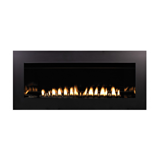
CONTEMpORARY LINEAR
vENT-FREE FIREpLACE
Installer:
Leave this manual with the appliance.
Consumer: Retain this manual for future reference.
WARNING: If the information in these instructions
are not followed exactly, a fire or explosion may
result causing property damage, personal injury
or loss of life.
— Do not store or use gasoline or other flammable
vapors and liquids in the vicinity of this or any
other appliance.
— WHAT TO DO IF YOU SMELL GAS
•
Do not try to light any appliance.
•
Do not touch any electrical switch; do not use
any phone in your building.
•
Immediately call your gas supplier from a
neighbor's phone. Follow the gas supplier's
instructions.
•
If you cannot reach your gas supplier, call the
fire department.
— Installation and service must be performed by a
qualified installer, service agency or the gas sup-
plier.
INSTALLATION INSTRUCTIONS
AND OWNER'S MANUAL
UNvENTED
GAS FIREpLACE
MODELS
vFLL38Fp30L(N,p)-1
vFLL38Fp90L(N,p)-1
GAS-FIRED
UL FILE NO. MH46389
This appliance may be installed in an aftermarket,
permanently located, manufactured (mobile) home,
where not prohibited by local codes.
This appliance is only for use with the type of gas
indicated on the rating plate. This appliance is not
convertible for use with other gases.
This is an unvented gas-fired heater. It uses air (oxy-
gen) from the room in which it is installed. Provisions
for adequate combustion and ventilation air must be
provided. Refer to pages 10 and 11.
WARNING: If not installed, operated and maintained
in accordance with the manufacturer's instructions,
this product could expose you to substances in fuel
or from fuel combustion which can cause death or
serious illness.
WATER vApOR: A BY-pRODUCT OF UNvENTED ROOM
HEATERS
Water vapor is a by-product of gas combustion. An
unvented room heater produces approximately one (1)
ounce (30ml) of water for every 1,000 BTU's (.3KW's)
of gas input per hour. Refer to page 10.
Page 1
Advertisement
Table of Contents
Troubleshooting

Related Manuals for Empire Comfort Systems VFLL38FP30L-1


Summary of Contents for Empire Comfort Systems VFLL38FP30L-1
- Page 1 INSTALLATION INSTRUCTIONS EMPIRE EMPIRE AND OWNER'S MANUAL Comfort Systems UNvENTED CONTEMpORARY LINEAR GAS FIREpLACE vENT-FREE FIREpLACE MODELS vFLL38Fp30L(N,p)-1 vFLL38Fp90L(N,p)-1 GAS-FIRED UL FILE NO. MH46389 This appliance may be installed in an aftermarket, Installer: Leave this manual with the appliance. permanently located, manufactured (mobile) home, Consumer: Retain this manual for future reference. where not prohibited by local codes.
-
Page 2: Table Of Contents
TABLE OF CONTENTS SECTION pAGE IMPORTANT SAFETY INFORMATION ................3 SAFETY INFORMATION FOR USERS OF LP-GAS ............4 IMPORTANT INSTALLATION GUIDELINES ..............5 INTRODUCTION ....................... 6 SPECIFICATIONS ......................7 FIREPLACE DIMENSIONS ....................8 BUILT-IN FIREPLACE INSTALLATION ................9 WATER VAPOR: A BY-PRODUCT OF UNVENTED ROOM HEATERS ......10 PROVISIONS FOR ADEQUATE COMBUSTION &... -
Page 3: Important Safety Information
IMpORTANT SAFETY INFORMATION • you must operate heater with fireplace screen closed in DANGER: Indicates a hazardous situation which, if not place. Do not close glass doors while operating heater. avoided, will result in death or serious injury. • Do not place trash, logs or other articles on the log set WARNING: Indicates a hazardous situation which, if not during operation. avoided, could result in death or serious injury. •... -
Page 4: Safety Information For Users Of Lp-Gas
SAFETY INFORMATION FOR USERS OF Lp-GAS Propane (LP-Gas) is a flammable gas which can cause fires point with the members of your household. someday when and explosions. In its natural state, propane is odorless and there may not be a minute to lose, everyone's safety will depend colorless. you may not know all the following safety precau- on knowing exactly what to do. If, after reading the following tions which can protect both you and your family from an information, you feel you still need more information, please accident. Read them carefully now, then review them point by contact your gas supplier. Lp-GAS WARNING ODOR If a gas leak happens, you should be able to smell the gas because of the odorant put in the LP-Gas. That's your signal to go into immediate action! • Do not operate electric switches, light matches, use your •... -
Page 5: Important Installation Guidelines
IMpORTANT INSTALLATION GUIDELINES Proper Primary Airflow into Burner For proper burner operation and flame appearance, the flow of primary air into the venturi tube, located on the rear of the burner, must not be reduced. This flow of air is reduced if dirt, lint or other obstructions build-up around or inside the venturi. -
Page 6: Introduction
INTRODUCTION Notice: During initial firing of this unit, its paint will bake out, and Instructions to Installer smoke will occur. To prevent triggering of smoke alarms, ventilate Installer must leave instruction manual with owner after the room in which the unit is installed. installation. -
Page 7: Specifications
SpECIFICATIONS Accessories for vFLL38Fp30 (Millivolt) Models vFLL38Fp30L(N,p) Remote Control Description Input Btu/hr Maximum 38,000 38,000 Accessories Btu/hr Minimum 29,000 25,000 FRBTC Battery Operated Remote Control with Orifice 1.80mm Thermostat Air Shutter Opening FULL OPEN 1/8" FRBTP Battery Operated Programmable Remote vFLL38Fp90L(N,p) Control Input Btu/hr Maximum 38,000... -
Page 8: Fireplace Dimensions
FIREpLACE DIMENSIONS When planning a fireplace insert installation, it’s necessary to • Electrical supply requirements for optional light. determine: (120V, 60Hz, 1 Amp) (right side entrance) • Gas supply piping (left side entrance). • Proper opening size of fireplace required for installation of •... -
Page 9: Built-In Fireplace Installation
BUILT-IN FIREpLACE INSTALLATION In planning the installation for the fireplace, determine where the Four corners of the fireplace so contact is made on all four unit is to be installed and whether optional accessories are desired. perimeter edges on the bottom of the unit. Gas supply piping should also be planned at this time. -
Page 10: Water Vapor: A By-Product Of Unvented Room Heaters
WATER vApOR: A BY-pRODUCT OF UNvENTED ROOM HEATERS Water vapor is a by-product of gas combustion. An unvented room The following steps will help insure that water vapor does not heater produces approximately one (1) ounce (30ml) of water for become a problem. -
Page 11: Provisions For Adequate Combustion & Ventilation Air
pROvISIONS FOR ADEqUATE COMBUSTION & vENTILATION AIR (continued) Ventilation Air From Outdoors The space in the above example is a confined space because the Provide extra fresh air by using ventilation grills or ducts. You must actual BTU/Hr used is more than the maximum BTU/HR the space provide two permanent openings: one within 12"... -
Page 12: Gas Supply
GAS SUppLY The gas pipeline can be brought in through the right or left side of Installing the Main Gas Cock the appliance. The insert has a Flexline with shutoff valve located Each appliance should have its own manual gas cock. on the right side when facing the unit. See Figures 10 and 11. A manual main gas cock should be located in the vicinity of the unit. -
Page 13: Gas Supply
GAS SUppLY (continued) Checking Manifold Pressure propane gas will have a manifold pressure approximately 10.0"w.c. MILLIvOLT vALvES at the pressure regulator outlet with the inlet pressure to the pressure regulator from a minimum of 11.0"w.c. for the purpose of input Natural gas will have a manifold pressure of approximately 3.5" w.c. adjustment to a maximum of 13.0"w.c. -
Page 14: Clearances
CLEARANCES 36” MINIMUM CLEARANCE TO CEILING NON-COMBUSTIBLE BOARD REQUIRED IN THIS AREA (SUPPLIED WITH FIREPLACE) 6” MINIMUM CLEARANCE TO PERPENDICULAR COMBUSTIBLE SIDE-WALL Figure 12 FINISHED WALL FLAT MANTEL SHELF 12” 10” 8” 6” NON-COMBUSTIBLE MATERIAL FIRST 14” 4” 28” 26” 2”... -
Page 15: Combustible Materials
COMBUSTIBLE MATERIALS Combustible Material No greeting cards, stockings or ornamentation of any type should be No greeting cards, stockings or ornamentation of any type should placed on or attached to the fireplace. This is a heating appliance. be placed on or attached to the fireplace. The flow of heat can The flow of heat can ignite combustibles. -
Page 16: Decorative Accessory Installation
DECORATIvE ACCESSORY INSTALLATION INSTALLATION WARNING Remove glass front from fireplace by lifting the glass front Failure to position the parts in accordance with the dia- up, sliding it to the right, and then carefully angle left side out grams and instructions below or failure to use only parts of the slots. - Page 17 To install the Decorative Glass, cut off a corner of the plastic Replace the glass front into the fireplace by placing the right bag and proceed to apply the glass to the rear shelf on the side into the slots in the firebox. Carefully angle in the left side Loft burner (area behind the burner).
-
Page 18: Millivolt Control Valve Lighting Instructions
MILLIvOLT CONTROL vALvE LIGHTING INSTRUCTIONS FOR YOUR SAFETY READ BEFORE LIGHTING WARNING: If you do not follow these instructions exactly, a fire or explosion may result causing property damage, personal injury or loss of life. A. This appliance has a pilot which must be lighted by department. hand. When lighting the pilot, follow these instructions C. Use only your hand to push in or turn the gas control exactly. knob. Never use tools. If the knob will not push in or B. -
Page 19: Ip Lighting Instructions
Ip LIGHTING INSTRUCTIONS FOR YOUR SAFETY READ BEFORE LIGHTING WARNING: If you do not follow these instructions exactly, a fire or explosion may result causing property damage, personal injury or loss of life. A. This appliance has a pilot which must be lighted by hand. When C. -
Page 20: Pilot Flame Characteristics
pILOT FLAME CHARACTERISTICS Figures 27 and 29 show a correct pilot flame pattern. The correct IGNITOR flame will be blue and will extend beyond the thermocouple. The flame will surround the thermocouple just below the tip. A slight SENSOR yellow flame may occur where the pilot flame and main burner flame meet. - Page 21 pILOT FLAME CHARACTERISTICS Cleaning and pilot Maintenance Oxygen Depletion sensor Pilot (Figures 31 and 32) When the pilot has a large yellow tip flame, clean the Oxygen Depletion Sensor as follows: Clean the ODS pilot by loosening nut B from the pilot tubing. When this procedure is required, grasp nut A with an open end wrench.
-
Page 22: Operation Instructions/Flame Appearance
OpERATION INSTRUCTIONS/FLAME AppEARANCE Flames from the pilot (front center of burner) as well as the main During manufacturing, fabricating and shipping, various components flame should be visually checked as the fireplace is installed. of this appliance are treated with certain oils, films or bonding agents. These chemicals are not harmful, but may produce annoying smoke In normal operation at full rate after 10 to 15 minutes, the flame and smells as they are burned off during the initial operation of the... -
Page 23: Millivolt Wiring
MILLIvOLT WIRING Label all wires prior to disconnection when servicing controls. Wiring Remote Receiver errors can cause improper and dangerous operation. Verify proper Use the following steps to place the remote receiver adjacent to operation after servicing. the gas valve. Attention: The remote receiver bracket is not used in this Millivolt thermopile is self powered, gas valve does not require 110 installation. -
Page 24: Frbc - Millivolt Control System
FRBC - MILLIvOLT CONTROL SYSTEM INSTALLATION AND OpERATING INSTRUCTIONS IF YOU CANNOT READ OR UNDERSTAND THESE INSTALLATION INSTRUCTIONS DO NOT ATTEMpT TO INSTALL OR OpERATE INTRODUCTION REMOTE RECEIvER This remote control system was developed to provide safe, reli- able, and user-friendly remote control system for gas heating ap- pliances. - Page 25 FRBC - MILLIvOLT CONTROL SYSTEM WIRING INSTRUCTIONS INSTALLATION A qualified electrician or a gas technician who is familiar with the WARNING gas appliance and gas valves that will be operated by this remote This remote control system must be installed exactly as out- should install the remote control system.
- Page 26 FRBC - MILLIvOLT CONTROL SYSTEM GENERAL INFORMATION RECEIvER ADJUSTMENT – RECOMMENDED ADJUSTMENT NOTE: The slide button, White or Black, covers the ADJ MATCHING SECURITY CODES access hole when installed. Each transmitter can use one of 255 unique security codes. It To adjust at the receiver, use a small slotted screwdriver.
-
Page 27: Millivolt Troubleshooting
MILLIvOLT TROUBLESHOOTING SYMpTOMS, pOSSIBLE CAUSES AND CORRECTIONS 1. When ignitor button is pressed, there is no spark at ODs/ 7. O Ds/pilot lights but flame goes out when control knob is pilot. released. a. Ignitor electrode positioned wrong - Replace pilot. a. Control knob not fully pressed in - Press in control knob b. -
Page 28: Proflame - Ip Control System
pROFLAME - Ip CONTROL SYSTEM Technical Data WARNING FIRE HAzARD. CAN CAUSE SEvERE INJURY OR DEATH. Remote Control THE RECEIVER CAUSES IGNITION OF THE APPLIANCE. Supply voltage 4.5 V (three 1.5 V AAA batteries) THE APPLIANCE CAN TURN ON SUDDENLY. KEEP AWAY Ambient temperature FROM THE APPLIANCE BURNER WHEN OPERATING THE 0-50°C (32 - 122°F) - Page 29 pROFLAME - Ip CONTROL SYSTEM TRANSMITTER (REMOTE CONTROL WITH LCD DISpLAY) RECEIvER The Proflame Transmitter uses a streamline design with a simple The Proflame Receiver (Figure 40a and 40b) connects directly to button layout and informative LCD display (Figure 38). the gas valve and stepper motor with a wiring harness.
- Page 30 pROFLAME - Ip CONTROL SYSTEM OpERATING pROCEDURE Turn on the Appliance Initializing the system for the first time Press the ON/OFF Key on the Transmitter. The Transmitter dis- Install the 4 AA batteries into the receiver battery bay. Note the play will show all active Icons on the screen. At the same time polarity of battery and insert into the battery bay as indicated on the Receiver connects the thermopile to the gas valve millivolt coil the Battery cover (+/-).
- Page 31 pROFLAME - Ip CONTROL SYSTEM Remote Flame Control The Proflame GTM has six (6) flame levels. With the system on, and the flame level at the maximum in the appliance, pressing the Down Arrow Key once will reduce the flame height by one step un- til the flame is turned off.
- Page 32 pROFLAME - Ip CONTROL SYSTEM ROOM ThERMOsTAT ( Transmitter Operation) smart Thermostat (Transmitter Operation) The Remote Control can operate as a room thermostat. The ther- The Smart Thermostat function adjusts the flame height in accor- mostat can be set to a desired temperature to control the comfort dance to the difference between the set point temperature and the level in a room.
-
Page 33: Proflame - Ip Control System
pROFLAME - Ip CONTROL SYSTEM KEy LOCK MANUAL BYpASS OF THE REMOTE SYSTEM This function will lock the keys to avoid unsupervised operation. If the batteries of the Receiver or Transmitter are low or depleted, To activate this function, press the MODE and the UP Arrow Key at the appliance can be turned on manually by sliding the three posi- the same time (Figure 51). -
Page 34: Ip Operating Instructions
Ip OpERATING INSTRUCTIONS 5.25 vDC ELECTRONIC CONTROL vALvE Follow the SAFETY and LIGHTING INSTRUCTIONS for In- termittent Pilot controls found in this manual, and on labels The electronic control valve system includes the ability to switch found in the control compartment located in the lower cavity the pilot from a standing pilot mode to an intermittent pilot mode. -
Page 35: Ip Wiring
Ip WIRING Note: Valve shown with manual Hi/Lo. BLUE BLUE GREEN WHITE WHITE ORANGE CPI/IPI SWITCH ON/OFF REMOTE RECEIVER PILOT SWITCH (OPTIONAL) YELLOW + ON REMOTE - OFF BLACK BLACK GAS CONTROL VALVE (GND) WHITE GREEN BLACK AC/DC POWER ADAPTOR BLACK ELECTRONIC CONTROL MODULE... -
Page 36: Ip Troubleshooting
Ip TROUBLESHOOTING Brief Description of the Components Troubleshooting The gas valve is fitted with a manual HI/LO knob to allow for man- Before proceeding with the procedures in the following trouble- ual modulation of the gas outlet pressure to the appliance burner. shooting table, verify that the power supply (AC/DC adapter) is The controls are designed to be used with either LPG or Natural present and that the batteries inside the receiver and/or optional Gas and can be converted by use of an OEM supplied conversion... - Page 37 Ip TROUBLESHOOTING If the DFC giving signal lock out: Verify the electrical connections’ integrity and The board should be unlocked to make sure they are in accordance with the relevant reinitiate a pilot flame ignition (for Is the DFC board in system wiring diagram.
- Page 38 Ip TROUBLESHOOTING Replace DFC board. Main burner lights when the pilot only Replace the gas valve. should light. Verify the pilot flame fully engulfs the tip of the sense electrode. If not replace the pilot assembly. Replace the pilot assembly. Carefully clean the electrical connections of the sense cable, and the DFC board sense cable connection.
-
Page 39: Junction Box Wiring
JUNCTION BOX WIRING CAUTION: ALL WIRING SHOULD BE DONE BY A qUALIFIED INSTALLATION ELECTRICIAN AND SHALL BE IN COMpLIANCE WITH ALL 120 Volt electrical requirements will depend on which model LOCAL, CITy AND sTATE BUILDING CODEs. BEFORE MAK- fireplace is installed. ING ThE ELECTRICAL CONNECTION, MAKE sURE ThAT For VFLL38FP30L series millivolt operated system: Wiring is MAIN pOWER SUppLY IS DISCONNECTED. THE AppLIANCE, only needed if adding the LK5 Accent Light accessory. Follow the WHEN INSTALLED, MUST BE ELECTRICALLY GROUNDED IN wiring instructions included with the LK5 to connect this optional ACCORDANCE WITH LOCAL CODES OR, IN THE ABSENCE... -
Page 40: Junction Box Wiring
JUNCTION BOX WIRING Lift the complete burner and valve assembly upward, then turn it sideways in fireplace opening to gain easy access to the junction box. See Figure 56. Figure 58 If only installing the LK5 Accent Light kit, then remove the 7/8” diameter knockout in the back of the junction box, install the Figure 56 7/8”... -
Page 41: Master Parts Distributor List
This list changes from time to time. For the current list, please click on the Master Parts button at www.empirecomfort.com. Please note: Master Parts Distributors are independent businesses that stock the most commonly ordered Original Equipment repair parts for Heaters, Grills, and Fireplaces manufactured by Empire Comfort Systems Inc. Dey Distributing... -
Page 42: Parts List
pARTS LIST INDEX NO. pART NO. DESCRIpTION COMMON pARTS 30378 INNER FIREBOX TOP ASSEMBLY DV612 PILOT BRACKET (USED AS GLASS RETAINER) 30291 ACCENT LIGHT COVER PLATE R11231 GLASS 29483 BURNER COVER ASSEMBLY 29465 BURNER BOX BACK R11232 GLASS R11230 BURNER, TUBE P211 ORIFICE #32 - NAT P304... -
Page 43: Exploded View
EXPLODED VIEW 29516-10-0713 Page 43... -
Page 44: Warranty
WARRANTY Empire Comfort Systems Inc. warranties this hearth product to be free from defects at the time of purchase and for the pe- riods specified below. Hearth products must be installed by a qualified technician and must be maintained and operated safely, in accordance with the instructions in the owner’s manual. -
Page 45: Appliance Service History
AppLIANCE SERvICE HISTORY Date Dealer Name service Technician Name service Performed/Notes 29516-10-0713 Page 45... - Page 46 AppLIANCE SERvICE HISTORY Date Dealer Name service Technician Name service Performed/Notes Page 46 29516-10-0713...
- Page 47 AppLIANCE SERvICE HISTORY Date Dealer Name service Technician Name service Performed/Notes 29516-10-0713 Page 47...
- Page 48 Empire Comfort Systems Inc. EMPIRE EMPIRE 918 Freeburg Ave. Belleville, IL 62220 If you have a general question about our products, please e-mail us at info@empirecomfort.com. If you have a service or repair question, please contact your dealer. Comfort Systems www.empirecomfort.com...