
Related Manuals for AIRLESSCO HSS 9000


Summary of Contents for AIRLESSCO HSS 9000
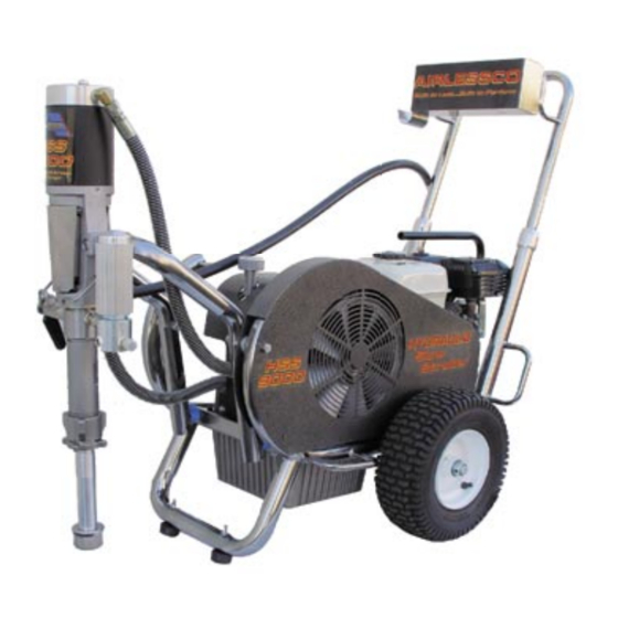
- Page 1 ERVICE PERATION ANUAL HSS 9000 Hydraulic Airless Paint Sprayer Form No. 001-771 JUN07...
-
Page 2: Table Of Contents
HYDRAULIC INLET AND MOTOR ASSEMBLIES ..........25 FRAME ASSEMBLY .................... 26 DIRECT IMMERSION ASSEMBLY ..............27 SIPHON UNIT ASSEMBLY ................. 28 MOTOR/ENGINE W/CARRY PLATE ASSEMBLY ..........29 AIRLESSCO by Durotech Co. 5397 N. Commerce Ave., Moorpark, CA 93021 Tel: 805-523-0211 FAX: 805-523-1063 Internet: www.airlessco.com Email: techsupport@airlessco.com... -
Page 3: Introduction
2, 3 & 4. READ, LEARN, and FOLLOW the Pressure Relief Pro ce dure on Page 11 of this manual. All Service Procedures to be performed by an Authorized Airlessco Service Center ONLY. NO MODIFICATIONS or alterations of any AIRLESSCO Equipment or part is allowed. -
Page 4: Safety Warnings
SAFETY WARNINGS HIGH PRESSURE SPRAY CAN CAUSE EXTREMELY SERIOUS INJURY. Handle as you would a loaded firearm. Follow the PRESSURE RELIEF PROCEDURE DO NOT USE HALOGENATED SOLVENTS IN THIS SYSTEM. The prime valve, and most airless guns have aluminum parts and may explode. Cleaning agents, coatings, paints or adhesives may contain halogenated hydrocarbon solvents. - Page 5 SAFETY WARNINGS ALWAYS INSPECT SPRAYING AREA HOSES • Tighten all of the fluid connections securely before each • Keep the spraying area free from obstructions. use. High pressure fluid can dislodge a loose coupling or • Make sure the spraying area has good ventilation allow high pressure spray to be emitted from the coupling to safely remove vapors and mists.
- Page 6 SAFETY WARNINGS • ALWAYS use approved high pressure fittings and Always Follow Recommended Pressure replacement parts. and Operating Instructions • ALWAYS ensure fire extinquishing equipment is readily available and properly maintained. KEEP CLEAR OF MOVING PARTS Keep clear of moving parts when starting or operating the PREVENT STATIC SPARKING FIRE/EXPLOSIONS sprayer.
-
Page 7: Gas Engine Precautions
GAS ENGINE PRECAUTIONS Gasoline & its vapors are extremely flammable & explosive.Fire or explosion can cause severe burns or death. WHEN ADDING FUEL • Turn engine OFF and let engine cool at least 2 minutes before removing gas cap. • Fill fuel tank outdoors or in well ventilated area. •... - Page 8 GAS ENGINE PRECAUTIONS (continued) • If fuel spills, wait until it evaporates before starting engine. • If engine floods, set choke to OPEN/RUN position, place throttle in FAST and crank until engine starts. WHEN OPERATING EQUIPMENT • Do not tip engine or equipment at angle which causes gasoline to spill.
-
Page 9: Flushing
FLUSHING 1. New Sprayer 5. Storage Your sprayer was factory tested in an oil solution which Always relieve pressure (See pressure relief was left in the pump. Before using oil-base paint, flush procedure on page 11) prior to storage or when with mineral spirits only. -
Page 10: How To Flush
HOW TO FLUSH 1. Be sure the gun safety latch is engaged and there 6. Disengage the gun safety latch and squeeze the is no spray tip in the gun. Refer to page 14 on how gun trigger. Turn Pressure Control Knob (Figure 4) to lock the safety latch and the gun's safety features. -
Page 11: Setting Up
Use thread seal on tapered male threads only. 3. Flush the sprayer 2. Fill the packing nut/wet cup with 5 drops of Airlessco Throat Seal As per "How To Flush" in this manual (Page 8). Oil (TSO). See (Figure 5). - Page 12 Check the spray pattern. The tip size and angle determines the pattern width and flow rate. WARNING Be sure to relieve pressure in the pump after filling with Airlessco Pump Conditioner. WARNING 5. When Shutting off the Sprayer Follow the "Pressure Relief Procedure".
-
Page 13: Pressure Relief Procedure
Step 4. If you suspect that pressure hasn't been relieved due to damaged Prime Valve or other reason, engage the gun safety latch and take your unit to an authorized Airlessco Service Center. -
Page 14: Spray Gun Operation
SPRAY GUN OPERATION SPRAY GUN Attach spray gun to airless unit and tighten fittings securely. Set the gun safety latch. (Also may be called gun safety lock, FIGURE 7 or trigger lock) * The gun safety latch should always be set when the gun is not being triggered. -
Page 15: Sraying Troubleshooting Chart
SPRAYING TROUBLESHOOTING CHART Problem Cause Correction Coarse Spray, Spotty Pattern Pressure setting low Increase pressure setting Irratic spray gun/hand motion Use a steady, parallel pass Excessive Overspray (Fogging) Pressure setting high Reduce pressure setting Paint over thinned/reduced/cut Use less thinner/water/reducer Spray Pattern Excessively Wide Incorrect fan width selection Select narrower fan width tip*... -
Page 16: Rev-Tip™ Selection Chart
REV-TIP SELECTION CHART ™ Spray tip selection is based on paint viscosity, paint type, Spray tip size is based on how many gallons of paint per and job needs. For light viscosities (thin paints), use a minute can be sprayed through the tip. Do not use a tip smaller tip;... -
Page 17: Field Troubleshooting
FIELD TROUBLESHOOTING PROBLEM CAUSE SOLUTION Unit doesn't prime †Airleak due to: • Loose Suction Nut • Tighten Suction Nut • Worn O-Rings • Service Suction Assy • Leak in Siphon Assy • Replace Siphon Assy †Stuck or Fouled Balls †Service outlet valve suction assembly Unit primes but has no †Pressure set too low... -
Page 18: Servicing The Fluid Pump
SERVICING THE FLUID PUMP Disassembly of the Fluid Pump - Figure 19 Fluid Pump Removal Refer to Figure 12 1. Remove Fluid Pump from machine - Refer to Fluid 1. Follow the Pressure Relief Procedure page 11. Pump Removal, Page 16. 2. -
Page 19: Servicing Outlet Valve Assembly
SERVICING THE FLUID PUMP Fluid Pump Reinstallation - Refer to Figure 12 1. With the Retaining Ring loosly in place around the pump piston, thread the Fluid Pump in to the Yoke (186-078) until the top edge of the Outlet Housing (187-086) is one thread above the inside edge of the Yoke threaded bore. -
Page 20: Servicing Inlet Valve Assy, Inlet Suction Assemblies
SERVICING INLET VALVE ASSEMBLY Disassembly of Inlet Valve - Figure 14 1. Relieve pressure following Pressure Relief steps on FIGURE 14 page 11. 2. Remove Inlet Valve Housing (187-084). 3. Remove Ball Guide (187-087), O-Rings and Inlet Ball (187-092). Remove Inlet Seat (187-086). 7. -
Page 21: Optional Suction Assemblies
OPTIONAL SUCTION ASSEMBLIES FIGURE 17 5 Gal. Latex Suction Assembly 119-108 FIGURE 17 PARTS LIST 141-008 ITEM # PART # DESCRIPTION 301-514 250-116 100-668 Suction Elbow 100-664 189-587 Suction Nut 189-587 100-664 1" ID Suction Hose 100-668 250-116 Clamp ITEM NO. PART NUMBER 301-514 5 Gal Suction Tube... -
Page 22: Packing Replacement Procedures
PACKING REPLACEMENT PROCEDURES REASSEMBLY - Figure 19 REASSEMBLY - Figure 19 1. Intall PTFE O-Ring (106-004) and Extension Tube 1. Soak all Leather Packings (187-074) in oil for 5-10 minutes (187-102) into bottom of Outlet Housing and tighten until the before assembly. -
Page 23: Paint Pump Assembly
PAINT PUMP ASSEMBLY FIGURE 19 *See Page 19 For Optional Suction Assemblies... -
Page 24: Manifold Filter
MANIFOLD FILTER - PN 119-084 FIGURE 20 FIGURE 20 PARTS LIST ITEM # PART # DESCRIPTION ITEM # PART # DESCRIPTION 111-202 Housing Bowl 100-028 1/4 NPT-M Plug 301-256 Spring 100-129 3/8 NPT-M Plug 111-204 60 Mesh Filter 169-010 3/8 NPT-M X 3/8 NPT-M Nipple 100-005 3/8 NPS-F X 3/8 NPT-M Swivel 106-007... -
Page 25: Prime Valve Assembly
PRIME VALVE ASSEMBLY - 119-083 FIGURE 21 115-068 117-046 115-063 115-072 115-303 115-071 115-064 115-065 115-067 115-074 115-012 115-069 115-029 115-073 ITEM NO. PART NUMBER THIS DOCUMENT CONTAINS INFORMATIO PROPRIETARY TO DUROTECH CO. IT SHAL NOT BE REPRODUCED, USED OR DISCLOS TO ANYONE WITHOUT THE PRIOR WRITT PREMISSION OF DUROTECH CO. -
Page 26: Hydraulic Pump And Reservoir
HYDRAULIC PUMP AND RESERVOIR FIGURE 22 Note: Hydraulic Reservoir and Hydraulic System requires 3.5 Gallons of Pennzoil A.W. Hydraulic Oil #46 The minimum Oil Level must be approximately halfway up the Filler Tube, Never below. FIGURE 22 PARTS LIST ITEM # PART # DESCRIPTION ITEM #... -
Page 27: Hydraulic Inlet And Motor Assemblies
HYDRAULIC INLET ASSEMBLY FIGURE 23 FIGURE 23 PARTS LIST ITEM # PART # DESCRIPTION ITEM # PART # DESCRIPTION 189-570 Hydraulic Pump 189-523 Threaded Nipple 189-562 O-Ring, Pump 189-565 Strainer, Suction 189-561 Pump Inlet Fitting 189-568 Inlet Connector HYDRAULIC MOTOR ASSEMBLY FIGURE 24 FIGURE 24 PARTS LIST ITEM #... -
Page 28: Frame Assembly
FRAME ASSEMBLY FIGURE 25 FIGURE 25 PARTS LIST ITEM # PART # DESCRIPTION ITEM # PART # DESCRIPTION 189-599 Frame, Bare 113-030 Spacer FIGURE XX PARTS LIST 189-576 Pivot Tube 143-029 Set Collar 301-165 Wheel 119-081 Hex Bolt 189-558 Bumper, Stop 140-029 Washer 119-077... -
Page 29: Direct Immersion Assembly
DIRECT IMMERSION ASSEMBLY FIGURE 26 FIGURE 26 PARTS LIST ITEM # PART # DESCRIPTION ITEM # PART # DESCRIPTION 189-554 Frame Assembly 111-014 Pressure Gauge 189-571 Hydraulic Assy 119-083 Prime Valve 189-580 Pump Shroud 119-084 Filter Manifold 189-606 Paint Pump Assy 188-125 Screw 189-548... -
Page 30: Siphon Unit Assembly
SIPHON UNIT ASSEMBLY FIGURE 27 FIGURE 27 PARTS LIST ITEM # PART # DESCRIPTION ITEM # PART # DESCRIPTION 189-554 90 deg Elbow Frame Assy 100-004 189-571 90 deg Elbow 100-133 Hydraulic Assembly Paint Pump Assy 140-035 Flat Washer 189-608 100-307 Pressure Control Screw... -
Page 31: Motor/Engine W/Carry Plate Assembly
MOTOR/ENGINE W/CARRY PLATE ASSEMBLY FIGURE 28 175-025 189-627 FIGURE 28 PARTS LIST ITEM NO. PART NUMBER ITEM # PART # DESCRIPTION THIS DOCUMENT CONTAINS INFORMATION 189-593 Lifting Handle/Plate Assembly PROPRIETARY TO DUROTECH CO. IT SHALL 189-531 Pulley, Gas Engine NOT BE REPRODUCED, USED OR DISCLOSED 189-526 Pulley, Electric Motor (Not Shown) TO ANYONE WITHOUT THE PRIOR WRITTEN...