Table of Contents
Advertisement
Operation/Repair/Parts
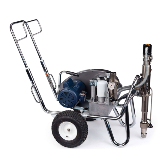
HSS9950 Hydraulic Sprayers
For professional use only.
Not approved for use in European explosive atmosphere locations.
For the application of architectural paints and coatings.
3300 psi (22.7 MPa, 227 bar) Maximum Working Pressure
Important Safety Instructions
Read all warnings and instructions in this manual and in related manuals.
Be familiar with the controls and the proper usage of the equipment.
Save these instructions.
Related Manuals:
3A0413
Gun
334654
Pump
310812
Electric Motor
3A4102C
EN
ti29199a
Advertisement
Table of Contents

Related Manuals for AIRLESSCO HSS9950


Summary of Contents for AIRLESSCO HSS9950
- Page 1 Operation/Repair/Parts 3A4102C HSS9950 Hydraulic Sprayers For professional use only. Not approved for use in European explosive atmosphere locations. For the application of architectural paints and coatings. 3300 psi (22.7 MPa, 227 bar) Maximum Working Pressure Important Safety Instructions Read all warnings and instructions in this manual and in related manuals.
-
Page 2: Table Of Contents
HSS9950 Frame and Belt Guard Parts ....30 HSS9950 Electric Motor Parts ......32 HSS9950 Gasoline Engine Parts . -
Page 3: Warnings
Warnings Warnings The following warnings are for the setup, use, grounding, maintenance, and repair of this equipment. The exclamation point symbol alerts you to a general warning and the hazard symbols refer to procedure-specific risks. When these symbols appear in the body of this manual or on warning labels, refer back to these Warnings. - Page 4 All parts of the spray system, including the pump, hose assembly, spray gun, and objects in and around the spray area shall be properly grounded to protect against static discharge and sparks. Use Airlessco conductive or grounded high-pressure airless paint sprayer hoses.
-
Page 5: Internal Combustion Engine Warnings
Warnings Internal Combustion Engine Warnings FIRE AND EXPLOSION HAZARD Flammable fumes, such as solvent and paint fumes, in work area can ignite or explode. To help prevent fire and explosion: • Use equipment only in well ventilated area. • Do not fill fuel tank while engine is running or hot; shut off engine and let it cool. Fuel is flammable and can ignite or explode if spilled on hot surface. -
Page 6: Electric Motor/Internal Combustion Engine Warnings
• This system is capable of producing 3300 psi (22.8 MPa, 228 bar). Use Airlessco replacement parts or accessories that are rated a minimum of 3300 psi (22.8 MPa, 228 bar). • Always engage the trigger lock when not spraying. Verify the trigger lock is functioning properly. - Page 7 Do not kink or over-bend the hose. • Do not expose the hose to temperatures or to pressures in excess of those specified by Airlessco. • Do not use the hose as a strength member to pull or lift the equipment.
- Page 8 Warnings ENTANGLEMENT HAZARD Rotating parts can cause serious injury. • Keep clear of moving parts. • Do not operate equipment with protective guards or covers removed. • Do not wear loose clothing, jewelry or long hair while operating equipment. • Equipment can start without warning.
-
Page 9: Component Identification
Component Identification Component Identification bar/MPa ti29200a Gun Trigger Lock Pressure Gauge Grounding Clamp Pressure Control Serial Number Tag Hydraulic Pump Valve Prime/Drain Valve Threaded Pump Connection Hydraulic Oil Cap / Dipstick Displacement Pump Hydraulic Oil Filter Inlet Strainer Paint Filter Engine On/Off Switch Engine Controls Electric Motor On/Off Switch... -
Page 10: Grounding
Grounding Grounding Grounding Procedure for Grounding Procedure for Gas Engine Electric Motor ELECTRIC SHOCK HAZARD The equipment must be grounded to Improper grounding can cause electric reduce the risk of static sparking. Static shock. sparking can cause fumes to ignite or •... - Page 11 Grounding Grounding of Pails Always ground a metal pail: connect a ground wire to the pail. Clamp one end to the Solvent pails used when flushing: Follow pail and the other end to a true earth ground local code. Use only conductive metal pails, such as a water pipe.
-
Page 12: Setup
Setup Setup Lift belt guard. Remove belt. Tilt engine/motor and remove engine/motor. Change Engine or Motor ti18192a Turn motor OFF and unplug or turn Tilt engine/motor. Install engine/motor. engine to the OFF/STOP position. Install belt. Lower belt guard. Loosen belt guard knob and motor clamp. - Page 13 Setup Complete Setup Remove Tip Guard. Screw inlet strainer to bottom of suction Connect appropriate high-pressure hose and hand tighten securely. hose to sprayer. ti18418b Install hose to spray gun and tighten When spraying texture, remove inlet securely. strainer and filter bowl screen. ti8692a ti29202a ti18418a...
- Page 14 Setup Fill throat packing nut with packing seal 10. Check hydraulic oil level. Add only fluid to prevent premature packing wear. Hydraulic Oil, ISO Grade 46, 169236 (5 Do this each time you spray. gallon/18.9 liter) or 207428 (1 gallon/3.8 liter).
-
Page 15: Pressure Relief Procedure
Pressure Relief Procedure Pressure Relief Procedure Follow the Pressure Relief Move pump valve to OFF and turn pressure control knob fully counter- Procedure whenever you see this clockwise to lowest setting. symbol. Disengage trigger lock. Hold metal part of gun firmly to side of grounded metal pail, and trigger gun to relieve pressure. -
Page 16: Startup (Internal Combustion Models)
Startup (Internal Combustion Models) Startup (Internal Combustion Models) Set hydraulic pump valve OFF. Place displacement pump in grounded metal pail partially filled with flushing fluid. Attach ground wire to pail and to earth ground. ti9686a Start gasoline engine: Move fuel valve to open. ti29205a Turn prime valve down to DRAIN ti29206b... - Page 17 Startup (Internal Combustion Models) Set hydraulic pump valve ON (hydraulic motor is now active). ti5263a After engine starts, move choke to open. ti9687a Increase pressure enough to start hydraulic motor stroking and allow fluid to circulate for 15 seconds; turn pressure down, turn prime valve horizontal.
- Page 18 Startup (Internal Combustion Models) Hold gun against grounded metal 10. Place siphon tube in paint pail. flushing pail. Trigger gun and increase fluid pressure slowly until pump runs smoothly. Release trigger and allow sprayer to build pressure. Engage trigger lock. High-pressure spray is able to inject toxins into the body and cause serious bodily ti9695a...
-
Page 19: Startup (Electric Models)
Startup (Electric Models) Startup (Electric Models) Set hydraulic pump valve OFF. Place displacement pump in grounded metal pail partially filled with flushing fluid. Attach ground wire to pail and to earth ground. ti9686a Plug cord into outlet. Turn motor ON. ti29205a Turn prime valve down. - Page 20 Startup (Electric Models) Increase pressure enough to start hydraulic motor stroking and allow fluid to circulate for 15 seconds; turn pressure down, turn prime valve horizontal. High-pressure spray is able to inject toxins into the body and cause serious bodily injury.
-
Page 21: How To Spray
How to Spray How to Spray Tip and Guard Assembly Spray Spray test pattern. Increase pressure to eliminate heavy edges. Use smaller tip size if pressure adjustment can not eliminate heavy edges. Perform Pressure Relief Procedure, page 15. Engage gun trigger lock. Insert seat and seal using end of finger hold. -
Page 22: Clear Tip Clogs
How to Spray Clear Tip Clogs Engage trigger lock. Return tip to original position. Disengage trigger lock and continue spraying. Release trigger, engage trigger lock. Rotate tip. Disengage trigger lock. Trigger gun to clear clog. ti29221a ti29220a 3A4102C... -
Page 23: Clean Up
Clean Up Clean Up Turn motor switch ON or turn engine ON and start engine. Turn hydraulic pump valve ON. Turn prime valve forward to SPRAY position. Perform Pressure Relief Procedure, page 15. Remove Guard and tip. ti29222a ti25223a Remove displacement pump from paint Hold gun against pail. - Page 24 Clean Up Move gun to waste pail, hold gun against Engage trigger lock. Remove filters from pail, trigger gun to thoroughly flush gun and sprayer, if installed. Clean and system. Release trigger and engage inspect. Reinstall filters. trigger lock. ti8692a 10.
-
Page 25: Maintenance
Maintenance Maintenance WEEKLY: Remove engine air filter cover and clean element. Replace element, if necessary. If operating in an unusually dusty environment: check filter daily and replace, if necessary. Replacement elements can be purchased from your local Briggs & Stratton Vanguard dealer. -
Page 26: Troubleshooting
Troubleshooting Troubleshooting Problem Cause Solution Internal combustion engine Hydraulic pressure is too high Turn hydraulic pressure knob pulls hard (won’t start) counterclockwise to lowest setting Gasoline engine does not start Switch OFF, low oil, no gasoline Consult engine manual Fuel shut off valve closed Open fuel shut off valve Gasoline engine does not work Faulty engine... - Page 27 Troubleshooting Problem Cause Solution Excessive leakage around Piston rod seal worn or Replace parts. See pump hydraulic motor piston rod wiper damaged manual. Fluid delivery is low Pressure setting too low Increase pressure Displacement pump outlet filter Clean or replace. (if used) is dirty or clogged Hydraulic motor is worn or Bring sprayer to distributor for...
-
Page 28: Standard Series Pump
Standard Series Pump Standard Series Pump Removal Push retaining ring up; push out pin. See pump manual 334654 for pump repair. Flush pump. Perform Pressure Relief Procedure, page 15. Remove strainer and paint hose. Loosen jam nut. Unscrew pump. ti29225a 3A4102C... -
Page 29: Installation
Standard Series Pump Installation NOTICE If pin is loose, parts could break off and If pump jam nut loosens during operation, project through the air, resulting in serious the threads of the bearing housing and injury or property damage. Make sure pin is drive train will be damaged. -
Page 30: Hss9950 Frame And Belt Guard Parts
HSS9950 Frame and Belt Guard Parts HSS9950 Frame and Belt Guard Parts Ref. Torque Ref. Torque Inflate tires to 25-35 psi 120-130 in-lb (13.6 - 14.7 N•m) (1.7-2.4 bar) ti25332a 3A4102C... - Page 31 HSS9950 Frame and Belt Guard Parts HSS9950 Frame and Belt Guard Parts List Ref. Part Description Qty. 101354 PIN, spring, straight 260212 SCREW, hex washer hd, thd form 112827 BUTTON, snap 119509 WHEEL, pneumatic 867539 SCREW, cap, hex hd 100527...
-
Page 32: Hss9950 Electric Motor Parts
HSS9950 Electric Motor Parts HSS9950 Electric Motor Parts Ref. Torque Ref. Torque 25-30 in-lb (2.9 - 3.4 N•m) Apply Loctite 242 215-235 in-lb (24.3 - 26.6 N•m) 58-62 in-lb (6.6 - 7.0 N•m) 119a ti25479a Ref. Part Description Qty. Ref. -
Page 33: Hss9950 Gasoline Engine Parts
HSS9950 Gasoline Engine Parts HSS9950 Gasoline Engine Parts Ref. Torque Ref. Torque 120-130 in-lb (13.6 - 14.7 N•m) Apply Loctite 242 58-62 in-lb (6.6 - 7.0 N•m) ti29231a Ref. Part Description Qty. Ref. Part Description Qty. 15B314 SLEEVE, motor shaft... -
Page 34: Hss9950 Reservoir & Filter Parts
HSS9950 Reservoir & Filter Parts HSS9950 Reservoir & Filter Parts Ref. Torque Ref. Torque 58-62 in-lb (6.6 - 7.0 N•m) 15-25 in-lb (1.7 - 2.8 N•m) Apply Loctite 242 Apply Loctite 277 90-110 in-lb (10.2 - 12.4 N•m) 110-120 in-lb (12.4 - 13.6 N•m) 355-395 in-lb (40.1 - 44.6 N•m) - Page 35 HSS9950 Reservoir & Filter Parts HSS9950 Reservoir & Filter Parts List Ref. Part Description Qty. Ref. Part Description Qty. 15B438 KNOB, pressure 15E476 BRACKET, retainer, 117560 SCREW, set, socket head motor 246167 TUBE, hydraulic, case 116914 BELT, V, AX42 (electric)
-
Page 36: Hydraulic Motor & Displacement Pump Parts
Hydraulic Motor & Displacement Pump Parts Hydraulic Motor & Displacement Pump Parts Ref. Torque Ref. Torque 145-155 ft-lb (196.6 - 210.2 N•m) 140-160 in-lb (15.8 - 18.1 N•m) 12-18 ft-lb (16.3 - 24.4 N•m) 70-80 ft-lb (94.9 - 108.5 N•m) 290a 290c 290b... - Page 37 Hydraulic Motor & Displacement Pump Parts Hydraulic Motor & Displacement Pump Parts List Ref. Part Description Qty. Ref. Part Description Qty. 281+ 178207 BEARING, piston 101566 NUT, lock 288 248991 SLEEVE, hydraulic 189920 STRAINER, (1-11 1/2 289 15A726 NUT, jam npsm) 290...
-
Page 38: Hss9950 Spray Gun & Hose Parts
HSS9950 Spray Gun & Hose Parts HSS9950 Spray Gun & Hose Parts 202c 202b 202a 202f 202e 202d ti29355a Ref. Part No. Description Ref. Part No. Description 202d 159841 ADAPTER, 3/8 x 1/4 in. npt 202a HSE3850 HOSE, grounded, nylon, 159239 ADAPTER, 1/2 x 3/8 in. -
Page 39: Technical Data
Technical Data Technical Data HSS9950 Electric Metric Maximum fluid working pressure 3300 psi 22.7 MPa, 227 bar Hydraulic reservoir capacity 1.25 gallons 4.75 liters Motor 2.2 kW 3.0 HP Voltage, Amperage Frequency Phase 220 VAC, 15.0 A 220 VAC, 15.0 A,... - Page 40 Technical Data HSS9950 Gas Metric Maximum fluid working pressure 3300 psi 22.7 MPa, 227 bar Hydraulic reservoir capacity 1.25 gallons 4.75 liters Maximum hydraulic pressure 1855 psi 12.8 MPa,128 bar Engine - Vanguard 205 cc (6.5 HP @ 3900 RPM) 205 cc (4.8 KW @ 3900 RPM)
- Page 41 Notes Notes 3A4102C...
- Page 42 Notes Notes 3A4102C...
-
Page 43: Airlessco Standard Warranty
With the exception of any special, extended, or limited warranty published by Airlessco, Airlessco will, for a period of twelve months from the date of sale, repair or replace any part of the equipment determined by Airlessco to be defective. This warranty applies only when the equipment is installed, operated and maintained in accordance with Airlessco’s written recommendations. - Page 44 All written and visual data contained in this document reflects the latest product information available at the time of publication. Airlessco reserves the right to make changes at any time without notice. Original Instructions. This manual contains English. MM 3A4102 GRACO INC.