AIRLESSCO HSS 9000 Manual
Hide thumbs
Also See for HSS 9000:
- Service & operation manual (32 pages) ,
- Operating & parts manual (33 pages)

Related Manuals for AIRLESSCO HSS 9000


Summary of Contents for AIRLESSCO HSS 9000
- Page 1 AIRLESS PAINT SPRAYER SERVICE/OPERATION MANUAL AIRLESSCO HSS 9000 / HSS 11000 001-771 DEC 08...
-
Page 2: Table Of Contents
Power Unit ............... 24 24. Suction Assembly............25 Suction Assemblies ............25 25. Suction Assembly............25 Airlessco Accessories ............. 26 26. Inlet Suction Assembly ..........25 27. Inlet Suction Assembly ..........25 Airlessco 5397 N. Commerce Ave, Moorpark, CA 93021... -
Page 3: Introduction
NOTE - Identifies essential procedures or extra information. All Service Procedures to be performed by an Authorized Airlessco Service Center ONLY. NO MODIFICATIONS or alterations of any AIRLESSCO Equipment or part is allowed. -
Page 4: Warnings
WARNINGS NOTE TO PHYSICIAN: Injection in the skin is a traumatic MEDICAL ALERT - Airless Spray Wounds injury. It is important to treat the injury surgically as soon as If any fluid appears to penetrate your skin, get EMERGENCY possible. DO NOT DELAY treatment to research toxicity. Tox- MEDICAL CARE AT ONCE. - Page 5 WARNINGS - CONTINUED HOSES GROUNDING Tighten all fluid connections securely before each use. High Ground the sprayer and other components in the system pressure fluid can dislodge a loose coupling or allow high to reduce the risk of static sparking, fire or explosion which pressure spray to be emitted from the coupling and result in can result in serious bodily injury and property damage.
- Page 6 WARNINGS - CONTINUED AVOID COMPONENT RUPTURE FLUSHING Reduce the risk of injection injury, static sparking or This sprayer operates at 3300 psi (225 bar). ALWAYS be splashing by following the specific cleaning procedure on sure that all components and accessories have a maximum page 7 and 9.
-
Page 7: Setting Up
- c below being sure not Fill the Packing Nut/Wet to spill any fuel. Cup with 5 drops of Airlessco Throat Seal a. Close the fuel shutoff valve. Oil (TSO). b. Use only clean, fresh, well-known brands of unleaded regular grade gasoline. -
Page 8: How To Flush
HOW TO FLUSH FIG. 2 FLUSHING PROCEDURE PRIME VALVE 1. Be sure the gun safety latch is engaged and there is no spray tip in the gun. Refer to Fig. 2. Refer to your CLOSED separate instruction manual provided with your gun on (Pressure) its safety features and how to engage safety latch. -
Page 9: Starting Up
STARTING UP 1. LEARN THE CONTROLS WARNING If you spray into the paint bucket, always use the lowest spray PRESSURE CONTROL KNOB - used to adjust pressure and maintain firm metal to metal contact between pressure only. Turn clockwise to increase pressure and gun and container. - Page 10 STARTING UP CONTINUED 6. CLEANING A CLOGGED TIP 7. WHEN SHUTTING OFF SPRAYER a. Whenever you stop spraying, even for a short break, a. Follow PRESSURE RELIEF PROCEDURE on page 9. follow the "PRESSURE RELIEF PROCEDURE ". b. Clean the front of the tip frequently (with toothbrush only) b.
-
Page 11: Pressure Relief Procedure
If you suspect that pressure hasn't been relieved due to damaged Prime/Pressure Relief Valve or other reason, engage the gun safety latch and take your unit to an authorized Airlessco Service Center. WARNING NEVER leave pump unattended while under pressure! -
Page 12: Airless Spray Gun Operation
SPRAY FIG. 7 Attach spray gun to airless unit and tighten fittings securely. GUN SAFETY LATCH GUN SAFETY IN LOCKED POSITION LATCH Set the gun safety latch. (Also may be called gun safety lock, or trigger lock) * The gun safety latch should always be set when the gun is not being triggered. -
Page 13: Airless Spray Gun Troubleshooting
AIRLESS SPRAY TROUBLESHOOTING DEFECTS CAUSE CORRECTION Coarse spray Low pressure Increase the pressure Excessive fogging High pressure Reduce the pressure to satisfactory pattern distrabution (overspray) Material too thin Use less thinner Patten too wide Spray angle too large Use smaller spray angle tip Pattern too narrow Spray angle too small Use larger spray angle tip (if coverage is OK, try tip in same... -
Page 14: Line Striping Tip Chart
TIP SELECTION GUIDE Spray tip selection is based on paint viscosity, paint type, & be sprayed through the tip. Do not use a tip larger than job needs. For light viscosities (thin paints), use a smaller maximum pump flow rate or capacity the sprayer can tip;... -
Page 15: Field Troubleshooting
FIELD TROUBLESHOOTING PROBLEM CAUSE SOLUTION There is spitting from the gun. The fluid supply is low or empty • Refill the supply container. Air entrapped in the fluid pump or hose • Check for loose connections ont he siphon assembly, tighten, then reprime pump. Paint leaks into the wet cup The packing nut/wet cup is loose. -
Page 16: Servicing The Fluid Pump
SERVICING THE FLUID PUMP FLUID PUMP REMOVAL DISASSEMBLY OF THE FLUID PUMP REFER TO FIGURE 11 REFER TO FIGURE 14 1. Follow the PRESSURE RELIEF PROCEDURE page 9. 1. Remove Fluid Pump from machine. 2. Flush the material you are spraying out of the machine. 2. -
Page 17: Servicing The Outlet Valve Assembly
SERVICING OUTLET VALVE ASSEMBLY FIG. 12 DISASSEMBLY OF THE OUTLET VALVE REFER TO FIGURE 12 1. Remove Fluid Pump from machine - Refer to Fluid Pump Removal, Page 14. 2. Remove Outlet Valve Assembly - Follow steps 1-9, Disassembly of the Fluid Pump, Page 14. 3. -
Page 18: Packing Replacement Procedures
PACKING REPLACEMENT PROCEDURES DISASSEMBLY REASSEMBLY REFER TO FIGURE 14 REFER TO FIGURE 14 1. Intall PTFE O-Ring and Extension Tube into bottom 1. Soak all Leather Packings in oil for 5-10 minutes before of Outlet Housing and tighten until the Extension Tube assembly. -
Page 19: Fluid Pump Assembly
FLUID PUMP ASSEMBLY FIG. 14... -
Page 20: Manifold Filter
MANIFOLD FILTER (119-084) FIG. 15 PARTS LIST FIGURE 15 Item No. Part No. Description 111-202 Housing Bowl 301-356 Spring 111-204 60 Mesh Filter 100-005 Swivel 100-003 Swivel 111-201 Housing Base 100-028 Plug 100-129 Plug 169-010 Nipple 106-007 O-Ring, PTFE 111-203 Filter Support PRIME VALVE (119-083) FIG. -
Page 21: Hydraulic Pump And Reservoir
HYDRAULIC PUMP AND RESERVOIR (189-571) FIG. 17 2, 3 27, 28 23, 24 19, 20 11, 12, 13, HYDRAULIC INLET 14, 15 ASSEMBLY NOTE: Hydraulic Reservoir and Hydraulic System requires 3.5 gallons of Pennzoil A.W. Hydraulic Oil #46. The minimum Oil Level must be approximately halfway up the Filler Tube. -
Page 22: Hydraulic Motor Assembly
HYDRAULIC MOTOR ASSEMBLY FIG. 18 1, 2 1, 6 PARTS LIST FIGURE 18 PARTS LIST FIGURE 18 CONT Item No. Part No. Description Item No. Part No. Description 100-133 Elbow (2) 119-099 Front Cover 189-545 High Pressure Hose 186-078 Yoke 186-100 Hydraulic Motor 189-546... -
Page 23: Frame Assembly
FRAME ASSEMBLY FIG. 19 1, 2, 3, 4 8, 9, 10, 11, 12 21, 22, 16, 14, 15, 16, 17 14, 15 PARTS LIST FIGURE 19 PARTS LIST FIGURE 19 CONT Item No. Part No. Description Item No. Part No. Description 140-029 Washer... -
Page 24: Direct Immersion Unit
DIRECT IMMERSION ASSEMBLY FIG. 20 17, 18 4, 18 7, 8, 9 10, 11 14, 12, 16 12, 13, 14 PARTS LIST FIGURE 20 PARTS LIST FIGURE 20 CONT Item No. Part No. Description Item No. Part No. Description 189-554 Frame Assy 188-125 Screw... -
Page 25: Siphon Unit
SIPHON UNIT ASSEMBLY FIG. 21 15, 16 3, 16 6, 7, 8 9, 10 11, 13, 14 11, 12, 13 20, 21, 22, 23 27, 28 PARTS LIST FIGURE 21 PARTS LIST FIGURE 21 CONT Item No. Part No. Description Item No. -
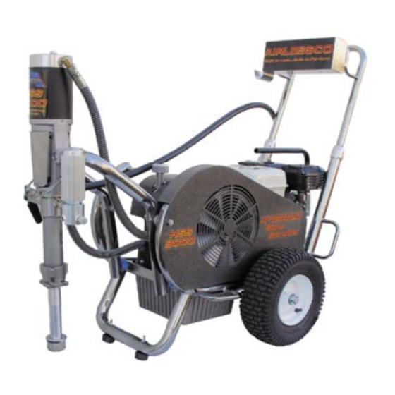
Page 26: Power Unit
POWER UNIT - HSS 9000 FIG. 22 PARTS LIST FIGURE 22 Item No. Part No. Description 175-025 GX200 Honda Gas Engine 175-034 6.5HP Durotech Gas Engine 100-361 Set Screw 189-531 Pully 136-123 Screw 113-022 113-023 Lock Washer 189-593 Lifting Handle/Plate Assy... -
Page 27: Suction Assemblies
OPTIONAL SUCTION ASSEMBLIES FIG. 24 FIG. 25 PARTS LIST FIGURE 24 PARTS LIST FIGURE 25 Item No. Part No. Description Item No. Part No. Description 189-587 Suction Nut 119-107 Swivel Assy 100-668 Suction Elbow 100-664 1” ID Suction Hose 100-664 1”... -
Page 28: Airlessco Accessories
188-187 6 oz. Bottle kept in smaller than 5 gallon containers. 188-392 1 qt. Bottle Threads onto pick-up tube of carry or LoBoy framed Airlessco sprayers. 331-775 6 Liter Paint Hopper XTEND-A-POLE SYSTEM PUMP CONDITIONER Standard Tip Extension Should be used on piston pumps between uses to prevent paint from drying on the piston &...