Table of Contents
Advertisement
EMPIRE
EMPIRE
Comfort Systems
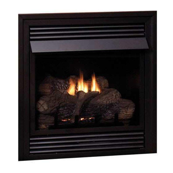
Vent-Free Gas Fireplaces
This appliance may be installed in an aftermarket,
permanently located, manufactured (mobile) home,
where not prohibited by local codes.
This appliance is only for use with the type of gas in-
dicated on the rating plate. This appliance is not con-
vertible for use with other gases.
If the information in these instructions are not fol-
lowed exactly, a fire or explosion may result caus-
ing property damage, personal injury or loss of life.
— Do not store or use gasoline or other flammable
vapors and liquids in the vicinity of this or any
other appliance.
— WHAT TO DO IF YOU SMELL GAS
•
Do not try to light any appliance.
•
Do not touch any electrical switch; do not use
any phone in your building.
•
Immediately call your gas supplier from a
neighbor's phone. Follow the gas supplier's
instructions.
•
If you cannot reach your gas supplier, call the
fire department.
— Installation and service must be performed by a
qualified installer, service agency or the gas sup-
plier.
INSTALLATION INSTRUCTIONS
WARNING
AND
OWNER'S MANUAL
GAS FIREpLACE
VFD26FM(2,3)0(N,W,C)(N,p)-2
VFD26Fp(2,3)0L(N,p)-2
VFD26Fp30L10(N,p)-3
VFD26Fp70L10(N,p)-1
Installer:
Consumer: Retain this manual for future reference.
This is an unvented gas-fired heater. It uses air (oxy-
gen) from the room in which it is installed. provisions
for adequate combustion and ventilation air must be
provided. Refer to pages 9 and 10.
WATER VApOR: A BY-pRODUCT OF UNVENTED
ROOM HEATERS
Water vapor is a by-product of gas combustion. An
unvented room heater produces approximately one
ounce (30ml) of water for every 1,000 BTU's (.3KW's)
of gas input per hour. Refer to page 8.
If not installed, operated and maintained in accor-
dance with the manufacturer's instructions, this
product could expose you to substances in fuel or
from fuel combustion which can cause death or seri-
ous illness.
UNVENTED
MODELS
VFD26Fp70L(N,p)-1
Leave this manual with the appliance.
WARNING
Page 1
Advertisement
Table of Contents
Troubleshooting

Related Manuals for Empire Comfort Systems VFD26FM(2,3)0(N,W,C)(N,P)-2VFD26FM20NN-2


Summary of Contents for Empire Comfort Systems VFD26FM(2,3)0(N,W,C)(N,P)-2VFD26FM20NN-2
- Page 1 INSTALLATION INSTRUCTIONS EMPIRE EMPIRE OWNER'S MANUAL Comfort Systems UNVENTED Vent-Free Gas Fireplaces GAS FIREpLACE MODELS VFD26FM(2,3)0(N,W,C)(N,p)-2 VFD26Fp(2,3)0L(N,p)-2 VFD26Fp70L(N,p)-1 VFD26Fp30L10(N,p)-3 VFD26Fp70L10(N,p)-1 This appliance may be installed in an aftermarket, permanently located, manufactured (mobile) home, where not prohibited by local codes. This appliance is only for use with the type of gas in- dicated on the rating plate.
-
Page 2: Table Of Contents
TABLE OF CONTENTS SECTION pAGE IMPORTANT SAFETY INFORMATION ..................3 SAFETY INFORMATION FOR USERS OF LP-GAS ..............4 INTRODUCTION ........................... 5 BUILT-IN FIREPLACE INSTALLATION ..................6 FIREPLACE DIMENSIONS ......................7 SPECIFICATIONS ......................... 8 WATER VAPOR: A BY-PRODUCT OF UNVENTED ROOM HEATERS ........8 PROVISIONS FOR ADEQUATE COMBUSTION &... -
Page 3: Important Safety Information
IMpORTANT SAFETY INFORMATION THIS IS A HEATING AppLIANCE any gas control which has been under water. DANGER: Indicates a hazardous situation which, if not avoided, • You must operate fireplace with fireplace screen closed in will result in death or serious injury. place. -
Page 4: Safety Information For Users Of Lp-Gas
SAFETY INFORMATION FOR USERS OF Lp-GAS Propane (LP-Gas) is a flammable gas which can cause fires point with the members of your household. Someday when and explosions. In its natural state, propane is odorless and there may not be a minute to lose, everyone's safety will depend colorless. -
Page 5: Introduction
INTRODUCTION Instructions to Installer shown on the rating plate is the responsibility of the person 1. Installer must leave instruction manual with owner after and company making the change. installation. Important 2. Installer must have owner fill out and mail warranty card supplied All correspondence should refer to complete Model Number, Serial with unvented room heater. Number and type of gas. 3. Installer should show owner how to start and operate unvented Attention: During initial use of ceramic log you will detect an room heater. -
Page 6: Built-In Fireplace Installation
BUILT-IN FIREpLACE INSTALLATION Built-In Fireplace Installation Rough Opening for Installing in Corner Built-in installation of this fireplace involves installing the fireplace into a framed-in enclosure. This makes the front of the fireplace flush with a wall. If installing a mantel above the fireplace, you must follow the clearances shown in Figure 9. Follow the instruc- tions below to install the fireplace in this manner. -
Page 7: Fireplace Dimensions
FIREpLACE DIMENSIONS GAS LINE OPENING GAS LINE JUNCTION BOX OPENING ASSEMBLY VFD26 Series Dimensions Index Letter Dimension 30 1/4" 768mm 30" 762mm 13 1/8" 333mm 18 1/8" 460mm 26" 660mm 25" 635mm 36 1/4" 921mm 36 1/4" 921mm 51 1/4" 1302mm Figure 4 30816-1-0912 Page 7... -
Page 8: Specifications
SpECIFICATIONS Model VFD26F(M,P)(3,7) VFD26F(M,P)2 VFD26FP(3,7)0L10 Input Maximum 20,000 20,000 10,000 Minimum 14,000 14,000 Orifice 2.10 mm (P-288) #49 (.073") P-265 #53 (.0595") P-214 Air Shutter Opening 1/8" 1/8" 1/8" Orifice #55 (.052") P-182 #55 (.052") P-182 #64 (.036") P-193 Air Shutter Opening 1/4"... -
Page 9: Provisions For Adequate Combustion & Ventilation Air
pROVISIONS FOR ADEqUATE COMBUSTION & VENTILATION AIR This heater shall not be installed in a confined space or unusu- 3. Add the BTU/Hr of all fuel burning appliances in the space. ally tight construction unless provisions are provided for adequate Vent-free heater BTU/Hr combustion and ventilation air. Gas water heater BTU/Hr Gas furnace BTU/Hr A confined space is an area with volume less than 50 cubic feet per Vented gas heater BTU/Hr 1,000 Btuh of the combined input rates of all appliances drawing G as fireplace logs BTU/Hr combustion air from that space. Small areas such as equipment O ther gas appliances* +... -
Page 10: Connecting The Gas
pROVISIONS FOR ADEqUATE COMBUSTION & VENTILATION AIR VENTILATION AIR Ventilation Air From Outdoors Ventilation Air From Inside Building Provide extra fresh air by using ventilation grills or ducts. You must This fresh air would come from an adjoining unconfined space. When provide two permanent openings: one within 12" of the ceiling and ventilating to an adjoining unconfined space, you must provide two one with 12" of the floor. Connect these items directly to the outdoors permanent openings: one within 12" of the ceiling and one within or spaces open to the outdoors. -
Page 11: Gas Supply
GAS SUppLY pressure Testing of the Gas Supply System Check all local codes for requirements, especially for the size and 1. To check the inlet pressure to the gas valve, a 1/8" (3mm) N.P.T. type of gas supply line required. plugged tapping, accessible for test gauge connection, must Recommended Gas pipe Diameter be placed immediately upstream of the gas supply connection to the appliance. Schedule 40 Pipe Tubing, Type L 2. The appliance and its individual shutoff valve must be Inside Diameter Outside Diameter Pipe Length disconnected from the gas supply piping system during any Nat. -
Page 12: Clearances
CLEARANCES Mantel Clearances for Built-in Installation Minimum Wall and Ceiling Clearances 12” (30.5cm) MANTEL COMBUSTIBLES ALLOWED 10” (25.4cm) 11” 8” (27.9cm) (20.3cm) 10 1/4” (26.0cm) 6” 9 ½” (15.2cm) (24.1cm) 4” 8 3/4” (10.2cm) (22.2cm) 2 ½” 5 ½” (63.0cm) (14.0cm) 4 3/4”... -
Page 13: Installation Of Fireplace And Mantel
INSTALLATION OF FIREpLACE AND MANTEL 6. Place back base and fireplace in desired location. 1. Remove fireplace from carton. Connect gas line and electrical wiring at this time in accor- 2. Remove mantel top and front base from mantel assembly. dance with local codes. ELECTRICAL CONNECTION OPENING GAS LINE CONNECTION OPENING 8. Place mantel assembly around fireplace and center. Replace the screw removed in step 3 to secure fireplace to mantel 3. Remove screw attached to fireplace top and through assembly. "L Bracket" attached to back of breast board. 4. Remove mantel assembly from fireplace. - Page 14 INSTALLATION OF FIREpLACE AND MANTEL 11. Place mantel top onto mantel assembly. 9. Attach mantel assembly to studs in the wall through the "back brace" using two 3" drywall screws provided. 12. Install outer trim. See Page 15. 10. Slide front base under front of mantel assembly. 13. Install fiber logs per the Log Placement Instructions. See Page 16. 14. Install hood. See Page 15. Page 14 30816-1-0912...
-
Page 15: Outer Trim Instructions
OUTER TRIM INSTRUCTIONS Remove upper louver, grasp louver at left and right ends; lift and pull forward. 2. Open bottom louver, then lift to remove. 3. Install the right frame and left frame to the fireplace. Align clearance holes in frame with screw holes in fireplace. Attach right frame and left frame to fireplace. Use two 8 x 1/2” Phillips screws for each frame. 4. Insert top frame into interior, top of fireplace. Align clearance holes in top frame with screw holes in fireplace. Attach top frame to fireplace. Use two 8 x 1/2” Phillips screws for top frame. 5. Replace bottom louver. Replace top louver. 3-PIECE FRAME KIT SIDE TRIM HOOD INSTRUCTIONS Remove upper louver, grasp louver at left and right ends; lift and pull forward. 2. Remove screen frame assembly. -
Page 16: Log Placement
LOG pLACEMENT 1. Place front logs (#1 and #2) between front grate flange and Attention: Do not use Figures 12 and 13 to order logs. Refer to main burner. Align notches on front logs with locator tabs in Pages 34 to 35, Parts list and Page 36, Parts View to order logs. base. Refer to Figure 12 for the following warning. 2. Place middle log (#3) between front and rear loop of burner. -
Page 17: Placement Of Glowing Embers (Rock Wool)
pLACEMENT OF GLOWING EMBERS (ROCK WOOL) Provided with the log set is a small bag of glowing embers (rock Replacement of loose material (glowing embers) must be purchased wool) to be placed between logs on the flat metal surface of the from Empire Comfort Systems, Inc. Application of excess loose burner. material (glowing embers) may adversely affect performance of the heater. Placement of the embers (rock wool) is very individual and light coverage of the areas indicated will provide your best effects. We WARNING recommend separation of the rock wool by hand and make your coverage as light and fluffy as possible. -
Page 18: Operation Instructions/Flame Appearance
OpERATION INSTRUCTIONS/FLAME AppEARANCE Flames from the pilot (rear right back side of the burner) as well pERIODIC CLEANING – Refer to parts diagram for location of as the main flame should be visually checked as the log set is items discussed below. installed. • Do not use cleaning fluid to clean logs or any part of heater. • Logs - brush with soft bristle brush or vacuum with brush In normal operation at full rate after 10 to 15 minutes, the flame attachment. -
Page 19: 10,000 Btu Millivolt Lighting Instructions
10,000 BTU MILLIVOLT LIGHTING INSTRUCTIONS FOR YOUR SAFETY READ BEFORE LIGHTING WARNING: If you do not follow these instructions exactly, a fire or explosion may result, causing property damage, personal injury or loss of life. A. This appliance has a pilot which must be lighted by •... -
Page 20: Millivolt Lighting Instructions
MILLIVOLT LIGHTING INSTRUCTIONS FOR YOUR SAFETY READ BEFORE LIGHTING WARNING: If you do not follow these instructions exactly, a fire or explosion may result, causing property damage, personal injury or loss of life. A. This appliance has a pilot which must be lighted by •... -
Page 21: Intermittent Pilot Lighting Instructions
INTERMITTENT pILOT LIGHTING INSTRUCTIONS FOR YOUR SAFETY READ BEFORE LIGHTING WARNING: If you do not follow these instructions exactly, a fire or explosion may result, causing property damage, personal injury or loss of life. A. This appliance has a pilot which can be lighted with the manual C. Use only your hand to push in or turn the gas control knob. on/off switch, a remote control, or by switching the receiver Never use tools. If the knob will not push in or turn by hand, switch to the “ON” position. When lighting the pilot, follow these don't try to repair it; call a qualified service technician. Force instructions exactly. -
Page 22: Hydraulic Thermostat Lighting Instructions
HYDRAULIC THERMOSTAT LIGHTING INSTRUCTIONS FOR YOUR SAFETY READ BEFORE LIGHTING WARNING: If you do not follow these instructions exactly, a fire or explosion may result, causing property damage, personal injury or loss of life. A. This appliance has a pilot which must be lighted by C. -
Page 23: Pilot Flame Characteristics
pILOT FLAME CHARACTERISTICS HYDRAULIC THERMOSTAT pILOT Figures 15, 17 and 19 show a correct pilot flame pattern. The correct flame will be blue and will extend beyond the thermocouple. The flame will surround the thermocouple just below the tip. A slight yellow flame may occur where the pilot flame and main burner flame meet. Figures 16, 18 and 20 show an incorrect pilot flame pattern. The incorrect pilot flame is not touching the thermocouple. This will cause the thermocouple to cool. When the thermocouple cools, the heater will shut down. -
Page 24: Pilot Flame Characteristics
pILOT FLAME CHARACTERISTICS INTERMITTENT pILOT Cleaning and pilot Maintenance Oxygen Depletion Sensor pilot Correct pilot Flame pattern When the pilot has a large yellow tip flame, clean the Oxygen IGNITOR Depletion Sensor as follows: 1. Clean the ODS pilot by loosening nut B from the pilot tubing. SENSOR When this procedure is required, grasp nut A with an open end wrench. 2. Blow air pressure through the holes indicated by the arrows. This will blow out foreign materials such as dust, lint and spider webs. Tighten nut B also by grasping nut A. -
Page 25: Main Burner And Thermostat Operation
MAIN BURNER AND THERMOSTAT OpERATION The VFD26F(M,p)(3,7) gas control maximum and minimum Cleaning and Maintenance / Main Burner inputs are listed below. WARNING OFF is the OFF position. Turn off heater and let cool before cleaning. PILOT is the PILOT position. VFD26F(M,p)(3,7) CAUTION Max. 20,000 BTU/HR You must keep control areas, burner and circulating air Min. -
Page 26: Millivolt Wiring
MILLIVOLT WIRING Label all wires prior to disconnection when servicing controls. Wiring 1. The remote receiver can not be placed behind the gas valve errors can cause improper and dangerous operation. Verify proper and burner assembly. operation after servicing. 2. When facing the appliance, the remote receiver must be placed to the right of the gas valve and burner assembly. Millivolt thermopile is self powered, gas valve does not require 110 volts. Maximum length of 20 feet of 16 AWG to conductor wires is NOTICE: Do not let remote control receiver come in contact with to be used with all optional components. -
Page 27: Millivolt Troubleshooting
MILLIVOLT TROUBLESHOOTING Turn appliance OFF and allow to cool before servicing. Only a qualified service person should service and repair the heater. 1. When ignitor button is pressed, there is no spark at ODS/ couple to cool, causing pilot flame to go out. This problem pilot. could be caused by either low gas pressure or dirty or a. Ignitor electrode positioned wrong - Replace pilot. partially clogged ODS/pilot - Contact local gas company. b. Ignitor electrode is broken - Replace pilot. -
Page 28: Ip Electronic System Operating Instructions
Ip ELECTRONIC SYSTEM OpERATING INSTRUCTIONS Attention: For shipping purposes, the Electronic Control Follow the SAFETY and LIGHTING INSTRUCTIONS for In- Module and Receiver plate assembly is loosely packaged termittent Pilot controls found in this manual, and on labels near the left side of the appliance. It is necessary that the re- found in the control compartment located in the lower cavity ceiver plate assembly be secured to the left front flange of the of the appliance. -
Page 29: Ip Electronic System Wiring Diagram
Ip ELECTRONIC SYSTEM WIRING DIAGRAM BLUE BLUE GREEN WHITE WHITE ORANGE CPI/IPI SWITCH ON/OFF REMOTE RECEIVER PILOT SWITCH (OPTIONAL) YELLOW + ON REMOTE - OFF BLACK BLACK GAS CONTROL VALVE (GND) WHITE GREEN BLACK AC/DC POWER ADAPTOR BLACK ELECTRONIC CONTROL MODULE BATTERY HOLDER If any of the original wire as supplied with this unit must be replaced, it must be replaced with equivalent gauge and temperature rated wire. -
Page 30: Intermittent Control System Troubleshooting
INTERMITTENT CONTROL SYSTEM TROUBLESHOOTING Brief Description of the Components The gas valve is fitted with a manual HI/LO knob to allow for man- ual modulation of the gas outlet pressure to the appliance burner. The Digital Fireplace Control (DFC) is an automatic gas ignition system based on a single microcontroller core. This control man- ages all functions related to ignition, flame sensing and supervi- sion for atmospheric applications. The DFC can be set to provide continuous or intermittent ignition control sequences and flame monitoring with safety shutdown in case of failure. The DFC is set up as a stand alone (AC powered system with battery back up. See Lighting Instructions on page 20 and Wiring Diagram on page 28. - Page 31 INTERMITTENT CONTROL SYSTEM TROUBLESHOOTING If the DFC giving signal lock out: Verify the electrical connections’ integrity and The board should be unlocked to make sure they are in accordance with the relevant reinitiate a pilot flame ignition (for Is the DFC board in system wiring diagram.
- Page 32 INTERMITTENT CONTROL SYSTEM TROUBLESHOOTING Replace DFC board. Main burner lights when the pilot only Replace the gas valve. should light. Verify the pilot flame fully engulfs the tip of the sense electrode. If not replace the pilot assembly. Replace the pilot assembly. Carefully clean the electrical connections of the sense cable, and the DFC board sense cable connection.
-
Page 33: Junction Box Wiring Installation Instructions
JUNCTION BOX WIRING INSTALLATION INSTRUCTIONS CAUTION: ALL WIRING SHOULD BE DONE BY A qUALIFIED ELECTRICIAN AND SHALL BE IN COMpLIANCE WITH ALL LO- CAL, CITY AND STATE BUILDING CODES. BEFORE MAKING THE ELECTRICAL CONNECTION, MAKE SURE THAT MAIN pOWER SUppLY IS DISCONNECTED. THE AppLIANCE, WHEN INSTALLED, MUST BE ELECTRICALLY GROUNDED IN ACCORDANCE WITH LOCAL CODES OR, IN THE ABSENCE OF LOCAL CODES, WITH THE NATIONAL ELECTRICAL CODE ANSI/NFpA 70 (LAT- EST EDITION). -
Page 34: Parts List
pARTS LIST INDEX NO. pART NO. DESCRIpTION INDEX NO. pART NO. DESCRIpTION COMMON pART NUMBERS VFD26F(M,p)30L(N,p) 10554 NAILING FLANGE R3623 PILOT ASSEMBLY (LPG) 17162 JUNCTION BOX ASSEMBLY R3624 PILOT ASSEMBLY (NAT) 23461 TRIM - TOP 21590 PILOT BRACKET (LPG) 23106 PILOT BRACKET (NAT) 23462 TRIM –... -
Page 35: Parts List
pARTS LIST INDEX NO. pART NO. DESCRIpTION INDEX NO. pART NO. DESCRIpTION VFD26F(M,p)70L(N,p) VFD26F(M,p)70L10(N,p) R11327 PILOT ASSEMBLY (LPG) R11327 PILOT ASSEMBLY (LPG) R11328 PILOT ASSEMBLY (NAT) R11328 PILOT ASSEMBLY (NAT) 30703 PILOT BRACKET (LPG) 30703 PILOT BRACKET (LPG) R9022 BURNER TUBE 27426 BURNER TUBE P182... -
Page 36: Parts View
pARTS VIEW VFD26F(M,P)(2,3) VFD26F(M,P)7 27 28 5 PIECE LOG ASSEMBL THERMOSTATIC VALVE ASSEMBL MILLIVOLT VALVE INTERMITTENT PILOT ASSEMBL & VALVE A SSEMBL Page 36 30816-1-0912... -
Page 37: Fbbx Blower Kit Extension Installation Instructions
FBBX BLOWER KIT EXTENSION INSTALLATION INSTRUCTIONS For Unvented Gas Fireplace Model VFD26F(M,p)2, VFD26F(M,p)3 Disregard FBB4 Blower Installation Instructions. Follow the in- Blower Wheels stallation instructions with your FBBX blower extension kit or the The blower wheels will collect lint and could require periodic clean- VFD26 Instruction Manual. ing. If the air output decreases or the noise level increases, it indi- cates a dirty blower wheel. Remove fan and clean blower wheels. -
Page 38: Fbb4 Optional Variable Speed Blower
FBBX BLOWER KIT EXTENSION INSTALLATION INSTRUCTIONS 11508 SWITCH BRACKET R9377 HARNESS R1131 SCREWS R2737 #10 X 1/2 SCREWS FBBX Blower Kit 110 VOLT AC JUNCTION BOX BLACK WHITE SWITCH BLACK SWITCH BRACKET WHITE GROUND SPEED CONTROL FBBX Wiring Diagram FBB4 OpTIONAL VARIABLE SpEED BLOWER 18858 Blower Base R7649... -
Page 39: Fpp26E Optional Brick Liner Kit Installation Instructions
Fpp26E OpTIONAL BRICK LINER KIT INSTALLATION INSTRUCTIONS 1. Remove screen from fireplace. 2. Remove branch log and rear log from burner assembly. 3. Insert back panel into firebox. 4. Insert one side panel into firebox. 5. Align clearance hole on brick panel bracket with screw hole in the left or right interior top of firebox. Use two 10 x 1/2" screws to attach brick panel bracket to interior, top of firebox. Repeat steps 4 and 5 to install second side panel. 7. Replace rear log and branch log onto burner assembly. 8. Replace screen onto fireplace. 9. Installation of optional brick liner is complete. 30816-1-0912 Page 39... -
Page 40: Master Parts Distributor List
MASTER pARTS DISTRIBUTOR LIST To Order Parts Under Warranty, please contact your local Empire dealer. See the dealer locator at www.empirecomfort. com. To provide warranty service, your dealer will need your name and address, purchase date and serial number, and the nature of the problem with the unit. To Order Parts After the Warranty Period, please contact your dealer or one of the Master Parts Distributors listed below. This list changes from time to time. For the current list, please click on the Master Parts button at www.empirecomfort. com. -
Page 41: Warranty
WARRANTY Empire Comfort Systems Inc. warranties this hearth product to be free from defects at the time of purchase and for the periods speci- fied below. Hearth products must be installed by a qualified technician and must be maintained and operated safely, in accordance with the instructions in the owner’s manual. This warranty applies to the original purchaser only and is not transferable. All warranty repairs must be accomplished by a qualified gas appliance technician. Limited Lifetime Parts Warranty with a Five-Year Limited Labor Warranty – Combustion Chamber and Heat Exchanger If the combustion chamber or heat exchanger (see parts list) fails because of defective workmanship or material, Empire will repair or replace at Empire’s option. Within five years from the date of purchase, Empire will pay reasonable labor to have the defective part repaired or replaced at Empire’s option. Limited Five-Year Parts & Labor Warranty – All Other Components (Except Remote Controls, Thermostats, Accessories and Replacement Parts) Should any part fail because of defective workmanship or material within five years from the date of purchase, Empire will repair or replace at Empire’s option. -
Page 42: Appliance Service History
AppLIANCE SERVICE HISTORY Date Dealer Name Service Technician Name Service performed/Notes Page 42 30816-1-0912... - Page 43 AppLIANCE SERVICE HISTORY Date Dealer Name Service Technician Name Service performed/Notes 30816-1-0912 Page 43...
- Page 44 Empire Comfort Systems Inc. EMPIRE EMPIRE 918 Freeburg Ave. Belleville, IL 62220 If you have a general question about our products, please e-mail us at info@empirecomfort.com. If you have a service or repair question, please contact your dealer. Comfort Systems www.empirecomfort.com Page 44 30816-1-0912...