Table of Contents
Advertisement
Quick Links
EMPIRE
EMPIRE
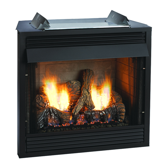
Comfort Systems
Deluxe Vent-Free Universal Fireboxes
ANSI Z21.91 Ventless Fireplace Enclosures for Gas Fired
Decorative Type Unvented Room Heaters
WARNING: If the information in these instructions are
not followed exactly, a fire or explosion may result caus-
ing property damage, personal injury or loss of life.
— Do not store or use gasoline or other flammable vapors
and liquids in the vicinity of this or any other appli-
ance.
— WHAT TO DO IF YOU SMELL GAS
•
Do not try to light any appliance.
•
Do not touch any electrical switch; do not use any
phone in your building.
•
Immediately call your gas supplier from a neigh-
bor's phone. Follow the gas supplier's instruc-
tions.
•
If you cannot reach your gas supplier, call the fire
department.
— Installation and service must be performed by a quali-
fied installer, service agency or the gas supplier.
DO NOT ATTEMPT TO MODIFY OR ALTER THE
CONSTRUCTION OF THE FIREBOX OR ITS COMPO-
NENTS. ANY MODIFICATION OR ALTERATION OF
CONSTRUCTION MAY VOID THE WARRANTY OF
THIS FIREBOX.
CHILDREN AND ADULTS SHOULD BE ALERTED TO
THE HAZARDS OF HIGH SURFACE TEMPERATURE
AND SHOULD STAY AWAY TO AVOID BURNS OR
CLOTHING IGNITION.
YOUNG CHILDREN SHOULD BE CAREFULLY SU-
PERVISED WHEN THEY ARE IN THE SAME ROOM
AS THE FIREBOX.
INSTALLATION INSTRUCTIONS
AND OWNER'S MANUAL
GAS-FIRED
UNIVERSAL FIREBOX FOR
ALL VENT-FREE LOG SETS
MODELS
VFD32FB0L-2
VFD36FB0L-2
VFD32FB2CL-2
VFD36FB2CL-2
VFD32FB2DL-2
VFD36FB2DL-2
VFD32FB2ML-4 VFD36FB2ML-4
VFD32FB0F-2
VFD36FB0F-2
VFD32FB2CF-2
VFD36FB2CF-2
VFD32FB2DF-2
VFD36FB2DF-2
VFD32FB2MF-4
VFD36FB2MF-4
Installer:
Leave this manual with the appliance.
Consumer: Retain this manual for future reference.
FOR USE ONLY WITH A LISTED GAS-FIRED
UNVENTED DECORATIVE ROOM HEATER NOT TO
EXCEED 40,000 BTU/H.
DO NOT BUILD A WOOD FIRE.
WARNING: Improper installation, adjustment, alteration,
service or maintenance can cause injury or property damage.
Refer to this manual. For assistance or additional informa-
tion, consult a qualified installer, service agency or the gas
supplier.
Carefully r eview t he i nstructions s upplied w ith t he d ecorative
type unvented room heater for the minimum fireplace size
requirement.
DO NOT INSTALL A VENT-FREE LOG SET IN THIS
FIREBOX, UNLESS THIS FIREBOX MEETS THE
MINIMUM DIMENSIONS REQUIRED FOR THE
INSTALLATION.
VFD42FB0L-2
VFD42FB2CL-2
VFD42FB2DL-2
VFD42FB2ML-4
VFD42FB0F-2
VFD42FB2CF-2
VFD42FB2DF-2
VFD42FB2MF-4
Page 1
Advertisement
Table of Contents

Related Manuals for Empire Comfort Systems VFD32FB0L-2


Summary of Contents for Empire Comfort Systems VFD32FB0L-2
- Page 1 INSTALLATION INSTRUCTIONS EMPIRE EMPIRE AND OWNER'S MANUAL UNIVERSAL FIREBOX FOR Comfort Systems ALL VENT-FREE LOG SETS Deluxe Vent-Free Universal Fireboxes MODELS VFD32FB0L-2 VFD36FB0L-2 VFD42FB0L-2 VFD32FB2CL-2 VFD36FB2CL-2 VFD42FB2CL-2 VFD32FB2DL-2 VFD36FB2DL-2 VFD42FB2DL-2 VFD32FB2ML-4 VFD36FB2ML-4 VFD42FB2ML-4 VFD32FB0F-2 VFD36FB0F-2 VFD42FB0F-2 VFD32FB2CF-2 VFD36FB2CF-2 VFD42FB2CF-2 VFD32FB2DF-2...
-
Page 2: Table Of Contents
TABLE OF CONTENTS SECTION PAGE Important Safety Information ....................3 Introduction ..........................3 Clearances .......................... 4-5 Firebox Installation Instructions ..................6-8 Installing Hood ........................8-9 Gas Line Connection ......................9 Optional Fresh Air Kit Installation Instructions ............. 10-12 Optional Single Speed Blower Installations Instructions ..........13-15 Junction Box Wiring Installation Instructions ..............16 Maintenance .........................16 Parts List ..........................17... -
Page 3: Important Safety Information
IMPORTANT SAFETY INFORMATION The installation must conform with local codes or, in Any safety screen or guard removed for servicing an the absence of local codes, with the National Fuel Gas appliance must be replaced prior to operating the ap- Code, ANSI Z223.1 (latest edition) and to the National pliance. Provide adequate combustion and ventilation electrical Code, ANSI/NFPA70 (latest edition). air. NOTE: Installation and repair should be done by a quali- The flow of combustion and ventilation air MUST NOT fied service person. The appliance should be inspected be obstructed. before use and at least annually by a qualified service Provide adequate clearance around air openings into person. More frequent cleaning may be required due to the combustion chamber and adequate accessibility excessive lint from carpeting, bedding material, etc. It clearance for servicing and proper operation. -
Page 4: Clearances
CLEARANCES Sidewall Clearances: The clearance from the inside of the firebox COMBUSTIBLE 2 X 4 to perpendicular combustible side wall should not be less than FINISHED WALL HEADER OR MANTEL 6". See Figure 1. Firebox Side and Back Clearances: The firebox outer casing side FINISHED WITH TRIM KIT OR and back flanges are zero clearance to combustibles. NON-COMBUSTIBLE MATERIAL AS DESIRED. Top Framing and Finishing: Combustible framing may rest on STAND OFF top of standoffs. Combustible finishing materials may extend to the top standoff screws on the front edge of the outer wrap. -
Page 5: Clearances
CLEARANCES Ceiling Clearances: The ceiling height should not be less than 42" from the top of the hood. See Figures 3a and 3b. Mantel Clearances: Vent free firebox models must use the hood supplied with the firebox, or one of the optional hood kits available for each model. If a combustible mantel is installed, it must meet the clearance requirements detailed below. Grate Clearance: The minimum clearance between the front legs of the grate and front edge of the firebox is 2". -
Page 6: Firebox Installation Instructions
FIREBOX INSTALLATION INSTRUCTIONS Any vent-free Gas Log Heater must be “For use with approved At this point, you should have decided what components to include ANSI Z21.11.2 unvented room heater.” in your installation, and where the firebox is to be located. If this has not been done, stop and consult your dealer for assistance with Follow and complete the installation instructions of the gas log set this planning. - Page 7 FIREBOX INSTALLATION INSTRUCTIONS (continued) DELUXE DELUXE LOUVERED FLUSH DELUXE LOUVERED FLUSH REFERENCE LETTER VFD32 VFD36 VFD42 VFD32 VFD36 VFD42 35 5/8" 37 5/8" 37 5/8" 35 5/8" 37 5/8" 37 5/8" 34 1/2" 39 1/2" 43 1/2" 34 1/2" 39 1/2" 43 1/2" 17 7/16" 19 13/16" 19 13/16" 17 7/16" 19 13/16" 19 13/16" 29" 33" 37" 29"...
-
Page 8: Installing Hood
FIREBOX INSTALLATION INSTRUCTIONS (continued) Locating Firebox Place firebox in framing opening. Use the four (4) framing brackets provided on the firebox to attach firebox to framing. Different hole locations can be used for finishing materials with thicknesses of 3/8", 1/2" and 3/4". Attach these materials with screws provided, two (2) per framing bracket. See Figure 8. Framing brackets should fit directly against framing material. Use at least one (1) nail per bracket to secure in place. FIREBOX OPENING Check squareness of the firebox prior to securing to framed opening. See Figure 9. CHECK TO SEE THAT BOX IS SQUARE ATTACH (4) FRAMING BRACKETS PRIOR TO ATTACHING TO... -
Page 9: Gas Line Connection
INSTALLING HOOD (continued) Extended Hoods If your non-combustible facing material is over 1" in thickness that will be used to finish this firebox, an extended hood is available that will extend out 2" farther out into the room. Contact your local dealer for details. VB4H32BL Standard Black VB4H36BL Standard Black VB4H42BL Standard Black VB4H32BR Polished Brass VB4H36BR Polished Brass VB4H42BR Polished Brass VB4H32SS Stainless Steel VB4H36SS Stainless Steel VB4H42SS Stainless Steel VB4H32HP Hammered Pewter VB4H36HP Hammered Pewter VB4H42HP Hammered Pewter Finishing All joints (top, bottom and sides), where the wall or decorative facing material meets the firebox surround should be sealed with a non-... -
Page 10: Optional Fresh Air Kit Installation Instructions
OPTIONAL FRESH AIR KIT INSTALLATION INSTRUCTIONS FOR DELUXE AND PREMIUM FIREBOXES The optional BVA1 Fresh Air Kit is designed to introduce outside air to the fireplace or firebox as desired. It must be installed prior to, or at the time of fireplace or firebox installation to framing. The Fresh Air kit must be installed prior to the installation of wall- board or other finishing materials around the unit. - Page 11 the control rod around until the inside end of the rod is mated of the Air Door. The control lever should open the air door with the hole in the front flange of the movable air door. See when rotated upward, and can be locked open by pulling for- Figure 18. ward into the notch at the top of the control lever bracket. 10.
-
Page 12: Optional Fresh Air Kit Installation Instructions
OPTIONAL FRESH AIR KIT INSTALLATION INSTRUCTIONS FOR DELUXE AND PREMIUM FIREBOXES Completion of Air Kit installation OUTSIDE PLATE/VENT 1. Determine the length of 4” Dia. rigid or flex duct connector SCREEN ASSEMBLY AIR DOOR (installer supplied) you will need from the firebox/fireplace ASSEMBLY to the exterior surface of the outside wall, where the air kit hood will be installed. Add a few extra inches to the length to allow for easier attachment of the outside duct connection prior to securing the outside rain cap hood to the building. -
Page 13: Optional Single Speed Blower Installations Instructions
OPTIONAL SINGLE SPEED BLOWER INSTALLATION INSTRUCTIONS Attention: Install blower assembly before connecting gas inlet A factory installed junction box is located on the lower right supply line. side of the firebox. Wiring must be fed to the junction box Wiring and attached to the receptacle that is provided. From right The appliance, when installed, must be electrically grounded in side of the firebox, remove the screw securing the junction accordance with local codes or, in the absence of local codes, box assembly. - Page 14 OPTIONAL SINGLE SPEED BLOWER INSTALLATION INSTRUCTIONS 4. Insert blower assembly into interior, bottom of firebox. Posi- 8. One fan control wire will have a 1/4” female terminal that tion blower assembly so that you align the notch on back of must be attached to the open terminal on the blower motor. See Figure 31, Connection A.
-
Page 15: Optional Single Speed Blower Installations Instructions
OPTIONAL SINGLE SPEED BLOWER INSTALLATION INSTRUCTIONS Blower Motor 110 VOLT AC The blower motor does not have oiling holes. Do not attempt to JUNCTION BOX oil the blower motor. FAN/MOTOR ASSEMBLY Blower Wheels The blower wheels will collect lint and could require periodic cleaning. -
Page 16: Junction Box Wiring Installation Instructions
JUNCTION BOX WIRING INSTALLATION INSTRUCTIONS CAUTION: ALL WIRING SHOULD BE DONE BY A QUALIFIED ELECTRICIAN AND SHALL BE IN COMPLIANCE WITH ALL LOCAL, CITY AND STATE BUILDING CODES. BEFORE MAKING THE ELECTRICAL CONNECTION, MAKE SURE THAT MAIN POWER SUPPLY IS DISCONNECTED. THE APPLIANCE, WHEN INSTALLED, MUST BE ELECTRICALLY GROUNDED IN ACCORDANCE WITH LOCAL CODES OR, IN THE ABSENCE OF LOCAL CODES, WITH THE NATIONAL ELECTRICAL CODE ANSI/NFPA 70 (LATEST EDITION) A factory installed junction box is located on the lower right hand side of the firebox. Wiring must be fed to the junction box and attached to the receptacle that is provided. -
Page 17: Parts List
PARTS LIST Part No. Index No. Description VFD32FB VFD36FB VFD42FB 17149 17247 17247 Top Standoff (Qty 2) 17169 18807 17187 Upper Louver 10554 10554 10554 Framing Bracket (Qty 4) 17170 18808 17188 Lower Louver 17162 17162 17162 Junction Box Assembly R3492 R3492 R3492 Recepticle... -
Page 18: Parts View
PARTS VIEW Page 18 25476-3-1011... -
Page 19: Accessories
ACCESSORIES Accessory Description Model Numbers Fan Kit Designed to provide forced air flow. FBB5 Variable Speed Control Kit Wall mounted variable speed control for use with SCV-1 FBB5 blower Brick Liners Contact dealer for all available Deluxe Firebox optional liner kits Fresh Air Kit Deluxe and Premium Fireboxes BVA-1 Frame Kits 3-Piece Frame Kits Contact dealer for all available Black, Stainless Steel or Hammered Pewter... - Page 20 ACCESSORIES (continued) Extended 4" Hoods Extended hoods that extend out 2" farther than the standard hoods, to accommodate thicker surround materials. Contact dealer for all available optional hood accessories Available as optional kits in Brass, Hammered Pewter, and Stainless Steel finishes. Louvers Styles include Slat, Mission, Arch, and Leaf Patterns. Contact dealer for all available Available as optional kits in Brass, Hammered Pewter, and optional louver accessories Stainless Steel finishes.
-
Page 21: Master Parts Distributor List
For the current list, please click on the Master Parts button at www.empirecomfort.com. Please note: Master Parts Distributors are independent businesses that stock the most commonly ordered Original Equipment repair parts for Heaters, Grills, and Fireplaces manufactured by Empire Comfort Systems Inc. Star-Fire Distributors... -
Page 22: Appliance Service History
APPLIANCE SERVICE HISTORY Date Dealer Name Service Technician Name Service Performed/Notes Page 22 25476-3-1011... - Page 23 APPLIANCE SERVICE HISTORY Date Dealer Name Service Technician Name Service Performed/Notes 25476-3-1011 Page 23...
- Page 24 Empire Comfort Systems Inc. EMPIRE EMPIRE 918 Freeburg Ave. Belleville, IL 62220 If you have a general question about our products, please e-mail us at info@empirecomfort.com. If you have a service or repair question, please contact your dealer. Comfort Systems www.empirecomfort.com...