Table of Contents
Advertisement
Advertisement
Table of Contents

Related Manuals for ECS G33T-M2


Summary of Contents for ECS G33T-M2
- Page 3 Preface Copyright This publication, including all photographs, illustrations and software, is protected under international copyright laws, with all rights reserved. Neither this manual, nor any of the material contained herein, may be reproduced without written consent of the author. Version 1.0 Disclaimer The information in this document is subject to change without notice.
-
Page 4: Declaration Of Conformity
Declaration of Conformity This device complies with part 15 of the FCC rules. Operation is subject to the following conditions: • This device may not cause harmful interference, and • This device must accept any interference received, including interference that may cause undesired operation Canadian Department of Communications This class B digital apparatus meets all requirements of the Canadian Interference-causing Equipment Regulations. -
Page 5: Table Of Contents
T T T T T ABLE OF CONTENTS ABLE OF CONTENTS ABLE OF CONTENTS ABLE OF CONTENTS ABLE OF CONTENTS Preface Chapter 1 Introducing the Motherboard Introduction....................1 Feature......................2 Motherboard Components................4 7 7 7 7 7 Chapter 2 Installing the Motherboard Safety Precautions..................7 Choosing a Computer Case...............7 Installing the Motherboard in a Case............7... - Page 6 Integrated Peripherals..............33 Power Management Setup............34 PCI/PnP Configurations..............35 PC Health Status................36 Frequency/Voltage Control............37 Load Default Settings..............38 Supervisor Password..............38 User Password................39 Save & Exit Setup.................39 Exit Without Saving...............39 Chapter 4 Using the Motherboard Software About the Software CD-ROM..............41 Auto-installing under Windows 2000/XP..........41 Running Setup................42 Manual Installation..................44 Utility Software Reference...............44...
-
Page 7: Introducing The Motherboard
Chapter 1 Introducing the Motherboard Introduction Thank you for choosing the G33T-M2 motherboard. This motherboard is a high perfor- ® mance, enhanced function motherboard designed to support the LGA775 socket for Intel Wolfdale/ Core 2 Duo processors for high-end business or personal desktop markets. -
Page 8: Feature
Feature Processor ® The motherboard uses a LGA775 type of Intel Wolfdale/Core 2 Duo that carries the following features: ® • Accommodates Intel Wolfdale/ Core 2 Duo processors • Supports a system bus (FSB) of 1333/1066/800 MHz • Supports “Hyper-Threading” technology CPU “Hyper-Threading”... - Page 9 1394a FireWire (Optional) • Compliant with single chip hostcontroller for IEEE Std 1394-1995 and IEEE 1394a-2000 • Integrated 400 Mbit 2-Port PHY for the PCI BUS • 3.3V Power Supply with 5V Tolerant Inputs Onboard LAN (Optional) The onboard LAN controller provides the following features: •...
-
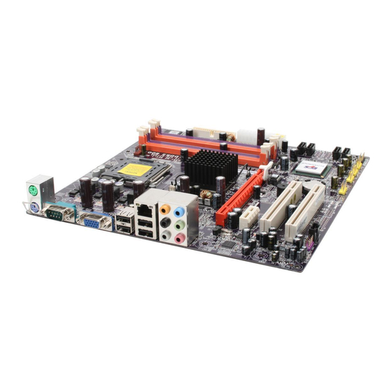
Page 10: Motherboard Components
Motherboard Components Introducing the Motherboard... - Page 11 Table of Motherboard Components LABEL COMPONENTS ® LGA775 socket for Intel Wolfdale /Core 1. CPU Socket CPUs CPU cooling fan connector 2. CPU_FAN 3. DIMM1~4 240-pin DDR2 SDRAM slots 4. FDD Floppy disk drive connector Standard 24-pin ATX power connector 5.
- Page 12 Memo Introducing the Motherboard...
-
Page 13: Installing The Motherboard
Chapter 2 Installing the Motherboard Safety Precautions • Follow these safety precautions when installing the motherboard • Wear a grounding strap attached to a grounded device to avoid damage from static electricity • Discharge static electricity by touching the metal case of a safely grounded object before working on the motherboard •... -
Page 14: Checking Jumper Settings
Do not over-tighten the screws as this can stress the motherboard. Checking Jumper Settings This section explains how to set jumpers for correct configuration of the motherboard. Setting Jumpers Use the motherboard jumpers to set system configuration options. Jumpers with more than one pin are numbered. -
Page 15: Checking Jumper Settings
Checking Jumper Settings The following illustration shows the location of the motherboard jumpers. Pin 1 is labeled. Jumper Settings Type Jumper Description Setting (default) 1-2: NORMAL 2-3: CLEAR CMOS CLR_CMOS 3-pin CLR_CMOS Before clearing the CMOS, make sure to CLR_CMOS turn off the system. -
Page 16: Connecting Case Components
Connecting Case Components After you have installed the motherboard into a case, you can begin con- necting the motherboard components. Refer to the following: Connect the CPU cooling fan cable to CPU_FAN Connect the system cooling fan connector to SYS_FAN Connect the case switches and indicator LEDs to the PANEL1. -
Page 17: Atx 24-Pin Power Connector
CPU_FAN: FAN Power Connector Signal Name Function System Ground Power +12V +12V Sense Sensor CPU FAN control Users please note that the fan connector supports the CPU cooling fan of 1.1A ~ 2.2A (26.4W max) at +12V. SYS_FAN: FAN Power Connector Signal Name Function System Ground... -
Page 18: Front Panel Header
Front Panel Header The front panel header (PANEL1) provides a standard set of switch and LED headers commonly found on ATX or Micro ATX cases. Refer to the table below for information: Signal Function Signal Function HD_LED_P Hard disk LED(+) FP PWR/SLP *MSG LED (+) HD_LED_N Hard disk LED (-) FP PWR/SLP *MSG LED (-) -
Page 19: Installing Hardware
Installing Hardware Installing the Processor Caution: When installing a CPU heatsink and cooling fan make sure that you DO NOT scratch the motherboard or any of the surface-mount resistors with the clip of the cooling fan. If the clip of the cooling fan scrapes across the motherboard, you may cause serious damage to the motherboard or its components. -
Page 20: Cpu Installation Procedure
CPU Installation Procedure The following illustration shows CPU installation components. A. Read and follow the instructions shown on the sticker on the CPU cap. B. Unload the cap · Use thumb & forefinger to hold the lifting tab of the cap. ·... -
Page 21: Installing Memory Modules
Installing Memory Modules This motherboard accomodates four memory modules. It can support four 240-pin DDR2 800/667. The total memory capacity is 8 GB. DDR2 SDRAM memory module table Memory Bus Memory module 333 MHz DDR2 667 DDR2 800 400 MHz You must install at least one module in any of the four slots. - Page 22 Table A: DDR2(memory module) QVL (Qualified Vendor List) The following DDR2 667/800 memory modules have been tested and qualified for use with this motherboard. Type Size Vendor Module Name Infineon HYS64T325001HU-3-A 256MB Ramaxel 5NB31 D9DCG A-DATA AD29608A88-3EG A-DATA Eipida E5108AE-6E-E A-DATA E5108AE-6E-E CORSAIR...
-
Page 23: Installing A Hard Disk Drive/Cd-Rom/Sata Hard Drive
Installing SATA Hard Drive About SATA Connectors Your motherboard features four SATA connectors supporting a total of four drives. SATA refers to Serial ATA (Advanced Technology Attachment) is the standard interface for the IDE hard drives which are currently used in most PCs. These connectors are well designed and will only fit in one orientation. - Page 24 FDD: Floppy Disk Connector This connector supports the provided floppy drive ribbon cable. After connecting the single end to the onboard floppy connector, connect the remaining plugs on the other end to the floppy drives correspondingly. Installing the Motherboard...
-
Page 25: Installing Add-On Cards
Installing Add-on Cards The slots on this motherboard are designed to hold expansion cards and connect them to the system bus. Expansion slots are a means of adding or enhancing the motherboard’s features and capabilities. With these efficient facilities, you can increase the motherboard’s capabili- ties by adding hardware that performs tasks that are not part of the basic system. -
Page 26: Connecting Optional Devices
Follow these instructions to install an add-on card: Remove a blanking plate from the system case corresponding to the slot you are going to use. Install the edge connector of the add-on card into the expansion slot. Ensure that the edge connector is correctly seated in the slot. Secure the metal bracket of the card to the system case with a screw. - Page 27 AUDIO1: Front Panel Audio header for Azalia This header allows the user to install auxiliary front-oriented microphone and line-out ports for easier access. Signal Name Signal Name PORT 1L AUD_GND PORT 1R PRESENCE# PORT 2R SENSE1_RETURN SENSE_SEND PORT 2L SENSE2_RETURN SATA1/2/5/6: Serial ATA connectors These connectors are use to support the new Serial ATA devices for the highest date transfer rates (3.0 Gb/s), simpler disk drive cabling and easier PC assembly.
- Page 28 1394A1: IEEE 1394A header (Optional) Connect this header to any device with IEEE 1394a interface. Signal Name Signal Name Signal Name Function TPA+ TPA- TPB+ TPB- Cable-Power Cable-Power Key Pin COM2: Onboard serial port connector (optional) Connect a serial port extension bracket to this header to add a second serial port to your system.
- Page 29 CD_IN: Analog Audio Input connector Signal Name Function CD_L CD In left channel Ground Ground CD_R CD In right channel SPDIF_OUT1: SPDIF out header This is an optional header that provides an SPDIFO (Sony/Philips Digital Interface) output to digital multimedia device through optical fiber or coxial connector. Signal Name SPDIFOUT Signal Name...
-
Page 30: Connecting I/O Devices
Connecting I/O Devices The backplane of the motherboard has the following I/O ports: (optional) (optional) PS2 Mouse Use the upper PS/2 port to connect a PS/2 pointing device. PS2 Keyboard Use the lower PS/2 port to connect a PS/2 keyboard. Parallel Port (LPT1) Use LPT1 to connect printers or other parallel communications (optional) devices. -
Page 31: Using Bios
Chapter 3 Using BIOS About the Setup Utility The computer uses the latest “American Megatrends Inc. ” BIOS with support for Windows Plug and Play. The CMOS chip on the motherboard contains the ROM setup instructions for configuring the motherboard BIOS. The BIOS (Basic Input and Output System) Setup Utility displays the system’s configura- tion status and provides you with options to set system parameters. -
Page 32: Bios Navigation Keys
Press DEL to enter SETUP Press the delete key to access the BIOS Setup Utility. CMOS Setup Utility -- Copyright (C) 1985-2005, American Megatrends, Inc. Standard CMOS Setup Frequency/Voltage Control Advanced Setup Load Default Settings Advanced Chipset Setup Supervisor Password Integrated Peripherals User Password Power Management Setup... -
Page 33: Updating The Bios
Updating the BIOS You can download and install updated BIOS for this motherboard from the manufacturer’s Web site. New BIOS provides support for new peripherals, improvements in performance, or fixes for known bugs. Install new BIOS as follows: If your motherboard has a BIOS protection jumper, change the setting to allow BIOS flashing. -
Page 34: Standard Cmos Setup
Standard CMOS Setup This option displays basic information about your system. CMOS Setup Utility -- Copyright (C) 1985-2005, American Megatrends, Inc. Standard CMOS Setup Date Mon 03/26/2007 Help Item Time 00 : 01 : 56 User [Enter], [TAB] SATA1 Not Detected or [SHIFT-TAB] to SATA 2 Not Detected... - Page 35 Type (Auto) Use this item to configure the type of the IDE device that you specify. If the feature is enabled, it will enhance hard disk performance by reading or writing more data during each transfer LBA/Large Mode (Auto) Use this item to set the LAB/Large mode to enhance hard disk performance by optimizing the area the hard disk is visited each time.
-
Page 36: Advanced Setup
Advanced Setup This page sets up more advanced information about your system. Handle this page with caution. Any changes can affect the operation of your computer. CMOS Setup Utility - Copyright (C) 1985-2005, American Megatrends, Inc. Advanced Setup Thermal Management Enabled Help Item Thermal Management... - Page 37 1st/2nd3rd Boot Device (Maxtor 6V080E0/CD/DVD/1st FLOPPY DRIVE) Use this item to determine the device order the computer used to look for an operating system to load at start-up time. The devices showed here will be different depending on the exact devices installed on your motherboard. Hard Disk Drives (Press Enter) Scroll to this item and press <Enter>...
-
Page 38: Advanced Chipset Setup
Advanced Chipset Setup This page sets up more advanced information about your system. Handle this page with caution. Any changes can affect the operation of your computer. CMOS Setup Utility - Copyright (C) 1985-2005, American Megatrends, Inc. Advanced Chipset Setup DRAM Frequency Auto Help Item... -
Page 39: Integrated Peripherals
Integrated Peripherals This page sets up some parameters for peripheral devices connected to the system. CMOS Setup Utility - Copyright (C) 1985-2005, American Megatrends, Inc. Integrated Peripherals Onboard Floppy Controller Enabled Help Item Serial Port1 Address 3F8&IRQ4 Serial Port2 Address 2F8/IRQ3 Allows BIOS to Enable Serial Port2 Mode... -
Page 40: Power Management Setup
OnBoard LAN Boot ROM (Disabled) Use this item to enable or disable the booting from the onboard LAN or a network add-in card with a remote boot ROM installed. USB Functions (Enabled) Use this item to enable or disable the USB function. Legacy USB Support (Enabled) Use this item to enable or disable support for legacy USB devices. -
Page 41: Pci/Pnp Configurations
Wake-Up by PME (Disabled) The system can be turned off with a software command. If you enable this item, the system can automatically resume if there is an incoming call on the PCI Modem or PCI LAN card. You must use an ATX power supply in order to use this feature. Use this item to do wake-up action if inserting the PCI card. -
Page 42: Pc Health Status
Allocate IRQ to PCI VGA (Yes) If this item is enabled, an IRQ will be assigned to the PCI VGA graphics system. You set this value to No to free up an IRQ. Press <Esc> to return to the main menu setting page. PC Health Status On motherboards support hardware monitoring, this item lets you monitor the parameters for critical voltages, temperatures and fan speeds. -
Page 43: Frequency/Voltage Control
System Component Characteristics These items display the monitoring of the overall inboard hardware health events, such as System & CPU temperature, CPU & DIMM voltage, CPU & system fan speed,...etc. • CPU Vcore • NB Vcore • VDIMM • CPU/System Fan Speed •... -
Page 44: Load Default Settings
Spread Spectrum (Enabled) If you enable spread spectrum, it can significantly reduce the EMI (Electro-Magnetic Interference) generated by the system. Memory Voltage (1.9V) This item allows users to adjust the DDR memory voltage. Press <Esc> to return to the main menu setting page. Load Default Settings This option opens a dialog box that lets you install optimized defaults for all appropriate items in the Setup Utility. -
Page 45: User Password
User Password This page helps you install or change a password. CMOS Setup Utility - Copyright (C) 1985-2005, American Megatrends, Inc. User Password User Password : Not Installed Help item Change User Password Press Enter Install or Change the password. : Move Enter : Select +/-/: Value... - Page 46 Memo Using BIOS...
-
Page 47: Using The Motherboard Software
Chapter 4 Using the Motherboard Software About the Software CD-ROM The support software CD-ROM that is included in the motherboard package contains all the drivers and utility programs needed to properly run the bundled products. Below you can find a brief description of each software program, and the location for your motherboard version. -
Page 48: Running Setup
Setup Tab Setup Click the Setup button to run the software installation program. Select from the menu which software you want to install. Browse CD The Browse CD button is the standard Windows command that allows you to open Windows Explorer and show the contents of the support Before installing the software from Windows Explorer, look for a file named README.TXT, INSTALL.TXT or something similar. - Page 49 Click Next. The following screen appears: Check the box next to the items you want to install. The default options are recommended. Click Next run the Installation Wizard. An item installation screen appears: Follow the instructions on the screen to install the items. Drivers and software are automatically installed in sequence.
-
Page 50: Manual Installation
Manual Installation Insert the CD in the CD-ROM drive and locate the PATH.DOC file in the root directory. This file contains the information needed to locate the drivers for your motherboard. Look for the chipset and motherboard model; then browse to the directory and path to begin installing the drivers.