Table of Contents
Advertisement
Quick Links
Advertisement
Table of Contents

Related Manuals for Supero Supero SC743


Summary of Contents for Supero Supero SC743
- Page 1 SC743 CHASSIS USER'S GUIDE 1.1b...
- Page 2 Santa Clara County in the State of California, USA. The State of California, County of Santa Clara shall be the exclusive venue for the resolution of any such disputes. Supermicro's total liability for all claims will not exceed the price paid for the hardware product. Revision : 1.1b Release Date: Jan.
-
Page 3: Table Of Contents
Chapter 1: Safety Information and Technical Specifications Table of Contents Chapter I: Safety Information and Technical Specifications ..1-4 1-1. Electrical Safety Guidelines ............. 1-4 1-2. General Safety Guidelines ............... 1-5 1-3. ESD Safety Guidelines ............... 1-6 1-4. Operation Safety Guidelines ............1-6 1-5. -
Page 4: Chapter I: Safety Information And Technical Specifications
SC743 Chassis User’s Guide Chapter 1-Safety Information and Technical Specifications 1-1 Electrical Safety Guidelines Warning: To avoid electrical shock, check the power cords as follows: Checking the Power Cords Use the exact type of power cords as required. Be sure to use power cord(s) that came with safety certifications. The power cord(s) must be compliant with the AC voltage requirements in your region. -
Page 5: General Safety Guidelines
Chapter 1: Safety Information and Technical Specifications Use rubber mats specifically designed as electrical insulators when working with computer systems. The power supply or power cord must include a grounding plug and must be plugged into grounded outlets. Motherboard Battery: CAUTION -Make sure not to install the onboard battery upside down to avoid possible explosion. -
Page 6: Esd Safety Guidelines
SC743 Chassis User’s Guide 1-3 ESD Safety Guidelines Electric Static Discharge (ESD) can damage electronic com- ponents. To prevent damage to your system board, it is important to handle it very carefully. The following measures are generally sufficient to protect your equipment from ESD. Use a grounded wrist strap designed to prevent static discharge. - Page 7 Chapter 1: Safety Information and Technical Specifications To avoid personal injury and property damage, please carefully STOP follow all the safety steps listed below: Before accessing the chassis: 1. Turn off all peripheral devices connected to the SC743. 2. Press the power button to power off the system. 3.
-
Page 8: Product Compliance Information
SC743 Chassis User’s Guide Before installing the chassis into a rack: 1. Make sure that the rack is securely anchored onto an unmovable surface or structure before installing the chassis into the rack. 2. Unplug the power cord(s) of the rack before installing the chassis into the rack. - Page 9 Chapter 1: Safety Information and Technical Specifications 1-6A Packing List and Chassis Specifications for the SC743S1/743i Series--Revision A A1. The SC743S1/743i-R760(B) chassis contains the following: Component Quantity Part Number SCA 1” Drive Tray (*SC743S1 only) CSE- PT17 (B) IDE Drive Carriage (*SC743i only) CSE- PT31 (B) 80mm Hot- Swap Chassis Fan FAN-0072...
- Page 10 SC743 Chassis User’s Guide 1-6B Packing List and Chassis Specifications for the SC743S1/743i/SC743S2 Series--Revision B A1. The SC743S1/743i/SC743S2-R760(B) chassis contains: Component Quantity Part Number SCA 1” Drive Tray (*SC743S1 only) CSE-PT17 (B) IDE Driv e Carri age (*SC743i onl y) CSE-PT31 (B) 80mm Hot-Swap Chassis Fan FAN-0072...
- Page 11 Chapter 1: Safety Information and Technical Specifications 1-7A Packing List, Chassis Specifications and Back Panels for the SC743T Series--Revision A A1. The SC743T-760 (B) chassis contains the following: Component Part Number SCA 1” Drive Trays CSEPT17(B) 80mm Hot- Swap Chassis Fan FAN-0072 80mm Hot-Swap Rear Chassis Fan FAN-0073...
- Page 12 SC743 Chassis User’s Guide 1-7B Packing List, Chassis Specifications and Back Panels for the SC743T Series--Revision B A1. The SC743T-760 (B) chassis contains the following: Component Part Number SCA 1” Drive Trays CSEPT17(B) 80mm Hot-Swap Chassis Fan FAN-0072 80mm Hot-Swap Rear Chassis Fan FAN-0081 760W Triple Redundant (2+1) Power PWS-0050...
- Page 13 Chapter 1: Safety Information and Technical Specifications C. SC743 Power Supply Specifications Power supply spec SC743 series Mfr. model # SP762-TS(3xSP382-TS Models) Mfr. part # PWS-0050 Rated AC input voltage 100-240V AC Rated input frequency 50-60 Hz Rated input current 14A (115V) 8A (230V) Rated output power...
- Page 14 SC743 Chassis User’s Guide D. SCSI 743 Back Panel (*SC743S1/SC743S2 Only) D-1 Jumper Settings and Pin Definitions Jumper Default Setting Note JP19 Open Buzzer Reset (*Note Below) (*Note: Press the button on the front panel once to disable the buzzer. If the buzzer has been disabled, please be sure to press the button once again to re-enable the buzzer.) D-2 Jumper Setting Locations SCA743S1...
- Page 15 6) Click “Next” 2 times, uncheck both “Floppy disk drives” and “CD-ROM drives”. Then, select the item- “Specify a location,” and choose “Next”. 7) Click on “Browse” and choose D drive or wherever Supermicro Setup CD is in. 8) Choose “Qlogic” folder and click on “Open”.
- Page 16 SC743 Chassis User’s Guide E. SATA743 Back Panel (*SC 743T Only) E-1 Jumpers and Default Settings Jumper Description Default JP18 Buzzer Reset Open *JP25 Overheat Temperature 50 1-2 (*Note 1) *JP26 Common Act In and Act #0~#7 In Open (*Note 2) (*Note1: Test if the buzzer is beeping to see if the OH temperature is >=50 (*Note2: Test to see if all 8 Activity.
- Page 17 Chapter 1: Safety Information and Technical Specifications E-4 Jumpers/Headers Locations Diagram1: Jumpers and Connectors Locations M T 1 SATA743 REV. 1.01 M M 1 M T 2 +12V GND GND +12V GND GND +5V M T 3 +12V GND +5V 1-17...
- Page 18 SC743 Chassis User’s Guide Notes 1-18...
-
Page 19: Chapter 2: Chassis Description And Installation Procedures
Chapter 2: Chassis Description and Installation Instructions Chapter 2: Chassis Description and Installation Procedures 2-1 Chassis Description A. Contents of the Accessory Kit: The following items are included in the Accessory Kit: B. Flat head 6-32 x 5 mm [0.197] A. -
Page 20: Chassis Front View And The Front Control Panel
SC743 Chassis User’s Guide B. Chassis Front View and the Front Control Panel Chassis Front Panel Front Panel I/O Device Definitions Hot-Swappable Drive Trays (8) Floppy Drive Bay 5.25 Drive Trays (2) Front LED LED Button Definitions Power Button System Reset Power Indicator HDD Activity Indicator E/F. - Page 21 Chapter 2: Chassis Description and Installation Instructions LED Button Descriptions LED Button Color Condition Description Power Green System On System Off HDD Activity Green Blink HDD Activity No Activity LAN Indicators Green Linked Blink LAN Activity Disconnected Overheat/Fan Fail System Overheat Blink Fan Fail System Normal...
-
Page 22: Chassis Rear View And The Back Panel
SC743 Chassis User’s Guide C. Chassis Rear View and the Back Panel SC743 Chassis-Rev. A Rear View Back Panel Devices Power Supply Module Back Panel I/O Ports Rear System Fans Full-size PCI Expansion Slots SC743 Chassis-Rev. B Rear View... - Page 23 Chapter 2: Chassis Description and Installation Instructions *I/O Back Panel Back Panel I/O Port Definitions Keyboard & Mouse USB Ports COM/Video Ports LAN1 & LAN2 Audio (Line-In: top, Line-out: bottom) Microphone Parallel Port (*Note: The actual I/O Configuration of your system might be different from the one shown above.) Power Module LED Descriptions Color Condition...
-
Page 24: Chassis Installation
SC743 Chassis User’s Guide 2-2 Chassis Installation A. Important Safety Guidelines STOP This product shall only be accessed, assembled and serviced by technically qualified personnel or technicians. To avoid personal injury and property damage, please read all the information provided in Chapter 1, and carefully follow all the Safety Guidelines listed before accessing or servicing the SC743 or its components. - Page 25 Chapter 2: Chassis Description and Installation Instructions C. Accessing the Hot-Swappable Drive Tray and Installing a Hard Drive Disk To install the Hot-Swappable drive into the chassis, you need to first remove the Hot-Swappable drive tray from the chassis. Procedures 1.
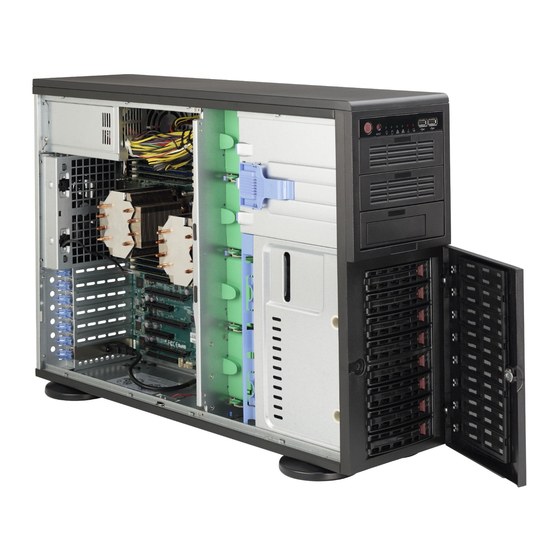
- Page 26 SC743 Chassis User’s Guide D. Removing the Side Cover of the SC743 Chassis Before installing any components, replacing chassis fans or accessing the motherboard, you will first need to remove the side cover. Procedures 1. Press the release tab to unlock the side cover. 2.
- Page 27 Chapter 2: Chassis Description and Installation Instructions E-1. Accessing the Middle chassis fans Before installing the motherboard in the chassis or accessing the motherboard, you will need to remove the front/rear chassis fans, the air shroud from the chassis and install the standoffs on the chassis. Procedures 1.
- Page 28 SC743 Chassis User’s Guide E-2. Removing the Air Shroud Before installing the motherboard into the chassis, you will need to remove the air shroud first. Procedures 1. Press the release tab located on the back side of the middle chassis bracket as shown below until you hear the click.
- Page 29 Chapter 2: Chassis Description and Installation Instructions E-3. Accessing the Rear Chassis Fans Procedures 1. Locate the release tab on the top of the rear chassis fan as shown below. Push the release tab down to unlock the rear chassis fan. 2.
- Page 30 SC743 Chassis User’s Guide F. Accessing the 760W Triple Redundant Power Supply (*Caution: Unplug the Power Cord before removing the Power Supply!!) Procedures 1. Locate the release tab on the left side of the power supply. 2. Push the release tab to the right to release the power supply from its locking position as shown below: 3.
-
Page 31: Installing The Motherboard
Chapter 2: Chassis Description and Installation Instructions G. Installing the Motherboard Be sure to disconnect the power supply before accessing or installing the mother- board in the chassis. To install the motherboard, first, you will need to identify the locations of the processor(s), mounting holes, retention brackets, and then, install the correct type of standoffs, and heatsink retention brackets under the CPU or on the motherboard before installing the motherboard into the chassis. - Page 32 SC743 Chassis User’s Guide SC743 Chassis-Rev. A SC743 Chassis-Rev. B 3. Secure the motherboard to the chassis with Type A(6-32) screws as shown above. (*Please refer to Page 2-1 Motherboard kit for the Type A screw.) 4. Secure the CPU heatsink mechanism to the motherboard. (**Note: the CPUs and Heatsinks shown above are for reference only!! The motherboard is not included in the SC743 shipping package.) Warning: For proper cooling, please make sure that the air shroud and...
-
Page 33: Accessing The Interior Between The Back Panel And The Mid-Plane
Chapter 2: Chassis Description and Installation Instructions H. Access to the Interior between the Back Panel and the Mid- Plane For easy access to the interior between the Back Panel and the Mid-plane, please follow the instructions below before installing components or cables into this area. - Page 34 SC743 Chassis User’s Guide I. Accessing the PCI Slot Brackets to Install PCI Cards After you've installed the motherboard into the chassis, you are ready to install add-on cards, such as PCI cards into the chassis. Before installing PCI cards, please follow the instructions below to access the PCI slot brackets. Procedures 1.
- Page 35 SC743 as a tower. 4. You can also install Supermicro's Mobile Rack CSE-M34T or Mobile Rack CSE- M35S/T1 into the SC743 chassis. To do so, you need to simply remove the storage module and replace it with a Mobile Rack.
- Page 36 SC743 Chassis User’s Guide Procedures 1. Push the buttons on the top cover to unlock it. Once it is unlocked, push the top cover out of the chassis. 2. Remove the screw from each chassis foot. 3. Use a flat head screw driver to gently pry the chassis foot out of the chassis. SC743 Chassis-Rev.
- Page 37 Chapter 2: Chassis Description and Installation Instructions SC743 Chassis-Rev. A 4. Locate the release tab on top of the storage module as shown below. Press the release tab to unlock the storage module. 5. Once the storage module is unlocked, push the module out of the chassis. SC743 Chassis-Rev.
- Page 38 SC743 Chassis User’s Guide To configure the storage module for 5.25" devices 3. Remove the 5.25" drive trays from the storage module, and then, remove the screws and drive tray brackets from the drive trays. 4. Install 5.25" devices into the storage module. Then, install the module back to the chassis.
-
Page 39: Installing The Air Shroud
Chapter 2: Chassis Description and Installation Instructions K. Installing the Air Shroud Warning: For proper cooling, please be sure to install the air shroud and all the chassis covers before you operate the system. Procedures 1. Locate the three guide rails on the reverse side of front fan panel as shown below. -
Page 40: Installing The Chassis Rails
SC743 Chassis User’s Guide L. Installing the Chassis Rails Please make sure that the chassis covers and chassis rails are installed on the chassis before you install the chassis into the rack. To avoid personal injury and property damage, please carefully follow all the safety steps listed below: Before installing the Chassis rails: 1. - Page 41 Chapter 2: Chassis Description and Installation Instructions Procedures to Install the Outer Rails 1. Locate two pairs of outer rails--each pair of outer e rails consist of one middle rail, one end bracket and one end rail as shown below: Middle Rail End Rail End Bracket...
- Page 42 SC743 Chassis User’s Guide Notes 2-24...
- Page 43 Addendum A: Installing the CSE-M34S/CSE-M34T Mobile Rack...
- Page 44 SC743 Chassis User's Guide Table of Contents 1. Packaging List ....................3 2. Technical Specifications ................... 3 3. Jumper Settings ....................4 4. Hardware Installation Procedures ..............6 5. SCSI(Super) GEM Drive Installation Instructions for Windows OS ..8...
-
Page 45: Packing List
Addendum A: Installing Mobile Rack-CSE M34S/T CSE-M34S/CSE-M34T Supermicro’s CSE-M34S/CSE-M34T Mobile Rack Series offers the cutting edge technology with greater flexibility. The CSE-M34T supports four Serial ATA hot-swap hard drives that yield an unparalleled storage capacity with- out compromising productivity by eliminating possible system downtime. The CSE-M34S also accommodates four SCSI SCA 320/160 hard drives which provide configuration flexibility and maximum data integrity. -
Page 46: Jumper Settings
SC743 Chassis User's Guide 3. Jumper Settings A. Jumper Settings for the CSE-M34S (SCSI): Jumper Description Setting JP14 Delay Start Closed: Enable, Open: Disable (*Default) JP18 Buzzer Reset Closed: Enable, Open: Disable (*Default) JP25 Overheat Temperature Open: 50 1-2: 55 C (*Default) 2-3: 60 JP21... - Page 47 Addendum A: Installing Mobile Rack-CSE M34S/T B. Jumper Settings for the CSE-M34T (SATA): Jumper Description Setting JP18 Buzzer Reset Closed: Enable, Open: Disable (*Default) JP25 Overheat Temperature Open: 45 1-2: 50 C (*Default) 2-3: 55 JP28 Fan Sense 1-2: Enabled (if a fan is not present, the alarm will sound) (*Default), 2-3: Disabled JP26...
- Page 48 SC743 Chassis User's Guide 4. Hardware Installation Procedures (*Notes: For the CSE-M34S: 1. SCSI IDs are assigned automatically by the backplane. Do not set IDs manually on the drives. See the previous section for SCSI ID jumper settings. 2. SCSI termination is enabled by default on the SCSI backplane.
- Page 49 Addendum A: Installing Mobile Rack-CSE M34S/T B. Accessing the Drive Backplane: 1. Remove the two screws as shown below: Remove the s c r e w s The CSE-M34T (SATA) Model The CSE-M34S(SCSI) Model 2. Pull out the rear fan bracket as shown below: Pull out the rear fan bracket The CSE-M34S(SCSI) Model...
- Page 50 6) Click “Next” 2 times, uncheck both “Floppy disk drives” and “CD-ROM drives”. Then, select the item- “Specify a location,” and choose “Next”. 7) Click on “Browse” and choose D drive or wherever Supermicro Setup CD is in. 8) Choose “Qlogic” folder and click on “Open”.
- Page 51 Addendum B Installing the CSE-M35S/CSE- M35T1 Mobile Rack...
- Page 52 SC743 Chassis User's Guide Table of Contents Packaging List ...................... 3 Technical Specifications ..................4 Jumper Settings ....................5 Installation Procedures ..................7...
- Page 53 Addendum B: Installing Mobile Rack-CSE M35S/T1 CSE-M35S/CSE-M35T1 Supermicro’s CSE-M35S/CSE-M35T1 Mobile Rack Series offers the cutting edge technology with greater flexibility. The CSE-M35T1 supports five Se- rial ATA hot-swappable hard drives that yield a unparalleled storage capac- ity without compromising productivity by eliminating possible system down- time.
- Page 54 SC743 Chassis User's Guide 2. Technical Specifications Occupancy Three (3) 5.25" Drive Bays Capacity Five (5) 1" SCA Ultra320/160 Hard Drives with SAF-TE built-in (*CSE-M35S only) Five (5) 1" Host Receptacle Connectors, SATA hot-swap hard drives (*CSE-M35T-1 only) Cooling One (1) 9cm Exhaust Fan Subsystem System Fan Fail Detection LED and Alarm...
- Page 55 Addendum B: Installing Mobile Rack-CSE M35S/T1 3. Jumper Settings A. Jumper Settings for the CSE-M35S (SCSI): Jumper Description Setting JP18 Buzzer Reset Closed: Enable, Open: Disable (*Default) JP21 SCSI Termination Closed: Enable (*Default), Open: Disable JP24 SCSI ID Selection 1-2: SCSI Ids: 0,1,2,3,4 (*Default), 2-3: SCSI Ids: 9,10,11,12,13 JP29 GEM 318 IDs...
- Page 56 SC743 Chassis User's Guide B. Jumper Settings for the CSE-M35T1 (SATA): Jumper Description Setting JP18 Buzzer Reset Closed: Enable, Open: Disable (*Default) JP25 Overheat Temperature Open: 45 1-2: 50 C (*Default), 2-3: 55 JP26 Act#1-Act#5 Connect this header to CBL-0057 (SATA LED Cable) JP28: Fan Sense...
-
Page 57: Installation Procedures
Addendum B: Installing Mobile Rack-CSE M35S/T1 4. Installation Procedures (*Note: For the CSE-M35S: 1. SCSI IDs are assigned automatically by the backplane. Do not set IDs manually on the drives. See the previous section for SCSI ID jumper settings. 2. SCSI termination is enabled by default on the SCSI backplane. 3. - Page 58 SC743 Chassis User's Guide 2. Swing the handle outward and pull out the unit (as shown below:) 3. Mount a drive in a carrier (as shown below:)
- Page 59 Addendum B: Installing Mobile Rack-CSE M35S/T1 B. Accessing the Exhaust Fan: 1. Push the tabs located on both sides of the unit (as shown be- low:) 2. Pull out the fan (as shown below:) (*Note: For the SC-743 Chassis, the CSE-M35 Rear Exhaust Fan should not be used.
- Page 60 SC743 Chassis User's Guide C. Accessing the Drive Backplane: 1. Unscrew the screw located on the side of the unit (as shown below:) 2. Pull out the Rear Bracket (as shown below:) 3. Access the Backplane (as shown below:) B-10...