Table of Contents
Advertisement
Quick Links
Download this manual
See also:
User Manual
Advertisement
Table of Contents

Related Manuals for Supero SC747TQ-R1400B


Summary of Contents for Supero SC747TQ-R1400B
- Page 1 UPER ® SC747 CHASSIS Series SC747TQ-R1400B USER’S MANUAL...
- Page 2 SC747 Chassis Manual The information in this User’s Manual has been carefully reviewed and is believed to be accurate. The vendor assumes no responsibility for any inaccuracies that may be contained in this document, makes no commitment to update or to keep current the information in this manual, or to notify any person or organization of the updates.
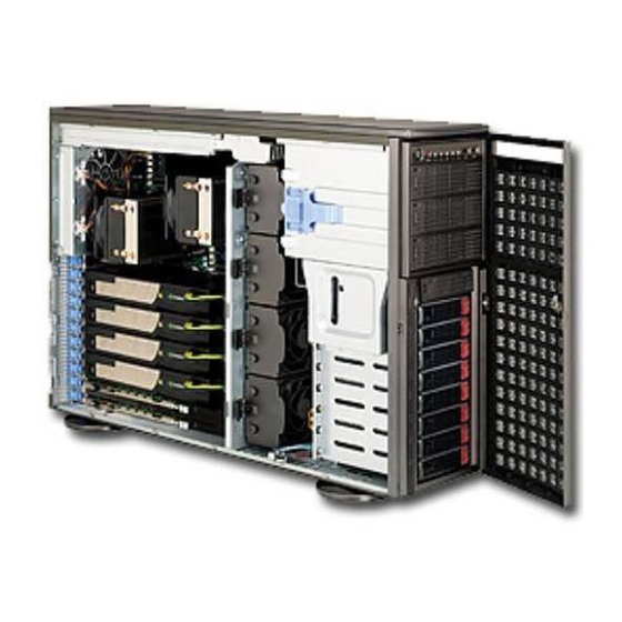
- Page 3 Preface Preface About This Manual This manual is written for professional system integrators and PC technicians. It provides information for the installation and use of the SC747 4U chassis. Installa- tion and maintenance should be performed by experienced technicians only. Supermicro's SC747TQ-R1400 server/workstation chassis is truly industry's most powerful high performance server chassis that offers 11 full-height, full-length PCI-E expansion slots and four sets of 6-pin and 8-pin power connectors to support up...
-
Page 4: Manual Organization
SC747 Chassis Manual Manual Organization Chapter 1: Introduction The first chapter provides a checklist of the main components included with this chassis and describes the main features of the SC747 chassis. This chapter also includes contact information. Chapter 2: System Safety This chapter lists warnings, precautions, and system safety. -
Page 5: Appendices
Preface Appendices This section lists compatible cables, power supply specifications, and compatible backplanes. Not all compatible backplanes are listed. Refer to our Web site for the latest compatible backplane information. Appendix A: Chassis Cables Appendix B: Power Supply Specifications Appendix C: SAS-747TQ Backplane Manual... -
Page 6: Table Of Contents
SC747 Chassis Manual Table of Contents Preface ......................iii About This Manual ..................... iii Manual Organization ..................iv Appendices ......................v Chapter 1 Introduction ................1-1 Overview ......................1-1 Shipping List ....................1-1 Chassis Features .................... 1-2 CPU ......................... 1-2 Hard Drives ..................... 1-2 I/O Expansion slots .................. - Page 7 Preface Chapter 5 Chassis Setup and Maintenance ........... 5-1 Overview ......................5-1 Installation and Maintenance ................5-1 Installation Procedures ..................5-1 General Maintenance ..................5-1 Chassis Covers ....................5-2 Removing the Main Cover ................5-3 Opening the Front Cover ................5-4 Configuring the the Storage Module ..............
- Page 8 SC747 Chassis Manual Notes viii...
-
Page 9: Chapter 1 Introduction
Chapter 1: Introduction Chapter 1 Introduction Overview Supermicro’s SC747 4U chassis features a unique and highly-optimized design. The chassis is equipped with high efficiency power supply. High performance fans provide ample optimized cooling for FB-DIMM memory modules and 8 hot-swap drive bays offer maximum storage capacity in a 4U form factor. -
Page 10: Chassis Features
SC747 Chassis Manual Chassis Features The SC747 4U high-performance chassis includes the following features: The SC747 Chassis supports a DP/UP processor. Please refer to the motherboard specifications pages on our web site for updates on supported processors. Hard Drives The SC747 Chassis features eight slots for SAS/SATA drives. These drives are hot -swappable. -
Page 11: Contacting Supermicro
Chapter 1: Introduction Contacting Supermicro Headquarters Address: Super Micro Computer, Inc. 980 Rock Ave. San Jose, CA 95131 U.S.A. Tel: +1 (408) 503-8000 Fax: +1 (408) 503-8008 Email: marketing@supermicro.com (General Information) support@supermicro.com (Technical Support) Web Site: www.supermicro.com Europe Address: Super Micro Computer B.V. Het Sterrenbeeld 28, 5215 ML 's-Hertogenbosch, The Netherlands Tel:... - Page 12 SC747 Chassis Manual Notes...
-
Page 13: Chapter 2 System Safety
Chapter 2: System Safety Chapter 2 System Safety Overview This chapter provides a quick setup checklist to get your chassis up and running. Following the steps in order given should enable you to have your chassis set up and operational within a minimal amount of time. This quick set up assumes that you are an experienced technician, familiar with common concepts and terminology. -
Page 14: Electrical Safety Precautions
SC747 Chassis Manual Electrical Safety Precautions Basic electrical safety precautions should be followed to protect yourself from harm and the SC747 from damage: • Be aware of the locations of the power on/off switch on the chassis as well as the room’s emergency power-off switch, disconnection switch or electrical outlet. -
Page 15: General Safety Precautions
Chapter 2: System Safety • DVD-ROM laser: CAUTION - this server may have come equipped with a DVD-ROM drive. To prevent direct exposure to the laser beam and hazardous radiation exposure, do not open the enclosure or use the unit in any uncon- ventional way. - Page 16 SC747 Chassis Manual • Touch a grounded metal object before removing any board from its antistatic bag. • Do not let components or PCBs come into contact with your clothing, which may retain a charge even if you are wearing a wrist strap. •...
-
Page 17: Chapter 3 Chassis Components
Chapter 3: Chassis Components Chapter 3 Chassis Components Overview This chapter describes the most common components included with your chassis. Some components listed may not be included or compatible with your particular chassis model. For more information, see the installation instructions detailed later in this manual. -
Page 18: Mounting Rails (Optional)
SC747 Chassis Manual Mounting Rails (optional) The SC747 can be placed in a rack for secure storage and use. To setup your rack, follow the step-by-step instructions included in this manual. Power Supply Each SC747 chassis model includes a Gold level 1400W High-efficiency redundant (1+1) power supply (93%), rated at 1400 Watts. -
Page 19: Chapter 4 System Interface
Chapter 4: System Interface Chapter 4 System Interface Overview There are several LEDs on the control panel as well as others on the drive carriers to keep you constantly informed of the overall status of the system as well as the activity and health of specific components. -
Page 20: Control Panel Buttons
SC747 Chassis Manual Control Panel Buttons There are two push-buttons located on the front of the chassis. These are power on/off button and a reset button. • Power: The main power switch is used to apply or remove power from the power supply to the server system. - Page 21 Chapter 4: System Interface • NIC2: Indicates network activity on GLAN2 when flashing. • Overheat/Fan Fail: When this LED flashes it indicates a fan failure. When continuously on (not flashing) it indicates an overheat condition, which may be caused by cables obstructing the airflow in the system or the ambient room temperature being too warm.
-
Page 22: Drive Carrier Leds
SC747 Chassis Manual Drive Carrier LEDs Your chassis uses SAS/SATA drives. SAS/SATA Drives Each SAS/SATA drive carrier has two LEDs. • Green: Each Serial ATA drive carrier has a green LED. When illuminated, this green LED (on the front of the SATA drive carrier) indicates drive activity. A con- nection to the SATA backplane enables this LED to blink on and off when that particular drive is being accessed. -
Page 23: Chapter 5 Chassis Setup And Maintenance
Chapter 5: Chassis Setup and Maintenance Chapter 5 Chassis Setup and Maintenance Overview This chapter covers the steps required to install components and perform mainte- nance on the chassis. The only tool you will need to install components and perform maintenance is a Phillips screwdriver. -
Page 24: Chassis Covers
SC747 Chassis Manual Chassis Covers The SC747 chassis has three covers, the main cover, the top cover and the front cover. This section of the manual is describes removing the main cover, and opening the front cover. Removing the top cover is described in Chapter 6, in the section titled Installing a Chassis onto a Rack. -
Page 25: Removing The Main Cover
Chapter 5: Chassis Setup and Maintenance Removing the Main Cover Removing the Chassis Main Cover Lift up and back on the main cover handle, which secures the cover to the chassis. Lift the main cover off of the chassis. Lift Up and Back on the Main Cover Handle Lift off the... -
Page 26: Opening The Front Cover
SC747 Chassis Manual Front Cover Lock Figure 5-3: Opening the Front Cover Opening the Front Cover The front cover houses up to eight hot-swappable hard drives. The cover can be locked to prevent unauthorized access. The key to this lock is shipped with the system. -
Page 27: Configuring The The Storage Module
Chapter 5: Chassis Setup and Maintenance Configuring the the Storage Module Storage Module Figure 5-4: Chassis in Tower Mode Storage Module Figure 5-5: Chassis in Rack Mount Mode Tower or Rack Configuration The SC747 chassis is shipped in tower mode and can be immediately used as desktop server. - Page 28 SC747 Chassis Manual Storage Module Storage Module Release Lever Figure 5-6: Remove the Storage Module Rotating the Storage Module for Rack Mounting Open the chassis cover. Locate the storage module and disconnect any cables from the storage mod- ule to any component in the chassis. Push the storage module release lever.
-
Page 29: Installing Drives In The Storage Module
Chapter 5: Chassis Setup and Maintenance Figure 5-7: Chassis Storage Module Installing Drives in the Storage Module The storage module includes three full sized drive bays and the front LED panel. The storage module can be configured in one of three ways: Add up to three extra hard drives to the drive trays. - Page 30 SC747 Chassis Manual Drive Tray Release Tabs Figure 5-8: Removing a Drive Carrier Adding Hard Drives to the Drive Carriers Open the chassis cover. Locate the drive tray release tab for the slot you want to place the peripheral drive. Push the drive tray toward the front of the chassis.
- Page 31 Chapter 5: Chassis Setup and Maintenance Hard Drive Tray Hard Drive Figure 5-9: Adding a Hard Drive to the Drive Carrier Place the hard drive to the hard drive tray. Make sure The hard drive can be SAS or SCSI depending on your motherboard. The hard drive may not completely fill the tray.
- Page 32 SC747 Chassis Manual Drive Tray Release Tabs Figure 5-10: Removing a Drive Tray Adding up to three peripheral drives (DVD-ROM, CD-ROM, floppy drive, etc.) to the drive trays: Adding Peripheral Drives Open the chassis cover. Locate the drive tray release tab for the slot you want to place the peripheral drive.
- Page 33 Chapter 5: Chassis Setup and Maintenance Hard Drive Tray Hard Drive Rails Figure 5-11: Adding Hard Drive Rails to the DVD-ROM Drive 4. Remove the hard drive tray rails from the hard drive tray. To do this, you must remove two screws from each side. 5.
-
Page 34: Adding Five Hard Drives Using A Supermicro Mobile Rack
SC747 Chassis Manual Drive Tray Release Tabs Figure 5-12: Removing a Drive Tray Adding Five Hard Drives Using a Supermicro Mobile Rack The SC747 chassis accepts a CSE-M35S (SCSI) or CSE-M35T-1/CSE-M35TQ mobile rack to install extra hot swappable hard drives. The mobile rack goes into the storage module which goes into the chassis. - Page 35 Chapter 5: Chassis Setup and Maintenance Hard Drive Rails Hard Drive Tray Figure 5-13: Removing the Hard Drive Rails Pull the first drive release tab and push the drive tray toward the front of the chassis. Repeat this for all three tabs. Remove the hard drive tray rails from the hard drive tray.
-
Page 36: Installing Hard Drives
SC747 Chassis Manual Installing Hard Drives Release Button Drive Tray Handle Figure 5-15: Installing Hard Drives Installing Hard Drives into the Chassis The drives are mounted in drive carriers to simplify their installation and removal from the chassis. These carriers also help promote proper airflow for the drive bays. - Page 37 Chapter 5: Chassis Setup and Maintenance Drive Tray SAS/SATA Hard Drive Figure 5-16: Removing a Dummy Drive Tray 4. Remove the screws holding the drive tray to the dummy drive. 5. Place a hard drive in the drive tray. Figure 5-17: Installing a Hard Drive 6.
-
Page 38: Installing The Motherboard
SC747 Chassis Manual Installing the Motherboard I/O Slot Shield Installation The I/O shield holds the motherboard ports in place. Install the I/O shield before you install the motherboard. I/O Shield Figure 5-18: SC747 Chassis I/O Shield Installing the I/O shield: Review the documentation that came with your motherboard. -
Page 39: Permanent And Optional Standoffs
Chapter 5: Chassis Setup and Maintenance Permanent and Optional Standoffs Standoffs prevent short circuits by securing space between the motherboard and the chassis surface. The SC747 chassis packaging includes optional standoffs (hexagon shaped posts). These standoffs accept the rounded Phillips head screws included in the SC747 accessories packaging. -
Page 40: Installing The Motherboard
SC747 Chassis Manual Installing the Motherboard Installing the Motherboard into the Chassis Review the documentation that came with your motherboard. Become familiar with component placement, requirements, and precautions. Disconnect the power supply and lay the chassis on a flat surface. Open the chassis cover. -
Page 41: Installing The Active Heatsink
Chapter 5: Chassis Setup and Maintenance Installing the Active Heatsink Figure 5-21: Installing the Active Heatsink Installation of the active heatsink will vary, depending upon the type of motherboard used in the chassis. See the information which was supplied with the motherboard for details on how to properly install the active heatsink on your specific mother- board. -
Page 42: Power Supply Connections
SC747 Chassis Manual Power Supply Connections Connect each of the following cables, as required, by your motherboard manufac- turer. In some instances, some cables may not need to be connected. Some cables may not be available with your model. Power Supply Cable Connects Name Description... -
Page 43: Configuring The Add-On Card/Expansion Slot
Chapter 5: Chassis Setup and Maintenance Press the Middle Lift the of the Release Tab Release Tab Figure 5-22: Add-on Card/Expansion Card Port Configuring the Add-on Card/Expansion Slot After the motherboard installation, install add-on cards to the chassis, such as PCI cards. - Page 44 SC747 Chassis Manual Figure 5-23: Removing the PCI Card Slot Guard Remove the screw holding the bracket in place and pull the bracket from the chassis. Install your PCI card or other add-on card into the PCI slot bracket and moth- erboard.
-
Page 45: Installing Double-Width Graphics Cards
Chapter 5: Chassis Setup and Maintenance Figure 5-24: Installing Graphics Cards Installing Double-Width Graphics Cards The SC747 chassis is designed to support up to four double-width, high-end graph- ics cards. A (part number) bracket is recommended for this application and may be purchased by visiting the Supermicro Web site at http://www.supermicro.com and clicking on the Where to Buy link. - Page 46 SC747 Chassis Manual Figure 5-25: Closing the Graphics Card Bracket Place the tabs of the (part number) graphics card bracket into the slots on the wall of the chassis as illustrated. Lower the bracket down onto the card Pull back the slide lock and lower it over the raised tab as illustrated. Push the slide lock forward, allowing the pins of the slide lock to penetrate the thru holes in the raised tab.
-
Page 47: System Fans
Chapter 5: Chassis Setup and Maintenance System Fans Six heavy-duty fans provide cooling for the chassis. Four fans are located in the mid-section of the chassis with two fans in the rear. These fans circulate air through the chassis as a means of lowering the chassis internal temperature. The fans come pre-installed to the chassis. -
Page 48: Replacing Rear System Fans
SC747 Chassis Manual Rear Fan Release Tab Figure 5-27: Rear Chassis Fans Replacing Rear System Fans Replacing the Rear System Fan Determine which fan is not operation Press the rear fan release tab. Pull the fan away from the chassis by pulling out the top first. Place the new fan in the chassis, inserting the bottom of the fan first. -
Page 49: Power Supply
Chapter 5: Chassis Setup and Maintenance Power Supply Release Button Figure 28: Power Supply Release Button The SC747 chassis has a 1400W (redundant) power supply. This power supply is auto-switching capable. This enables it to automatically sense and operate at a 100v to 240v input voltage. - Page 50 SC747 Chassis Manual Notes 5-28...
-
Page 51: Unpacking The System
Chapter 6: Rack Installation Chapter 6 Rack Installation Overview This chapter provides a quick setup checklist to get your chassis up and running. Following these steps in the order given should enable you to have the system operational within a minimum amount of time. Unpacking the System You should inspect the box the chassis was shipped in and note if it was damaged in any way. -
Page 52: Rack Precautions
SC747 Chassis Manual Warnings and Precautions! Rack Precautions • Ensure that the leveling jacks on the bottom of the rack are fully extended to the floor with the full weight of the rack resting on them. • In single rack installation, stabilizers should be attached to the rack. •... -
Page 53: Rack Mounting Considerations
Chapter 6: Rack Installation Rack Mounting Considerations Ambient Operating Temperature If installed in a closed or multi-unit rack assembly, the ambient operating tempera- ture of the rack environment may be greater than the ambient temperature of the room. Therefore, consideration should be given to installing the equipment in an environment compatible with the manufacturer’s maximum rated ambient tempera- ture (Tmra). -
Page 54: Removing The Chassis Cover And Feet
SC747 Chassis Manual Installing the Chassis onto a Rack This section provides information on installing the SC747 chassis into a rack unit with the rails provided. There are a variety of rack units on the market, which may mean the assembly procedure will differ slightly. You should also refer to the installation instructions that came with the rack unit you are using. - Page 55 Chapter 6: Rack Installation Removing the Chassis Top Cover Locate the chassis cover lock (blue lever) at the rear of the chassis cover. Slide the chassis cover lock to the right and push chassis cover forward. Lift the chassis top cover off the chassis. Removing the Chassis Feet Place the chassis on its side with the chassis side cover facing upward.
-
Page 56: Identifying The Sections Of The Rack Rails
SC747 Chassis Manual Identifying the Sections of the Rack Rails The chassis package includes two rack rail assemblies in the rack mounting kit. Each assembly consists of two sections: an inner fixed chassis rail that secures directly to the server chassis and an outer fixed rack rail that secures directly to the rack itself. -
Page 57: Installing The Chassis Handles And Inner Rails
Chapter 6: Rack Installation Figure 6-3: Installing the Inner Rack Rails Installing the Chassis Handles and Inner Rails Installing the Inner Rails Locate the chassis handles and handle screws. Align the chassis handle with the front of the chassis and secure with the three chassis handle screws. -
Page 58: Installing The Outer Rails To The Rack
SC747 Chassis Manual Secure to the Rear of the Rack Attach to Middle Rail Slide into the Inner Rail Figure 6-4: Assembling the Outer Rails Installing the Outer Rails to the Rack Installing the Outer Rails 1. Attach the rear bracket to the middle bracket. 2. -
Page 59: Installing The Chassis Into A Rack
Chapter 6: Rack Installation Figure 6-5: Installing the Rack Rails Installing the Chassis into a Rack Installing the Chassis 1. Confirm that chassis includes the inner rails and the outer rails. 2. Align the inner chassis rails with the front of the outer rack rails (C). 3. -
Page 60: Installing The Chassis Cover
SC747 Chassis Manual Tower Mounting Instructions The SC747 chassis is shipped with the chassis cover and feet pre-installed. To use the chassis as a desktop server, no other installation is required. Use the instructions in this section if you have converted the chassis for rack use and need to return the chassis to tower mounting. -
Page 61: Installing Feet On The Chassis
Chapter 6: Rack Installation Chassis Foot Receptacle Chassis Foot Chassis Screw Figure 6-7: Placing Chassis Feet Installing Feet on the Chassis Installing the Chassis Feet Place the chassis foot in the foot receptacle and slide the foot toward the front of the chassis. The foot should lock into place. Secure the foot to the chassis using one screw enclosed in the packaging. - Page 62 SC747 Chassis Manual Notes 6-12...
-
Page 63: Appendix A Sc747 Chassis Cables
Appendix A: Chassis Cables Appendix A SC747 Chassis Cables A-1 Overview This appendix lists supported cables for your chassis system. It only includes the most commonly used components and configurations. For more compatible cables, refer to the manufacturer of the motherboard you are using and our Web site at: www.supermicro.com. - Page 64 SC747 Chassis Manual A-4 Compatible Cables These cables are compatible with the SC747 chassis. Alternate SAS/SATA Cables Some compatible motherboards have different connectors. If your motherboard has only one SAS connector that the SAS/SATA cables must share, use one of the following cables.
-
Page 65: Extending Power Cables
Appendix A: Chassis Cables Extending Power Cables Although Supermicro chassis are designed with to be efficient and cost-effective, some compatible motherboards have power connectors located in different areas. To use these motherboards you may have to extend the power cables to the mother boards. - Page 66 SC747 Chassis Manual Notes...
-
Page 67: Appendix B Sc747 Power Supply Specifications
Appendix B: Power Supply Specifications Appendix B SC747 Power Supply Specifications This appendix lists power supply specifications for your chassis system. 1400W (Redundant) MFR Part # PWS-1K41P-1R 1200W: 100 - 140V, 50 - 60Hz, 10.5 - 14.7 Amp AC Input 1400W: 180 - 240V, 50 - 60Hz, 7.2 - 9.5 Amp DC Output 4 Amp... - Page 68 SC747 Chassis Manual Notes...
-
Page 69: Appendix C Sas-747Tq Backplane Specifications
SAS-747TQ Backplane Specitications Appendix C SAS-747TQ Backplane Specifications To avoid personal injury and property damage, carefully follow all the safety steps listed below when accessing your system or handling the components. C-1 ESD Safety Guidelines Electrostatic Discharge (ESD) can damage electronic com ponents. To prevent dam- age to your system, it is important to handle it very carefully. - Page 70 SC747 Chassis Manual C-3 An Important Note to Users • All images and layouts shown in this user's guide are based upon the latest revision available at the time of publishing. The card you have received may or may not look exactly the same as the graphics shown in this manual. C-4 Introduction to the SAS-747TQ Backplane The SAS-747TQ backplane has been designed to utilize the most up-to-date tech- nology available, providing your system with reliable, high-quality performance.
-
Page 71: Front Components
SAS-747TQ Backplane Specitications Jumper Settings and Pin Definitions C-5 Front Connectors and Jumpers UPGRADE JP69 JP18:BUZZER RESET JP18 JP68 JP35 JP25 SIDEBAND#2 SIDEBAND#1 JP35:9072 RST JP25:OH TEMP. JP97 1-2: RST OPEN:45 JP84:MODE JP98 2-3: NO RST 1-2:50 I2C#2 JP95 I2C#1 JP99 1-2:SGPIO 2-3:55... - Page 72 SC747 Chassis Manual C-6 Front Connector and Pin Definitions 1. Upgrade Connector The upgrade connector, designated JP69, is used for manufacturer's diagnostic purposes only. 2. I C Connectors C Connector Pin Definitions The I C connectors, designated JP37 and Pin# Definition JP95, are used to monitor HDD activity and Data...
- Page 73 SAS-747TQ Backplane Specitications 5. Backplane Main Power Connectors Backplane Main Power The 4-pin connectors, designated JP66 and 4-Pin Connector JP68 provide power to the backplane. See Pin# Definition the table on the right for pin definitions. +12V 2 and 3 Ground 6.
-
Page 74: Explanation Of Jumpers
SC747 Chassis Manual C-7 Front Jumper Locations and Pin Definitions JP69 JP18 JP84 JP98 UPGRADE JP69 JP18:BUZZER RESET JP18 JP35 JP99 JP35 JP25 JP68 SIDEBAND#2 SIDEBAND#1 JP35:9072 RST JP25:OH TEMP. JP97 JP97 1-2: RST OPEN:45 JP84:MODE JP98 2-3: NO RST 1-2:50 I2C#2 JP95... -
Page 75: Fan Jumper Settings
SAS-747TQ Backplane Specitications Socket Settings Socket Socket Setting Note Buzzer reset* JP18 Connected to front panel Press once to disable buzzer Press twice to enable buzzer *The buzzer sound indicates that a condition requiring immediate attention has occurred. The buzzer alarm is triggered by the following conditions: Hard drive failure Fan failure System temperature over 45º... - Page 76 SC747 Chassis Manual C and SGPIO Modes and Jumper Settings This backplane can utilize I C or SGPIO. SGPIO is the default mode and can be used without making changes to your jumpers. The following information details which jumpers must be configured to use I C mode or restore your backplane to SGPIO mode.
- Page 77 SAS-747TQ Backplane Specitications UPGRADE C-8 Front LED Indicators JP69 +5V LED FAN FAIL #1 #2 #3 LEDs +12V LED ALARM (Red, on) JP97 JP84:MODE 1-2:SGPIO 2-3:I2C UPGRADE JP69 JP18:BUZZER RESET JP18 JP68 JP35 JP25 SIDEBAND#2 JP68 JP35 JP25 SIDEBAND#2 SIDEBAND#1 JP35:9072 RST JP25:OH TEMP.
- Page 78 SC747 Chassis Manual C-9 Rear Connectors and LED Indicators ACT#7 FAIL#7 FAIL#0 ACT#0 FAIL#1 ACT#1 FAIL#2 ACT#2 FAIL#3 ACT#3 FAIL#4 ACT#4 FAIL#5 ACT#5 FAIL#6 ACT#6 R149 R165 R178 R173 R150 R164 Figure C-4: Rear Connectors Rear SAS/SATA Connectors Rear SAS Drive Connector Number SAS/SATA HDD #0...
- Page 79 SAS-747TQ Backplane Specitications Notes C-11...
- Page 80 SC747 Chassis Manual Disclaimer (cont.) The products sold by Supermicro are not intended for and will not be used in life sup- port systems, medical equipment, nuclear facilities or systems, aircraft, aircraft devices, aircraft/emergency communication devices or other critical systems whose failure to per- form be reasonably expected to result in significant injury or loss of life or catastrophic property damage.