
Related Manuals for Supero Supero SC745 Series


Summary of Contents for Supero Supero SC745 Series
- Page 1 UPER ® SC745 CHASSIS Series SC745TQ-R1200B SC745TQ-920B SC745TQ-R800(B) SC745S2-R800(B) SC745TQ-800(B) SC745S2-800(B) USER’S MANUAL 1.0a...
- Page 2 This product, including software and documentation, is the property of Supermicro and/or its licensors, and is supplied only under a license. Any use or reproduction of this product is not allowed, except as expressly permitted by the terms of said license.
- Page 3 SC745 4U chassis. Installa- tion and maintenance should be performed by experienced technicians only. Supermicro's SC745 chassis series is optimized for the latest Intel® Xeon® pro- cessor 5500 series (Nehalem) and is also compatible with previous generation Intel and AMD dual processor-based motherboards.
-
Page 4: Manual Organization
SC745 Chassis Manual Manual Organization Chapter 1: Introduction The first chapter provides a checklist of the main components included with this chassis and describes the main features of the SC745 chassis. This chapter also includes contact information. Chapter 2: System Safety This chapter lists warnings, precautions, and system safety. - Page 5 Preface Appendix A: Chassis Cables Appendix B: Power Supply Specifications Appendix C: SAS-743TQ Backplane Manual...
-
Page 6: Table Of Contents
Chassis Features ................1-2 CPU ....................1-2 Hard Drives ..................1-2 I/O Expansion slots ................1-2 Peripheral Drives ................1-2 Other Features ..................1-2 Contacting Supermicro ..............1-3 Chapter 2 System Safety Overview ....................2-1 Warnings and Precautions ..............2-1 Preparing for Setup ................2-1 Electrical Safety Precautions.............2-2 General Safety Precautions ..............2-3 System Safety ...................2-3... - Page 7 Preface Chapter 5 Chassis Setup and Maintenance Overview ....................5-1 Installation Procedures ..............5-1 General Maintenance ................5-1 Removing the Chassis Front and Side Covers ......... 5-2 The Side Cover .................5-2 The Front Cover ................5-3 Configuring the Storage Module ............. 5-4 Tower or Rack Configuration .............5-4 Installing Hard Drives ..............5-13 Installing the Motherboard ...............5-15 I/O Slot Shield ................5-15...
- Page 8 SC745 Chassis Manual Appendix A SC745 Chassis Cables Appendix B SC745 Power Supply Specifications Appendix C SAS-743TQ Backplane Specifications viii...
-
Page 9: Overview
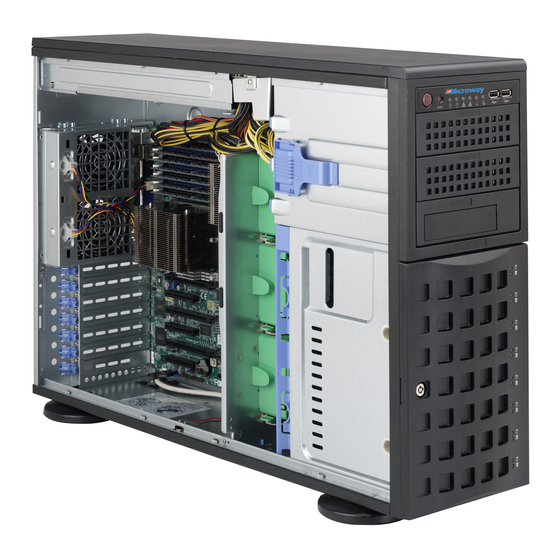
Chapter 1 Introduction Overview Supermicro’s SC745 4U chassis features a unique and highly-optimized design. The chassis is equipped with high efficiency power supply. High-performance fans provide ample optimized cooling for FB-DIMM memory modules and eight hot-swappable drive bays offer maximum storage capacity in a 4U form factor. -
Page 10: Chassis Features
SC745 Chassis Manual Chassis Features The SC745 4U high-performance chassis includes the following features: The SC745 chassis supports a DP/UP (dual processor/single processor). Please refer to the motherboard specifications pages on our Web site for updates on sup- ported processors. Hard Drives The SC745 chassis features eight slots for U320 SCSI or SAS/SATA drives. -
Page 11: Contacting Supermicro
Super Micro Computer, Inc. 980 Rock Ave. San Jose, CA 95131 U.S.A. Tel: +1 (408) 503-8000 Fax: +1 (408) 503-8008 Email: marketing@supermicro.com (General Information) support@supermicro.com (Technical Support) Web Site: www.supermicro.com Europe Address: Super Micro Computer B.V. Het Sterrenbeeld 28, 5215 ML... - Page 12 SC745 Chassis Manual Notes...
-
Page 13: Chapter 2 System Safety
Chapter 2: System Safety Chapter 2 System Safety Overview This chapter provides a quick setup checklist to get your chassis up and running. Following the steps in the order given should enable you to have your chassis set up and operational within a minimal amount of time. This quick setup assumes that you are an experienced technician, familiar with common concepts and terminology. -
Page 14: Electrical Safety Precautions
SC745 Chassis Manual Electrical Safety Precautions Basic electrical safety precautions should be followed to protect yourself from harm and the SC745 from damage: • Be aware of the locations of the power on/off switch on the chassis as well as the room’s emergency power-off switch, disconnection switch or electrical outlet. -
Page 15: General Safety Precautions
Chapter 2: System Safety • Handle used batteries carefully. Do not damage the battery in any way, a dam- aged battery may release hazardous materials into the environment. Do not discard a used battery in the garbage or a public landfill. Please comply with the regulations set up by your local hazardous waste management agency to dispose of your used battery properly. - Page 16 SC745 Chassis Manual • Use a grounded wrist strap designed to prevent electrostatic discharge. • Keep all components and printed circuit boards (PCBs) in their antistatic bags until ready for use. • Touch a grounded metal object before removing any board from its antistatic bag.
-
Page 17: Chapter 3 Chassis Components
Up to three GPUs • Seven expansion slots For the latest shipping lists, visit our Web site at: http://www.supermicro.com. This chassis accepts three hot-swappable system cooling fans and one (sometimes two) power supplies. SC745 models come in beige and black. -
Page 18: Fans
Supermicro Authorized Distributors / System Integrators / Resellers. A list of Supermicro Authorized Distributors / System Integrators /Reseller can be found at: http://www.supermicro.com. Click the Where... -
Page 19: Chapter 4 System Interface
Chapter 4: System Interface Chapter 4 System Interface Overview There are several LEDs on the control panel as well as others on the drive carriers to keep you constantly informed of the overall status of the system, as well as the activity and health of specific components. -
Page 20: Control Panel Buttons
Chassis Manual Control Panel Buttons There are two push-buttons located on the front of the chassis. These are the power on/off button and the reset button. • Power: The main power switch is used to apply or remove power from the power supply to the server system. - Page 21 Chapter 4: System Interface • NIC2: Indicates network activity on GLAN2 when flashing. • NIC1: Indicates network activity on GLAN1 when flashing. • HDD: Indicates IDE channel activity. SAS/SATA drive, SCSI drive, and/or DVD- ROM drive activity when flashing. • Power: Indicates power is being supplied to the system's power supply units.
-
Page 22: Drive Carrier Leds
Chassis Manual Drive Carrier LEDs Your chassis uses SAS/SATA or SCSI drives, but not both. SAS/SATA Drives Each SAS/SATA drive carrier has two LEDs. • Green: Each SAS/SATA drive carrier has a green LED. When illuminated, this green LED (on the front of the SAS/SATA drive carrier) indicates drive activity. A connection to the SATA backplane enables this LED to blink on and off when that particular drive is being accessed. -
Page 23: Chapter 5 Chassis Setup And Maintenance
Chapter 5: Chassis Setup and Maintenance Chapter 5 Chassis Setup and Maintenance Overview This chapter covers the steps required to install components and perform mainte- nance on the chassis. The only tool you will need to install components and perform maintenance is a Phillips screwdriver. -
Page 24: Removing The Chassis Front And Side Covers
SC745 Chassis Manual Removing the Chassis Front and Side Covers Side Cover Cover Latch Button Cover Latch Handle Figure 5-1: Removing the Chassis Cover The Side Cover Removing the Chassis Side Cover Push the cover latch button to release the latch handle. Pull the cover off the chassis using the latch handle. -
Page 25: The Front Cover
Chapter 5: Chassis Setup and Maintenance Front Cover Front Cover Lock Figure 5-2: Opening the Front Cover The Front Cover The front cover houses up to eight hot-swappable hard drives. The cover can be locked to prevent unauthorized access. The key to this lock is shipped with the system. -
Page 26: Configuring The Storage Module
SC745 Chassis Manual Configuring the Storage Module Storage Module Figure 5-3: Chassis in Tower Mode Storage Module Figure 5-4: Chassis in Rack Mount Mode Tower or Rack Configuration The SC745 chassis is shipped in tower mode and can be immediately used as desktop server. - Page 27 Chapter 5: Chassis Setup and Maintenance Storage Module Storage Module Release Lever Figure 5-5: Remove the Storage Module Rotating the Storage Module for Rack Mounting Open the chassis cover. Locate the storage module and disconnect any cables from the storage mod- ule to any component in the chassis.
-
Page 28: Adding Drives To The Storage Module
B. Add up to three peripheral drives (CD-ROM, DVD-ROM, etc.) drive trays. C. Add five hot swappable hard drives to the storage module. This configuration requires a mobile rack. More information on mobile racks can be found at the Supermicro Web site at www.supermicro.com... - Page 29 Chapter 5: Chassis Setup and Maintenance Drive Tray Release Tabs Figure 5-7: Remove Drive Tray Adding up to Three Peripheral/Hard Drives to the Drive Trays Open the chassis cover. Locate the drive tray release tab for the slot you want to place the peripheral drive.
- Page 30 SC745 Chassis Manual Hard Drive Tray Hard Drive Figure 5-8: Add a Hard Drive to the Drive Tray Place the hard drive into the hard drive tray. Make sure the type of hard drive (SAS/SATA or SCSI) is supported by the motherboard. The hard drive may not completely fill the tray.
- Page 31 Chapter 5: Chassis Setup and Maintenance Drive Tray Release Tabs Figure 5-9: Remove Drive Tray Up to three peripheral drives (DVD-ROM, CD-ROM and others) may be added to the drive trays. Adding up to Three Peripheral Drives to the Drive Trays Open the chassis cover.
- Page 32 SC745 Chassis Manual Hard Drive Tray Hard Drive Rails Figure 5-10: Add Hard Drive Rails to the DVD-ROM Drive Remove the hard drive tray rails from the hard drive tray. To do this, you must remove two screws from each side. Attach the rails to a DVD-ROM, CD-ROM or other peripherals.
- Page 33 The SC745 chassis accepts an M35TQ or M35S (SCSI) mobile rack to install extra hot-swappable hard drives. The mobile rack goes into the storage module which goes into the chassis. For more information on mobile racks, visit the Supermicro Web site at www. supermicro.com. Adding Five Hard Drives Using A Supermicro Mobile Rack Open the chassis cover.
- Page 34 SC745 Chassis Manual Hard Drive Rails Hard Drive Tray Figure 5-12: Remove the Hard Drive Rails Remove the hard drive tray rails from the hard drive tray. To do this, you must remove two screws from each side. Do this for all three hard drive trays. Attach the rails to a DVD-ROM, CD-ROM or other peripheral.
-
Page 35: Installing Hard Drives
Chapter 5: Chassis Setup and Maintenance Installing Hard Drives Drive Tray Handle Release Button Figure 5-14: Install Hard Drives The drives are mounted in drive carriers to simplify their installation and removal from the chassis. These carriers also help promote proper airflow for the drive bays. - Page 36 SC745 Chassis Manual Drive Tray SAS/SATA or SCSI Hard Drive Figure 5-15: Remove Dummy Drive Tray Remove the screws holding the drive tray to the dummy drive. Place a hard drive in the drive tray. Figure 5-16: Install Hard Drive Secure the hard drive to the tray using four screws.
-
Page 37: Installing The Motherboard
Chapter 5: Chassis Setup and Maintenance Installing the Motherboard I/O Shield The I/O shield holds the motherboard ports in place. Install the I/O shield before you install the motherboard. I/O Shield Figure 5-17: SC745 Chassis I/O Shield Installing the I/O Shield: Review the documentation that came with your motherboard. -
Page 38: Permanent And Optional Standoffs
SC745 Chassis Manual Permanent and Optional Standoffs Standoffs prevent short circuits by securing space between the motherboard and the chassis surface. The SC745 chassis packaging includes optional standoffs (hexagonal-shaped posts). These standoffs accept the rounded Phillips head screws which are also included in the SC745 accessories package. Standoffs Figure 5-18: Chassis Standoffs 5-16... -
Page 39: Installing The Motherboard
Chapter 5: Chassis Setup and Maintenance Installing the Motherboard Motherboard Installation Review the documentation that came with your motherboard. Become familiar with component placement, requirements, and precautions. Disconnect the power supply and lay the chassis on a flat surface. Open the chassis cover. As required by your motherboard, install standoffs in any areas that do not have a permanent standoff. -
Page 40: Power Supply Connections
SC745 Chassis Manual Power Supply Connections Connect each of the following cables as required by your motherboard manufacturer. In some instances not all of these cables are required, and some cables may not be included with the motherboard. Power Supply Cable Name Connects to Description... -
Page 41: Expansion Card And Pci Slot Setup
Chapter 5: Chassis Setup and Maintenance Lift the Press the Middle Release Tab of the Release Tab Figure 5-19: Add-on Card/Expansion Card Port Expansion Card and PCI Slot Setup After the motherboard has been installed, expansion cards may be installed. Installing Expansion Cards Locate the release tab on the top of the PCI slot bracket. - Page 42 SC745 Chassis Manual Figure 5-20: Remove PCI Card Slot Guard Remove the screw holding the bracket in place and pull the bracket from the chassis. Install your PCI card or other add-on card into the PCI slot bracket and moth- erboard.
-
Page 43: Installing The Air Shroud
Chapter 5: Chassis Setup and Maintenance Installing the Air Shroud Removable Tabs Figure 5-21: Air Shroud Air shrouds concentrate airflow to maximize fan efficiency. The SC745 chassis air shroud does not require screws to set up. NOTE: The air shroud includes tabs that can be removed if motherboard compo- nents prevent the air shroud from fitting securely. -
Page 44: Installation Complete
SC745 Chassis Manual Air Shroud Figure 5-22: Air Shroud in Place Checking the Airflow Make sure there are no objects to obstruct airflow in and out of the server. In addition, if you are using a front bezel, make sure the bezel's filter is replaced periodically. -
Page 45: System Fans
Chapter 5: Chassis Setup and Maintenance System Fans Five heavy-duty fans provide cooling for the chassis. Three fans are located in the front of the chassis with two fans in the rear. These fans circulate air through the chassis as a means of lowering the internal temperature of the chassis. The fans come pre-installed to the chassis. - Page 46 SC745 Chassis Manual Rear Fan Release Tab Figure 5-24: Rear Chassis Fans Replacing a Rear Chassis Fan Press the rear fan release tab. Pull the fan from the chassis top first. Place the new fan in the chassis bottom first. Push the fan fully into the housing until the fan clicks into place.
-
Page 47: Power Supply
Chapter 5: Chassis Setup and Maintenance Power Supply Depending on your chassis model, the SC745 chassis has an 800, 920 or 1200 Watt power supply. "R" model chassis feature a second redundant power supply. This power supply is auto-switching capable. This enables it to automatically sense and operate at a 100v to 240v input voltage. - Page 48 SC745 Chassis Manual Notes 5-26...
-
Page 49: Chapter 6 Rack Installation
Chapter 6: Rack Installation Chapter 6 Rack Installation Overview This chapter provides a quick setup checklist to get your chassis up and running. Following these steps in the order given should enable you to have the system operational within a minimum amount of time. Unpacking the System You should inspect the box the chassis was shipped in and note if it was damaged in any way. -
Page 50: Rack Precautions
SC745 Chassis Manual Warnings and Precautions! Rack Precautions • Ensure that the leveling jacks on the bottom of the rack are fully extended to the floor with the full weight of the rack resting on them. • In single rack installation, stabilizers should be attached to the rack. •... -
Page 51: Rack Mounting Considerations
Chapter 6: Rack Installation Rack Mounting Considerations Ambient Operating Temperature If installed in a closed or multi-unit rack assembly, the ambient operating tempera- ture of the rack environment may be greater than the ambient temperature of the room. Therefore, consideration should be given to installing the equipment in an environment compatible with the manufacturer’s maximum rated ambient tempera- ture (Tmra). -
Page 52: Rack Mounting Instructions
SC745 Chassis Manual Rack Mounting Instructions This section provides information on installing the SC745 chassis into a rack unit with the rails provided. There are a variety of rack units on the market, which may mean the assembly procedure will differ slightly. You should also refer to the instal- lation instructions that came with the rack unit you are using. - Page 53 Chapter 6: Rack Installation Removing the Top Cover Locate the chassis cover lock (blue lever) at the rear of the chassis cover. Slide the chassis cover lock to the right and push chassis cover forward. Lift the chassis top cover off the chassis. Removing the Chassis Feet Place the chassis on its side with the chassis side cover facing upward.
-
Page 54: Identifying The Sections Of The Rack Rails
SC745 Chassis Manual Identifying the Sections of the Rack Rails The chassis package includes two rack rail assemblies in the rack mounting kit. Each assembly consists of two sections: an inner fixed chassis rail that secures directly to the server chassis and an outer fixed rack rail that secures directly to the rack itself. - Page 55 Chapter 6: Rack Installation Figure 6-3: Installing the Inner Rack Rails Installing the Chassis Handles and Inner Rails Locate the two chassis handles and six handle screws. Align the chassis handle with the front of the chassis and secure with the three chassis handle screws.
- Page 56 SC745 Chassis Manual Secure to the Rear of the Rack Attach to Middle Section Secure to the Front of the Rack Figure 6-4: Assembling the Outer Rails Installing the Outer Rails onto the Rack Attach the front and rear short brackets to the outside of the long bracket. Both bracket ends must face the same direction.
- Page 57 Chapter 6: Rack Installation Figure 6-5: Installing the Chassis into a Rack Installing the Chassis into a Rack Confirm that chassis includes the inner rails and the outer rails. Fro m Subject Siz e Rec eived Line chassis rails with the front of the rack rails. Ro d Coleman Ray mond Miller RE: SC825 C hass Slide the chassis rails into the rack rails, keeping the pressure even on both...
-
Page 58: Tower Mounting Instructions
SC745 Chassis Manual Tower Mounting Instructions The SC745 chassis is shipped with the chassis cover and feet pre-installed. To use the chassis as a desktop server, no other installation is required. Use the instructions in this section if you have converted the chassis for rack use and need to return the chassis to tower mounting. - Page 59 Chapter 6: Rack Installation Chassis Foot Receptacle Chassis Foot Chassis Screw Figure 6-7: Placing Chassis Feet Placing the Chassis Feet Place the chassis foot in the foot receptacle and slide the foot toward the front of the chassis. The foot should lock into place. Secure the foot to the chassis using one screw enclosed in the packaging.
- Page 60 SC745 Chassis Manual Notes 6-12...
- Page 61 This appendix lists supported cables for your chassis system. It only includes the most commonly used components and configurations. For more compatible cables, refer to the manufacturer of the motherboard you are using and our Web site at: www.supermicro.com. A-2 Cables Included with SC745TQ Chassis (SAS/SATA) SC745TQ-R800/800...
- Page 62 SC745 Chassis Manual A-4 Compatible Cables The following cables are compatible with the SC745 chassis. Some compatible motherboards have different connectors. If your motherboard has only one SAS connector that the SAS/SATA cables must share, use one of the following cables. These cables must be purchased separately. Cable Name: SAS Cable Quantity: 1 Part #: CBL-0175L...
-
Page 63: Extending Power Cables
Appendix A: Chassis Cables Extending Power Cables Although Supermicro chassis are designed with to be efficient and cost-effective, some compatible motherboards have power connectors located in different areas. To use these motherboards you may have to extend the power cables to the mother boards. - Page 64 SC745 Chassis Manual Notes...
- Page 65 Appendix B: Power Supply Specifications Appendix B SC745 Power Supply Specifications This appendix lists power supply specifications for your chassis system. 800W (Redundant = X2) MFR Part # PWS-801-1R 100 - 240V Rated AC Voltage 50 - 60Hz 10 - 4 Amp +5V standby 4 Amp +12V...
- Page 66 SC745 Chassis Manual 1200W (Redundant = X2) MFR Part # PWS-1K21P-1R 100 - 140V, 50 - 60Hz, 8 - 11.5 Amp Rated AC Voltage 180 - 240V, 50 - 60Hz, 5.5 - 8 Amp 1000W, 83 Amp @ 100-140V DC Output +12V 1200W, 100 Amp @ 180-240V 5Vsb: 4A +5V: 50 Amp...
- Page 67 Appendix C: SAS-743TQ Backplane Specifications Appendix C SAS-743TQ Backplane Specifications To avoid personal injury and property damage, carefully follow all the safety steps listed below when accessing your system or handling the components. C-1 ESD Safety Guidelines Electrostatic Discharge (ESD) can damage electronic com ponents. To prevent dam- age to your system, it is important to handle it very carefully.
- Page 68 This manual reflects SAS-743TQ Revision 3.00, the most current release available at the time of publication. Always refer to the Supermicro Web site at www.supermi- cro.com for the latest updates, compatible parts and supported configurations.
- Page 69 Appendix C: SAS-743TQ Backplane Specifications C-5 Front Connectors, Jumpers and LEDs M 8 7 M 9 6 M 8 6 M 9 7 UPER SAS743TQ M M 3 M M 2 REV 3.00 +12V +12V GND +5V Figure C-1: Front Connectors JTAG Connector: JP47 C Connector #1 JP44 Upgrade Connector: JP46...
- Page 70 SC745 Chassis Manual C-6 Front Connector and Pin Definitions #1. and 2. JTAG Connector and Upgrade Connectors The JTAG and Upgrade connectors, des- ignated JP47 and JP46, are used for diag- nostic purposes. These connectors should be used by a certified and experienced technician.
- Page 71 Appendix C: SAS-743TQ Backplane Specifications #6. and #7. Sideband Headers Sideband Headers The sideband headers are designated JP51 Pin # Definition Pin # Definition and JP52. For SES-2 to work properly, you Backplane Controller must connect an 10-pin sideband cable. Addressing ID (SB6) (SB5)
- Page 72 SC745 Chassis Manual C-7 Front Jumper Locations and Pin Definitions M 8 7 M 8 6 M 9 7 M 9 6 UPER SAS743TQ REV 3.00 M 8 6 M 9 7 JP50 JP38 REV 3.00 JP40 JP41 JP33 JP34 JP36 JP37 JP29...
-
Page 73: Explanation Of Jumpers
Appendix C: SAS-743TQ Backplane Specifications Explanation of Jumpers Connector To modify the operation of the backplane, Pins jumpers can be used to choose between optional settings. Jumpers create shorts between two pins to change the function Jumper of the connector. Pin 1 is identified with a square solder pad on the printed circuit board. - Page 74 SC745 Chassis Manual C and SGPIO Mode Jumper Settings This backplane can utilize I C or SGPIO. I C is the default mode and can be used without making changes to your jumpers. The following information details which jumpers must be configured to use SGPIO mode or restore your backplane to I mode.
-
Page 75: Front Led Indicators
Appendix C: SAS-743TQ Backplane Specifications Front LED Indicators M 8 7 M 9 6 M 8 6 M 9 7 UPER SAS743TQ M M 3 M M 2 REV 3.00 OH/Drive Fail LED +12V +12V GND +5V Figure C-3: Front LEDs Front Panel LEDs State Specification... - Page 76 SC745 Chassis Manual C-8 Rear Connectors and LED Indicators SAS #0 SAS #1 SAS #2 SAS #3 SAS #4 SAS #5 SAS #6 SAS #7 Figure C-4: Rear Connectors Rear SAS/SATA Connectors Rear Connector SAS Drive Number SAS #0 SAS/SATA HHD #0 SAS #1 SAS/SATA HHD #1 SAS #2...
- Page 77 Appendix C: SAS-743TQ Backplane Specifications Notes C-11...
- Page 78 SC745 Chassis Manual Disclaimer (cont.) The products sold by Supermicro are not intended for and will not be used in life sup- port systems, medical equipment, nuclear facilities or systems, aircraft, aircraft devices, aircraft/emergency communication devices or other critical systems whose failure to per- form be reasonably expected to result in significant injury or loss of life or catastrophic property damage.