
Related Manuals for Supero SC748S-R1000B


Summary of Contents for Supero SC748S-R1000B
- Page 1 UPER ® SC748 Chassis Series SC748TQ-R1000(B) SC748TQ-R1200(B) SC748S-R1000(B) USER’S MANUAL...
- Page 2 Please Note: For the most up-to-date version of this manual, please see our web site at www.supermicro.com. Super Micro Computer, Inc. ("Supermicro") reserves the right to make changes to the product described in this manual at any time and without notice. This product, including software, if any, and documentation may not, in whole or in part, be copied, photocopied, reproduced, translated or reduced to any medium or machine without prior written consent.
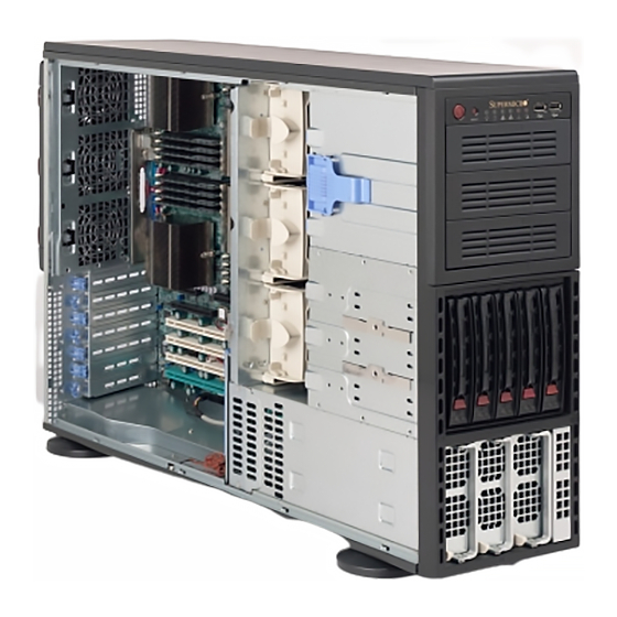
- Page 3 SC748 4U chassis. Installa- tion and maintenance should be performed by experienced technicians only. Supermicro’s SC748 4U chassis features a unique and highly-optimized design for dual-core Xeon platforms. The chassis is equipped with a redundant 1000 or 12000 Watt high-efficiency power supply for superb power savings.
-
Page 4: Manual Organization
SC748 Chassis Manual Manual Organization Chapter 1: Introduction The first chapter provides a checklist of the main components included with this chassis and describes the main features of the SC748 chassis. This chapter also includes contact information. Chapter 2: System Safety This chapter lists warnings, precautions, and system safety. - Page 5 Preface Compatible Backplanes This section lists compatible cables, power supply specifications, and compatible backplanes. Not all compatible backplanes are listed. Refer to our Web site for the latest compatible backplane information. Appendix A: Chassis Cables Appendix B: Power Supply Specifications Appendix C: MT35TQ Mobile Rack Specifications Appendix D: MT35S and MT35T Mobile Rack Specifications...
-
Page 6: Table Of Contents
Hard Drives ......................2 Mobile Rack ....................... 2 I/O Expansion slots .................... 2 Peripheral Drives ....................2 Other Features ....................2 Contacting Supermicro ..................3 Returning Merchandise for Service..............4 Chapter 2 System Safety Overview ......................1 Warnings and Precautions ................. 1 Preparing for Setup .................... - Page 7 Configuring the Storage Module ............... 3 Tower or Rack Configuration................3 Adding Drives to the Storage Module ..............5 Adding Five Hard Drives to a Supermicro Mobile Rack: ......... 10 Installing Hard Drives ..................12 Installing Hard Drives in the Chassis ............... 12 Installing the Motherboard ................
- Page 8 SC748 Chassis Manual Rack Mounting Instructions ................4 Removing the Chassis Cover and Feet ............. 4 Identifying the Sections of the Rack Rails ............6 Tower Mounting Instructions ................11 Appendix A SC748 Chassis Cables Appendix B SC748 Power Supply Specifications Appendix C CSE-M35TQ Mobile Rack Specifications Appendix DCSE-M35S/CSE-M35T1 Backplane Specifications viii...
-
Page 9: Chapter 1: Introduction
Chapter 1 Introduction Overview Supermicro’s SC748 4U chassis features a unique and highly-optimized design. The chassis is equipped with high efficiency power supply. High performance fans pro- vide ample optimized cooling for FB-DIMM memory modules, 5 hot-swap drive bays and 3 peripheral drive bays offer maximum storage capacity in a 4U form factor. -
Page 10: Chassis Features
SC748 Chassis Manual Chassis Features The SC748 4U high-performance chassis includes the following features: The SC748 Chassis supports a DP Dual-core Xeon processor. Please refer to the motherboard specifications pages on our web site for updates on supported processors. Hard Drives The SC748 Chassis features five slots for U320 SCSI or SAS/SATA drives. -
Page 11: Contacting Supermicro
Super Micro Computer, Inc. 980 Rock Ave. San Jose, CA 95131 U.S.A. Tel: +1 (408) 503-8000 Fax: +1 (408) 503-8008 Email: marketing@supermicro.com (General Information) support@supermicro.com (Technical Support) Web Site: www.supermicro.com Europe Address: Super Micro Computer B.V. Het Sterrenbeeld 28, 5215 ML... -
Page 12: Returning Merchandise For Service
For faster service, RMA authorizations may be requested online (http://www. supermicro.com/support/rma/). Whenever possible, repack the chassis in the original Supermicro carton, using the original packaging material. If these are no longer available, be sure to pack the chassis securely, using packaging material to surround the chassis so that it does not shift within the carton and become damaged during shipping. -
Page 13: Chapter 2 System Safety
Chapter 2: System Safety Chapter 2 System Safety Overview This chapter provides a quick setup checklist to get your chassis up and running. Following the steps in order given should enable you to have your chassis setup and operational within a minimal amount of time. This quick set up assumes that you are an experienced technician, familiar with common concepts and terminology. -
Page 14: Electrical Safety Precautions
SC748 Chassis Manual Electrical Safety Precautions Basic electrical safety precautions should be followed to protect yourself from harm and the SC748 from damage: • Be aware of the locations of the power on/off switch on the chassis as well as the room’s emergency power-off switch, disconnection switch or electrical outlet. -
Page 15: General Safety Precautions
Chapter 2: System Safety radiation exposure, do not open the enclosure or use the unit in any uncon- ventional way. General Safety Precautions • Keep the area around the chassis clean and free of clutter. • Place the chassis top cover and any system components that have been re- moved away from the system or on a table so that they won’t accidentally be stepped on. - Page 16 SC748 Chassis Manual • Do not let components or PCBs come into contact with your clothing, which may retain a charge even if you are wearing a wrist strap. • Handle a board by its edges only; do not touch its components, peripheral chips, memory modules or contacts.
-
Page 17: Chapter 3 Chassis Components
• Three 5.25" peripheral drive bays • Seven add-on/expansion card slots. For the latest shipping lists, visit our Web site at: http://www.supermicro.com. This chassis accepts three hot-swappable system cooling fans and two power SC748 chassis supplies. come in beige or black. Drive bays may be used for up to three 5.25"... -
Page 18: Fans
Supermicro Authorized Distributors / System Integrators / Resellers. A list of Supermicro Authorized Distributors / System Integrators /Reseller can be found at: http://www.supermicro.com. Click the Where... -
Page 19: Chapter 4 System Interface
Chapter 4: System Interface Chapter 4 System Interface Overview There are several LEDs on the control panel as well as others on the drive carriers to keep you constantly informed of the overall status of the system as well as the activity and health of specific components. -
Page 20: Control Panel Buttons
SC748 Chassis Manual Control Panel Buttons There are two push-buttons located on the front of the chassis. These are power on/off button and a reset button. • Power: The main power switch is used to apply or remove power from the power supply to the server system. -
Page 21: Drive Carrier Leds
Chapter 4: System Interface • HDD: Indicates IDE channel activity. SAS/SATA drive, SCSI drive, and/or DVD- ROM drive activity when flashing. • NIC2: Indicates network activity on GLAN2 when flashing. • NIC1: Indicates network activity on GLAN1 when flashing. • Power Fail: Indicates a power failure to the system's power supply units. -
Page 22: Scsi Drives
SC748 Chassis Manual SCSI Drives Each SCSI drive carrier has two LEDs. • Green: When illuminated, the green LED on the front of the SCSI drive carrier indicates drive activity. A connection to the SCSI SCA backplane enables this LED to blink on and off when that particular drive is being accessed. •... -
Page 23: Chapter 5 Chassis Setup And Maintenance
Chapter 5: Chassis Setup and Maintenance Chapter 5 Chassis Setup and Maintenance Overview This chapter covers the steps required to install components and perform mainte- nance on the chassis. The only tool you will need to install components and perform maintenance is a Phillips screwdriver. -
Page 24: Removing The Chassis Cover
SC748 Chassis Manual Removing the Chassis Cover Remove Screws Figure 5-1: Removing the Chassis Cover Removing the Chassis Cover Unplug the chassis from any power source Remove the two screws securing the cover to the chassis. Press the release tabs simultaneously. Slide the cover forward. -
Page 25: Configuring The Storage Module
Chapter 5: Chassis Setup and Maintenance Configuring the Storage Module Storage Module Figure 5-2: Chassis in Tower Mode Storage Module Figure 5-3: Chassis in Rack Mount Mode Tower or Rack Configuration The SC748 chassis is shipped in tower mode and can be immediately used as desktop server. - Page 26 SC748 Chassis Manual Storage Module Storage Module Release Lever Figure 5-4: Remove the Storage Module Rotating the Storage Module for Rack Mounting Open the chassis cover. Locate the storage module and disconnect any cables from the storage mod- ule to any component in the chassis. Push the storage module release lever.
-
Page 27: Adding Drives To The Storage Module
Chapter 5: Chassis Setup and Maintenance Figure 5-5: Chassis Storage Module Adding Drives to the Storage Module The storage module includes three full sized drive bays and the front LED panel. The storage module can be set up in a variety of configurations: There are three basic configurations (see A, B, and C below) which can then be combined within the three bays to suit the user's needs. - Page 28 SC748 Chassis Manual Drive Tray Release Tabs Figure 5-6: Remove Drive Tray Installing Hard Drives into the Drive Trays Open the chassis cover. Locate the drive tray release tab for the slot you want to place the peripheral drive. Push the drive tray toward the front of the chassis.
- Page 29 Chapter 5: Chassis Setup and Maintenance Hard Drive Tray Hard Drive Figure 5-7: Add a Hard Drive to the Drive Tray Place the hard drive to the hard drive tray. Make sure The hard drive can be SAS or SCSI depending on your motherboard. The hard drive may not completely fill the tray.
- Page 30 SC748 Chassis Manual Drive Tray Release Tab Figure 5-8: Remove Drive Tray Adding Peripheral Drives (DVD-ROM, CD-ROM, Floppy Drive, etc.) to the Drive Trays Open the chassis cover. Locate the drive tray release tab for the slot you want to place the peripheral drive.
- Page 31 Chapter 5: Chassis Setup and Maintenance Hard Drive Tray Hard Drive Rails Figure 5-9: Add Hard Drive Rails to the DVD-ROM Drive Remove the hard drive tray rails from the hard drive tray. To do this, you must remove two screws from each side. Attach the rails to a DVD-ROM, CD-ROM, floppy drive, or other peripheral.
-
Page 32: Adding Five Hard Drives To A Supermicro Mobile Rack
Drive Tray Release Tabs Figure 5-10: Removing the Drive Bay Adding Five Hard Drives to a Supermicro Mobile Rack: The SC748 chassis accepts a CSE-M35S (SCSI) or CSE-M35T-1/CSE-M35TQ (SAS/SATA) mobile rack in order to install hot swappable hard drives. The mobile rack replaces the storage module in the chassis. - Page 33 Chapter 5: Chassis Setup and Maintenance Storage Module Figure 5-11: The Storage Module Install all six storage module rails onto the mobile rack. Each rail requires two screws. Make sure the arrow on the rail points toward the front of the chassis. Slide the mobile rack into the chassis.
-
Page 34: Installing Hard Drives
SC748 Chassis Manual Installing Hard Drives Release Button Drive Tray Handle Figure 5-13: Install Hard Drives Installing Hard Drives in the Chassis The drives are mounted in drive carriers to simplify their installation and removal from the chassis. These carriers also help promote proper airflow for the drive bays. - Page 35 Chapter 5: Chassis Setup and Maintenance Drive Tray SAS/SATA or SCSI Hard Drive Figure 5-14: Removing the Dummy Drive Tray Remove the screws holding the drive tray to the dummy drive. Place a hard drive in the drive tray. Figure 5-15: Installing the Hard Drive Secure the hard drive to the tray using four screws.
-
Page 36: Installing The Motherboard
SC748 Chassis Manual Installing the Motherboard I/O Slot Shield The I/O shield holds the motherboard ports in place. Install the I/O shield before you install the motherboard. I/O Shield Figure 5-16: SC748 Chassis I/O Shield Installing the I/O Shield Review the documentation that came with your motherboard. Become familiar with component placement, requirements, and precautions. -
Page 37: Permanent And Optional Standoffs
Chapter 5: Chassis Setup and Maintenance Permanent and Optional Standoffs Standoffs prevent short circuits by securing space between the motherboard and the chassis surface. The SC748 chassis packaging includes optional standoffs (hexagon shaped posts). These standoffs accept the rounded Phillips head screws included in the SC748 accessories packaging. -
Page 38: Motherboard Installation
SC748 Chassis Manual Motherboard Installation Installing the Motherboard: Review the documentation that came with your motherboard. Become familiar with component placement, requirements, and precautions. Disconnect the power supply and lay the chassis on a flat surface. Open the chassis cover. As required by your motherboard, install standoffs in any areas that do not have a permanent standoff. -
Page 39: Power Supply Connections
Attach the Hard drive power hard drive connectors to the backplane. If Backplane cable you are using a Supermicro back- plane, the floppy drive connector does not need to be attached. Provides power to the motherboard CPU. 8-pin mother-... -
Page 40: Add-On Card/Expansion Slot Setup
SC748 Chassis Manual Lift the Press the Middle Release Tab of the Release Tab Figure 5-19: Add-on Card/Expansion Card Port Add-on Card/Expansion Slot Setup After motherboard installation, install add-on cards to the chassis, such as PCI cards. Installing Add-on and Expansion Cards Locate the release tab on the top of the PCI bracket. - Page 41 Chapter 5: Chassis Setup and Maintenance Figure 5-20: Remove PCI Card Slot Guard Remove the screw holding the bracket in place and pull the bracket from the chassis. Install your PCI card or other add-on card into the PCI slot bracket and moth- erboard.
-
Page 42: Installing The Air Shroud
SC748 Chassis Manual Installing the Air Shroud Figure 5-21B: AMD Figure 5-21A: Intel CPU Air Shroud CPU Air Shroud Air shrouds concentrate airflow to maximize fan efficiency. The SC748 chassis air shroud does not require screws to set it up. The SC748 chassis supports two different air shroud designs, one for AMD CPUs and, and another for Intel CPUs. -
Page 43: Checking The Server's Air Flow
Chapter 5: Chassis Setup and Maintenance Air Shroud Figure 5-22: Air Shroud in Place Checking the Server's Air Flow Check the Following Make sure there are no objects obstructing the airflow in and out of the server. In addition, if you are using a front bezel, make sure the bezel's filter is replaced periodically. -
Page 44: System Fans
SC748 Chassis Manual System Fans Five heavy duty fans provide cooling for the chassis. Three fans are located in the front of the chassis and two fans are in the rear. These fans circulate air through the chassis as a means of lowering the internal temperature of the chassis. The fans come pre-installed to the chassis. -
Page 45: Replacing A Rear Chassis Fan
Chapter 5: Chassis Setup and Maintenance Rear Fan Release Tab Figure 5-24: Rear Chassis Fans Replacing a Rear Chassis Fan Rear Fan Replacement Procedure Press the rear fan release tab. Pull the fan from the chassis top first. Place the new fan in the chassis bottom first. Push the fan fully into the housing until the fan clicks into place. -
Page 46: Power Supply
SC748 Chassis Manual Power Supply Depending on your chassis model, the SC748 Chassis has a 1000W or 1200W (re- dundant) power supply. This power supply is auto-switching capable. This enables it to automatically sense and operate at a 100v to 240v input voltage. An amber light will be illuminated on the power supply when the power is off. - Page 47 Chapter 5: Chassis Setup and Maintenance Pull the Drive Out Using the Handle Press the Release Button Figure 5-25: Removing a Power Supply 5-25...
-
Page 48: Chapter 6 Rack Installation
Chapter 6: Rack Installation Chapter 6 Rack Installation Overview This chapter provides a quick setup checklist to get your chassis up and running. Following these steps in the order given should enable you to have the system operational within a minimum amount of time. Unpacking the System You should inspect the box the chassis was shipped in and note if it was damaged in any way. -
Page 49: Rack Precautions
SC748 Chassis Manual Warnings and Precautions! Rack Precautions • Ensure that the leveling jacks on the bottom of the rack are fully extended to the floor with the full weight of the rack resting on them. • In single rack installation, stabilizers should be attached to the rack. •... -
Page 50: Rack Mounting Considerations
Chapter 6: Rack Installation • Always keep the rack's front door and all panels and components on the servers closed when not servicing to maintain proper cooling. Rack Mounting Considerations Ambient Operating Temperature If installed in a closed or multi-unit rack assembly, the ambient operating tempera- ture of the rack environment may be greater than the ambient temperature of the room. -
Page 51: Rack Mounting Instructions
SC748 Chassis Manual Rack Mounting Instructions This section provides information on installing the SC748 chassis into a rack unit with the rails provided. There are a variety of rack units on the market, which may mean the assembly procedure will differ slightly. You should also refer to the installation instructions that came with the rack unit you are using. - Page 52 Chapter 6: Rack Installation Removing the Chassis Top Cover Locate the chassis cover lock (blue lever) at the rear of the chassis cover. Slide the chassis cover lock to the right and push chassis cover forward. Lift the chassis top cover off the chassis. Removing the Chassis Feet Place the chassis on its side with the chassis side cover facing upward.
-
Page 53: Identifying The Sections Of The Rack Rails
SC748 Chassis Manual Identifying the Sections of the Rack Rails The chassis package includes two rack rail assemblies in the rack mounting kit. Each assembly consists of two sections: an inner fixed chassis rail that secures directly to the server chassis and an outer fixed rack rail that secures directly to the rack itself. - Page 54 Chapter 6: Rack Installation Figure 6-4: Installing the Inner Rack Rails Locate the inner rails (2) and screws (12) in the shipping package. Align the inner rails against the chassis, as shown. Confirm that the rails are flushed against the edge of the chassis. Tighten the screws.
- Page 55 SC748 Chassis Manual Secure to the Rear of the Rack Attach to Rear Bracket Secure to the Front of the Rack Figure 6-5: Assembling the Outer Rails Installing the Outer Rails to the Rack Attach the front and rear short brackets to the outside of the long bracket. Both bracket ends must face the same direction.
- Page 56 Chapter 6: Rack Installation Figure 6-6. Installing the Rack Rails Installing the Chassis into a Rack Confirm that chassis includes the inner rails and the outer rails. Line chassis rails with the front of the rack rails (C). Slide the chassis rails into the rack rails, keeping the pressure even on both sides (you may have to depress the locking tabs when inserting).
- Page 57 SC748 Chassis Manual Figure 6-7: Installing the Chassis into a Rack 6-10...
-
Page 58: Tower Configuration Instructions
Chapter 6: Rack Installation Tower Configuration Instructions The SC748 chassis is shipped with the chassis cover and feet pre-installed. To use the chassis as a desktop server, no other installation is required. Use the instructions in this section if you have converted the chassis for rack use and need to return the chassis to tower mounting. - Page 59 SC748 Chassis Manual Chassis Foot Receptacle Chassis Foot Chassis Screw Figure 6-9: Placing Chassis Feet Placing the Chassis Feet Place the chassis foot in the foot receptacle and slide the foot toward the front of the chassis. The foot should lock into place. Secure the foot to the chassis using one screw enclosed in the packaging.
-
Page 60: Appendix A Sc748 Chassis Cables
This appendix lists supported cables for your chassis system. It only includes the most commonly used components and configurations. For more compatible cables, refer to the manufacturer of the motherboard you are using and our Web site at: www.supermicro.com. A-2 Cables Included with SC748TQ Chassis (SAS/SATA) SC748TQ-R1200 and SC748TQ-R1000... - Page 61 SC748 Chassis Manual A-4 Compatible Cables These cables are compatible with the SC748 Chassis. This section lists cables included with the SC748 Chassis packages Alternate SAS/SATA Cables Some compatible motherboards have different connectors. If your motherboard has only one SAS connector that the SAS/SATA cables must share, use one of the following cables.
-
Page 62: Extending Power Cables
Appendix A: Chassis Cables Extending Power Cables Although Super Micro chassis are designed with to be efficient and cost-effective, some compatible motherboards have power connectors located in different areas. To use these motherboards you may have to extend the power cables to the mother boards. - Page 63 SC748 Chassis Manual Notes...
-
Page 64: Appendix B Sc748 Power Supply Specifications
Appendix B: Power Supply Specifications Appendix B SC748 Power Supply Specifications This appendix lists power supply specifications for your chassis system. PWS-1K01-1R 1000W (Redundant = X2) MFR Part # PWS-1K01-1R 100 - 240V Rated AC Voltage 50 - 60Hz 15 - 7 Amp +5V standby 4 Amp +12V 66 Amp +5V 20 Amp... - Page 65 SC748 Chassis Manual Notes...
-
Page 66: Appendix C Cse-M35Tq Mobile Rack Specifications
Appendix C: CSE-M35TQ Mobile Rack Specifications Appendix C CSE-M35TQ Mobile Rack Specifications To avoid personal injury and property damage, carefully follow all the safety steps listed below when accessing your system or handling the components. C-1 ESD Safety Guidelines Electric Static Discharge (ESD) can damage electronic com ponents. To prevent dam- age to your system, it is important to handle it very carefully. -
Page 67: Front Connectors
SC748 Chassis Manual C-4 Front Connectors and Jumpers Front Connectors 1. Power Connectors (4-pin): JP10 8. Upgrade JP46 and JP13 9. ACT IN JP26 2. Chip: MG 9072 10. FAN Connector JP22 3. JTAG JP47 11. SAS Port #0 J5 4. - Page 68 Appendix C: CSE-M35TQ Mobile Rack Specifications C-5 Front Connector and Pin Definitions 1. Mobile rack Main Power Connectors Mobile rack Main Power The 4-pin connectors, designated JP10 and 4-Pin Connector (JP10 and JP13) JP13, provide power to the mobile rack. See Pin# Definition the table on the right for pin definitions.
- Page 69 SC748 Chassis Manual 6 and 7. Sideband Headers Sideband Headers (JP51 and JP52) The sideband headers are designated JP51 Pin # Definition Pin # Definition and JP52. For SES-2 to work properly, you Mobile rack Controller must connect an 8-pin sideband cable. See the Addressing ID (SB6) (SB5)
-
Page 70: Explanation Of Jumpers
Appendix C: CSE-M35TQ Mobile Rack Specifications C-6 Front Jumper Locations and Pin Definitions JP62 JP38 JP29 JP50 JP36 JP40 JP41 JP33 JP37 JP43 JP61 JP34 JP42 JP18 Explanation of Jumpers To modify the operation of the mobile rack, Connector Pins jumpers can be used to choose between optional settings. -
Page 71: Jumper Settings
SC748 Chassis Manual Jumper Settings Jumper Jumper Settings Notes Open: Enabled Buzzer Reset JP18 Closed: Disabled Open: Default 9072 Chip Reset JP29 Closed: Reset Fan Jumper Settings This mobile rack can use up to four fans. To utilize each fan, you must configure both jumpers as instructed below. -
Page 72: I2C And Sgpio Modes And Jumper Settings
Appendix C: CSE-M35TQ Mobile Rack Specifications I2C and SGPIO Modes and Jumper Settings This mobile rack can utilize I2C or SGPIO. I2C is the default mode and can be used without making changes to your jumpers. The following information details which jumpers must be configured to use SGPIO mode or restore your mobile rack to I2C mode. -
Page 73: Sas Port Connections In I2C And Sgpio Settings
SC748 Chassis Manual SAS Port Connections in I2C and SGPIO Settings Use the following chart when connecting this mobile rack. If you connect the SAS ports out of order, you will not able to easily identify drives using the LED func- tion. - Page 74 Appendix C: CSE-M35TQ Mobile Rack Specifications C-7 Rear Connectors and LED Indicators SAS #0 FAIL #0 ACT #0 SAS #1 FAIL #1 ACT #1 SAS #2 FAIL #2 ACT #2 SAS #3 FAIL #3 ACT #3 SAS #4 FAIL #4 ACT #4 FAN FAIL OH / DRIVE FAIL Rear SAS/SATA Connectors...
- Page 75 SC748 Chassis Manual Rear LED Indicators Rear LED Hard Drive Activity Failure LED SAS #0 SAS #1 SAS #2 SAS #3 SAS #4 Mobile Rack Backplane LEDs Hard Drive Activity Failure LED Overheat/Drive Failure LED indicator (Red light: flashing, buzzer on) Overheat/Drive Failure LED indicator (Red light: flashing, buzzer on) C-10...
- Page 76 Appendix C: CSE-M35TQ Mobile Rack Specifications Installation Procedures C-8 Tools Needed The following tools are neeed for the installation of the mobile rack into the chas- sis: • Phillips head screwdriver • Antistatic Strap (recommended) C-9 Important Safety Guidelines This product should be assembled and/or serviced by qualified and experienced technicians.
- Page 77 SC748 Chassis Manual C-10 Connecting Cables to the Mobile Rack Before connecting cables the mobile rack, you must remove the exhaust fan. In some circumstances, the backplane may need to be removed. Figure C-5: Removing Mobile Rack Fan Connecting SAS/SATA and Power Cables to the Mobile Rack: Before connecting the mobile rack, you must remove exhaust fan.
- Page 78 Appendix C: CSE-M35TQ Mobile Rack Specifications Figure C-6: Removing Mobile Rack Fan Pull the exhaust fan from the chassis. C-13...
- Page 79 SC748 Chassis Manual Figure C-7: Removing Mobile Rack Fan Remove the bracket screw and pull the bracket from the mobile rack. Connect the SAS cables and power cables to the mobile rack backplane. Replace the bracket, bracket screw, and fan to the mobile rack. C-14...
- Page 80 Appendix C: CSE-M35TQ Mobile Rack Specifications Figure C-8: Removing Mobile Rack Fan Additional Installation Information The backplane may be separated from the mobile rack by removing the seven screws holding the backplane in place. C-15...
- Page 81 CSE-M35S/CSE-M35T1 Mobile Rack Specifications Appendix D CSE-M35S/CSE-M35T1 Mobile Rack Specifications Supermicro’s CSE-M35S/CSE-M35T1 mobile rack series offers the cutting edge technology with greater flexibility. The CSE-M35T1 supports five Serial ATA hot- swappable hard drives that yield a unparalleled storage capacity without compro- mising productivity by eliminating possible system downtime.
- Page 82 SC748 Chassis Manual D-2 Technical Specifications Occupancy Three (3) 5.25" Drive Bays Capacity Five (5) 1" SCA Ultra320/160 Hard Drives with SAF-TE built-in (*CSE-M35S only) Five (5) 1" Host Receptacle Connectors, SATA hot-swap hard drives (*CSE-M35T-1 only) Cooling One (1) 9cm Exhaust Fan Subsystem System Fan Fail Detection LED and Alarm...
- Page 83 CSE-M35S/CSE-M35T1 Mobile Rack Specifications D-3 Jumper Settings Jumper Settings for the CSE-M35S (SCSI): Jumper Description Setting JP18 Buzzer Reset Closed: Enable, Open: Disable (*Default) JP21 SCSI Termination Closed: Enable (*Default), Open: Disable JP24 SCSI ID Selection 1-2: SCSI Ids: 0,1,2,3,4 (*Default), 2-3: SCSI Ids: 9,10,11,12,13 JP29 GEM 318 IDs...
- Page 84 SC748 Chassis Manual Jumper Settings for the CSE-M35T1 (SATA): Location of Jumpers JP26 Figure D-2: Jumper Locations Activity LEDs- Pin Definitions Channel 1 Act. LED 1 Channel 2 Act. LED 2 Channel 3 Act. LED 3 Channel 4 Act. LED 4 Channel 5 Act.
- Page 85 CSE-M35S/CSE-M35T1 Mobile Rack Specifications D-4 Installation Procedures For the CSE-M35S: SCSI IDs are assigned automatically by the backplane. Do not set IDs man- ually on the drives. See the previous section for SCSI ID jumper settings. SCSI termination is enabled by default on the SCSI backplane. Accessing Hot-Swappable Drives: Push the release button located beside the drive LEDs (as shown below:) Release Button...
- Page 86 SC748 Chassis Manual Swing the handle outward and pull out the unit (as shown below:) Figure D-4: Removing Drives 3. Mount a drive in a carrier (as shown below:) Figure D-5: Mounting Drives...
- Page 87 CSE-M35S/CSE-M35T1 Mobile Rack Specifications B. Accessing the Exhaust Fan: 1.Push the tabs located on both sides of the unit (as shown below:) Figure D-6: Removing the Exhaust Fan 2. Pull out the fan (as shown below:) Figure D-7: Pulling Off the Exhaust Fan Note: If using this mobile rack with another chassis, the CSE-M35 rear exhaust fan should not be used.
- Page 88 SC748 Chassis Manual C. Accessing the Drive Backplane: 1. Unscrew the screw located on the side of the unit (as shown below:) 2. Pull out the rear bracket (as shown below:) 3. Access the backplane (as shown below:)
- Page 89 CSE-M35S/CSE-M35T1 Mobile Rack Specifications Notes...
- Page 90 SC748 Chassis Manual Disclaimer (cont.) The products sold by Supermicro are not intended for and will not be used in life sup- port systems, medical equipment, nuclear facilities or systems, aircraft, aircraft devices, aircraft/emergency communication devices or other critical systems whose failure to per- form be reasonably expected to result in significant injury or loss of life or catastrophic property damage.