Table of Contents
Advertisement
Quick Links
6000012AG6M10
User'
User' s s s s s
User'
User'
User'
Manual
Manual
Manual
Manual
Manual
nF6100-400/nF6100-405/nF6100-430
nF6100-400/nF6100-405/nF6100-430
nF6100-400/nF6100-405/nF6100-430
nF6100-400/nF6100-405/nF6100-430
nF6100-400/nF6100-405/nF6100-430
nVidia
nVidia
nVidia
nVidia
nVidia
mainboar
mainboar
mainboar
mainboar
mainboard f
d for
d f
d f
d f
TRADEMARK
All products and company names are trademarks or registered trademarks of their
respective holders.
These specifications are subject to change without notice.
or or AMD Soc
or or
AMD Soc
AMD Soc
AMD Sock k k k k et
AMD Soc
et et AM2
et et
Manual Revision 1.0
September 12, 2006
AM2
AM2
AM2
AM2
pr processor
pr pr
pr
(940-pin)
(940-pin)
(940-pin)
(940-pin)
(940-pin)
ocessor
ocessor
ocessor
ocessor
Advertisement
Table of Contents

Related Manuals for Nvidia nF6100-400


Summary of Contents for Nvidia nF6100-400
- Page 1 User’ User’ s s s s s User’ User’ User’ Manual Manual Manual Manual Manual nF6100-400/nF6100-405/nF6100-430 nF6100-400/nF6100-405/nF6100-430 nF6100-400/nF6100-405/nF6100-430 nF6100-400/nF6100-405/nF6100-430 nF6100-400/nF6100-405/nF6100-430 nVidia nVidia nVidia nVidia nVidia mainboar mainboar mainboar mainboar mainboard f d for or or or or AMD Soc AMD Soc...
- Page 2 DISCLAIMER OF WARRANTIES: THERE ARE NO WARRANTIES WHICH EXTEND BEYOND THE DESCRIPTION ON THE FACE OF THE MANUFACTURER LIMITED WARRANTY. THE MANUFACTURER EXPRESSLY EXCLUDES ALL OTHER WARRANTIES, EXPRESS OR IMPLIED, REGARDING ITS PRODUCTS; INCLUDING ANY IMPLIED WARRANTIES OF MERCHANTABILITY, FITNESS FOR A PARTICULAR PURPOSE OR NONINFRINGEMENT.
-
Page 3: Table Of Contents
Table of Contents Page Section 1-- Section 1-- Introduction Section 1-- Introduction Introduction Introduction ..............................................................1 1 1 1 1 Section 1-- Section 1-- Introduction ................1-1 Package Contents ................1 1-2 Mainboard Features ................2 1-3 Mainboard Specification ................. 4 1-4 System Block Diagram ................ -
Page 5: Introduction
Introduction Section 1 -- Introduction 1-1 Package Contents Contents Optional items A . Mainboard H. Extra USB2.0 port cable B. User’s manual I. COM port bracket C . Floppy drive cable J . Thermo Stick cable D. HDD drive cable If you need the optional item, please E. -
Page 6: Mainboard Features
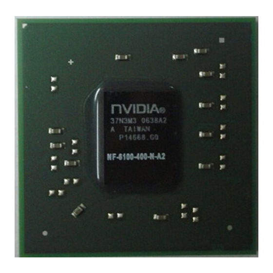
Chipset The board is designed with nVidia nF6100-400 / nF6100-405 / nF6100-430 chipset, featuring performance and stability with the most innovative technology and features. For more details about the nVidia chipset, please visit the nVidia Web site at http://www.nVidia.com. -
Page 7: Special Features
Introduction Special Features Thunder Probe A hardware diagnostic software to monitor voltage, temperature and speed of a variety of hardware. It also includes an ingenious built in fan control feature called Smart Fan. Magic Flash An automatic BIOS update utility in Windows environment, making DOS-based flash utility or bootable diskette a thing of the past. -
Page 8: Mainboard Specification
One IDE interface (up to 2 IDE devices) with UDMA-33/66/100/133 support from embedded IDE controller S-ATA RAID Two S-ATA II ports with up to 300MB/s bandwidth from nF6100-400/nF6100-405, support RAID 0, 1 (Optional) Four S-ATA II ports with up to 300MB/s bandwidth from nF6100-430, support RAID 0, 1, 0+1 (Optional) Onboard EPoX EP1308 LPC bus I/O controller Legacy peripheral interface for PS/2 keyboard &... - Page 9 Three Audio jacks Onboard connector and pin-header One floppy drive connector One ATA-100/133 IDE connector Four extra USB2.0 ports from nF6100-400/nF6100-405 chipest, or Six extra USB2.0 ports from nF6100-430 chipest One CD-IN connector One IR connector One serial port (COM2) connector...
-
Page 10: System Block Diagram
Introduction Support Magic Flash - An automatic BIOS update utility in Windows environment, making DOS-based flash utility or bootable diskette a thing of the past. Support Magic Screen - Software utility to personalize the boot-up screen with your favorite images or logos. -
Page 11: Installation
Introduction Section 2 -- Installation Always have the power supply unplugged and powered off when inserting and removing devices within the computer chassis. 2-1 CPU Installation Step 1 Open the socket by raising the actuation lever. Step 2 (1) Align pin 1 on the CPU with pin 1 on the CPU socket as shown. Insert the CPU and make sure it is fully inserted into the socket. -
Page 12: Jumper Settings
Introduction 2-2 Jumper Settings JCMOS: Clear CMOS data Jumper If the CMOS data becomes corrupted or you forgot the supervisor or user password, clear the CMOS data to reconfigure the system back to the default values stored in the ROM BIOS. Settings: 1-2: Normal (Default) 2-3: Clear CMOS... -
Page 13: System Memory Configuration
Introduction 2-3 System Memory Configuration The mainboard accommodates Four 240-pin DDR2 DIMMs. • Supports up to 16GB of 533/667/800MHz DDR2 SDRAM. • Supports unbuffered DIMM configurations defined in JEDEC DDR2 DIMM specification. Dual Channel interface: • Dual channel memory access offers increased system performance. •... -
Page 14: Rear Io Port
Introduction 2-4 Rear IO Port The I/O back panel for this mainboard is shown below. When installing the mainboard into the computer case, use the bundled I/O shield to protect this back panel. RJ-45 Parallel Port Line-in/Rear out (Light blue) PS/2 Line-out/Front out (Lime) Mouse... - Page 15 CD_IN_Right These connectors are used to receive audio from a CD-ROM CD-IN CD_Reference drive, TV tuner or MPEG card. CD_IN_Left CUSB3~CUSB4: Four USB2.0 header from nF6100-400/ nF6100-405, or CUSB3 CUSB4 CUSB3~CUSB5: Six USB2.0 header from nF6100-430 CUSB5 This mainboard includes additional onboard USB ports.
- Page 16 Connects to the case’s speaker for PC beeps. SATA1 ~ SATA4: Four Serial ATA II Connectors from nF6100-430, SATA1 SATA2 SATA1 ~ SATA2: Two Serial ATA II Connectors from nF6100-400/ SATA3 nF6100-405 SATA4 These connectors enable you to connect Serial ATA HDDs or optical drives type.
-
Page 17: Bios Setup
Introduction Section 3 -- BIOS Setup 3-1 Main Menu The ROM BIOS contains a built-in Setup program which allows user to modify the basic system configuration and hardware parameters. The modified data is stored in a battery-backed CMOS, so that data will be retained even when the power is turned off. -
Page 18: Standard Cmos Setup
Introduction 3-2 Standard CMOS Setup Choose “STANDARD CMOS FEATURES” in the CMOS SETUP UTILITY Menu. Standard CMOS Features Setup allows the user to configure system settings such as the current date and time, type of hard disk drive installed, floppy drive type, and display type. -
Page 19: Init Display First
Introduction Init Display First This item is used to select whether to initialize the PCI-E or PCI first when the system boots. Options: PCI Slot, PCIEx. First /Second/Third Boot Device The BIOS attempts to load the operating system from the devices in the sequence selected in these items. Options: Floppy, LS120, Hard Disk, CDROM, ZIP100, USB-FDD, USB-ZIP, USB-CDROM, Legacy LAN, Disabled. -
Page 20: Power Bios Features
Introduction 3-4 POWER BIOS Features This page lets you adjust various parameters to obtain improved performance for overclocking. Warning: Overclocking requires expert knowledge and risks permanent damage to system components. We recommend you leave these parameters at their default values for proper operation. CPU Overclock Frequency Enables you to increment the CPU’s clock generator at 1 MHz step. -
Page 21: Dimm Voltage
Introduction DIMM Voltage This item allows you to adjust the DIMM slot voltage. Options: Auto, +1.8V to +2.5V in 0.1V increments. We recommend that you leave this at the default value. Memory clock This item sets the memory clock. CPU Core Clock Multiplier vs. DRAM Interface Speed DDRII 400 DDRII 533 DDRII 667... -
Page 22: Section 4-- Driver & Utility
This item installs all drivers automatically. Method 2 This item allows you to install the drivers selectively. Step 1 : Click “nVIDIA nForce Driver” to install chipset driver. Step 2 : Click “REALTEK High Definition Audio Driver” to install audio driver. Step 3 : Click “AMD Cool’n’Quiet Processor Driver”... -
Page 23: Section 5-- Flashing The Bios
Introduction Section 5 -- Flashing the BIOS Do NOT flash the system BIOS unless it is really necessary. Updating and flashing the BIOS content risks BIOS data corruption which may cause system unable to power-on. Download the xxxxx.EXE file corresponding to your model from our website to an empty directory on your hard disk or floppy. - Page 24 Introduction...