Nvidia 680i LT SLI User Manual
Hide thumbs
Also See for 680i LT SLI:
- Hardware user manual (80 pages) ,
- User manual (78 pages) ,
- Overview (2 pages)
Table of Contents
Advertisement
Quick Links
Advertisement
Table of Contents
Troubleshooting

Related Manuals for Nvidia 680i LT SLI


Summary of Contents for Nvidia 680i LT SLI
- Page 1 System Board User’s Manual 935-N68ST1-100G 94500650...
- Page 2 Copyright This publication contains information that is protected by copyright. No part of it may be reproduced in any form or by any means or used to make any transformation/adaptation without the prior written permission from the copyright holders. This publication is provided for informational purposes only. The manufacturer makes no representations or warranties with respect to the contents or use of this manual and specifically disclaims any express or implied warranties of merchantability or fitness for any...
-
Page 3: Fcc And Doc Statement On Class B
FCC and DOC Statement on Class B This equipment has been tested and found to comply with the limits for a Class B digital device, pursuant to Part 15 of the FCC rules. These limits are designed to provide reasonable protection against harmful interference when the equipment is operated in a residential installation. -
Page 4: Table Of Contents
Table of Contents About this Manual................Warranty....................Registering the Product............... Static Electricity Precaution..............Safety Measures..................About the Package................Before Using the System Board............Chapter 1 - Introduction..............Specifications........................... Features.............................. Français..............................Deutsch............................... Español..............................Ðóññêèé ÿçûê......................... Japanese............................. Chapter 2 - Hardware Installation............ System Board Layout ...................... -
Page 5: About This Manual
About this Manual An electronic file of this manual is included in the CD. To view the user’s manual, insert the CD into a CD-ROM drive. The autorun screen will appear. Click the “TOOLS” icon then click “Manual” on the main menu. -
Page 6: Registering The Product
Introduction Registering the Product We encourage you to register your DFI product online. DFI’s product registration service entitles you to notifications about product updates, special discounts and/or promotional offers; and puts your licensing information on file so that we may efficiently assist you if in any case needed. - Page 7 Introduction 3. The DFI Product Registration page will appear. Click Next to continue. 4. Select or fill in the necessary information to complete the registration. 5. Thank you for registering your DFI product.
-
Page 8: Static Electricity Precaution
Introduction Static Electricity Precautions It is quite easy to inadvertently damage your PC, system board, components or devices even before installing them in your system unit. Static electrical discharge can damage computer components without causing any signs of physical damage. You must take extra care in handling them to ensure against electrostatic build-up. -
Page 9: About The Package
Introduction About the Package The system board package contains the following items. If any of these items are missing or damaged, please contact your dealer or sales representative for assistance. One system board One Karajan audio module One SLI bridge One IDE round cable One floppy round cable Four Serial ATA data cables... -
Page 10: Chapter 1 - Introduction
• Dual channel (128-bit wide) memory interface • Up to 8GB system memory • Non-ECC x8 and x16 unbuffered DIMMs • NVIDIA SLI-Ready Memory with EPP Expansion Slots • 3 PCI Express x16 slots - SLI technology - 2 x16 slots both operate at full-bandwidth... - Page 11 • One IDE connector allows connecting up to two UltraDMA 133Mbps hard drives ® Serial ATA with • Six Serial ATA ports supported by NVIDIA MCP55P RAID - SATA speed up to 3Gb/s - RAID 0, RAID 1, RAID 0+1 and RAID 5 •...
-
Page 12: Features
Technology For more information on Hyper-Threading Technology, go to: www.intel.com/info/hyperthreading. ® The NVIDIA (Scalable Link Interface) technology connects two SLI-ready PCI Express graphics cards in a single and scalable system. The two identical graphics cards, which are connected via the SLI bridge, allows us- ers to intelligently scale graphics performance. - Page 13 Introduction nForce 680i LT SLI MCP automatically SLI-ready memory increases bandwidth when selected SLI with EPP Certified memory modules are detected. This allows automatic access to special memory performance. CPU Overheat Protection has the capability of CPU Overheat Protection monitoring the CPU’s temperature during sys- tem boot up.
- Page 14 CD recorders. Serial ATA is a storage interface that is compli- ® ant with SATA 1.0 specification. NVIDIA MCP55P and Silicon Image SiI 3132 both support speed of up to 3Gb/s. Serial ATA improves hard drive performance faster than the standard parallel ATA whose data transfer rate is 100MB/s.
- Page 15 Introduction IEEE 1394 is fully compliant with the 1394 OHCI (Open Host Controller Interface) 1.1 specification. It supports up to 63 devices that can run simultaneously on a system. 1394 is a fast external bus standard that supports data transfer rates of up to 400Mbps. In addition to its high speed, it also supports isochronous data transfer which is ideal for video de- vices that need to transfer high levels of data in real-time.
- Page 16 Introduction The RTC installed on the system board allows your system to automatically power-on on the set date and time. The system board is designed to meet the ACPI (Ad- vanced Configuration and Power Interface) specification. ACPI has energy saving features that enables PCs to implement Power Management and Plug-and-Play with operating systems that ®...
-
Page 17: Français
• L’interface de mémoire deux canaux (128-bit) • Jusqu’à 8GB de mémoire système • Exclusivement les modules DIMM non-ECC x8 et x16 • Les DIMM non-tamponnés • Mémoire SLI-Prête de NVIDIA avec EPP Logements • 3 slots PCI Express x16 d’Extension... - Page 18 • Interface entrée/sor tie S/PDIF • Supporte des disques durs jusqu’à UltraDMA 133Mbps ® Serial ATA avec • 6 ports de série ATA gérés avec la puce NVIDIA MCP55P RAID - Vitesse SATA jusqu’à 3Gb/s - RAID 0, RAID 1, RAID 0+1 et RAID 5 •...
-
Page 19: Deutsch
• 128-bit – Speiher mit den zwei Kanälen • Bis zum 8GB-Systemspeicher • Nur non-ECC x8 und x16 ohne Dämpfer DIMMs • NVIDIA SLI-Ready Memory mit EPP Expansion Schlitz • 3 PCI Express x16-Einbauplätzen - SLI Technologie – 2 x16 Steckplätze arbeiten mit voller Bandbreite und 16 Lanes - Der dritte Steckplatz für physikalische Karten arbeitet mit x8... - Page 20 • Unterstützung der Festplatten bis zum UltraDMA 133Mbps ® Serial ATA mit RAID • 6 serielle Serial ATA-Por ts, unterstützt von einem NVIDIA MCP55P - SATA bis zu 3Gb/s schnell - RAID 0, RAID 1, RAID 0+1 und RAID 5 •...
-
Page 21: Español
• DDR2 533, DDR2 667 y DDR2 800 DIMMs • Memoria de dos canales (128-bit) • Hasta 8GB de memoria sistémica • Sólo non-ECC x8 y x16 unbuffered DIMM • Memoria con EPP compatible con SLI NVIDIA Ranuras de • 3 slots PCI Express x16 Expansión - Tecnología SLI - 2 slots x16 que trabajan con un ancho de... - Page 22 • Interfáz de S/PDIF-in/out •Sopor ta las unidades duras hasta de UltraDMA 133Mbps ® Serial ATA con • 6 ports de Serial ATA soporta por NVIDIA MCP55P RAID - SATA se acelera a 3Gb/s - RAID 0, RAID 1, RAID 0+1 y RAID 5 •...
-
Page 23: Ðóññêèé Ÿçûê
Ïàìÿòü Ïàìÿòü • DDR2 533, DDR2 667 è DDR2 800 DIMMs • äâóõêàíàëüíóþ ïàìÿòü (128-áèò) • äî 8ÃÁ ñèñòåìíîé ïàìÿòè • òîëüêî non-ECC x8 è x16 íåáóôô. DIMM • NVIDIA SLI-Ready ïàìÿòü ñ òåõíîëîãèåé EPP óïðàâëåíèå óïðàâëåíèå óïðàâëåíèå óïðàâëåíèå óïðàâëåíèå... - Page 24 • Ïîääåðæèâàåò æåñòêèå äèñêè äî UltraDMA 133Mbps Serial A Serial A Serial A Serial A Serial AT T T T T A c • 6 SATA ïîðòîâ ïîääåðæàííûõ NVIDIA MCP55P ® R A I D R A I D R A I D...
-
Page 25: Japanese
Introduction • ® ® ® ® ® ® ® • • • • ® • ® ® • • • • • • • • • • • • • • • • • • • • • • • •... - Page 26 Introduction ® ® ®...
-
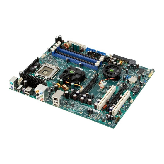
Page 27: Chapter 2 - Hardware Installation
Hardware Installation Chapter 2 - Hardware Installation System Board Layout... -
Page 28: System Memory
Hardware Installation Warning: Electrostatic discharge (ESD) can damage your system board, processor, disk drives, add-in boards, and other components. Perform the upgrade instruction procedures described at an ESD workstation only. If such a station is not available, you can provide some ESD protection by wearing an antistatic wrist strap and attaching it to a metal part of the system chassis. - Page 29 Hardware Installation The system board supports the following memory interface. Single Channel (SC) Data will be accessed in chunks of 64 bits (8B) from the memory channels. Dual Channel (DC) Data will be accessed in chunks of 128 bits from the memory chan- nels.
-
Page 30: Installing The Dim Module
Hardware Installation Installing the DIM Module 1. Make sure the PC and all other peripheral devices connected to it has been powered down. 2. Disconnect all power cords and cables. 3. Locate the DDR2 socket on the system board. 4. Push the “ejector tabs” which are at the ends of the socket to the side. - Page 31 Hardware Installation 6. Grasping the module by its edges, position the module above the socket with the “notch” in the module aligned with the “key” on the socket. The keying mechanism ensures the module can be plugged into the socket in only one way. 7.
-
Page 32: Cpu
Hardware Installation Overview The system board is equipped with a surface mount LGA 775 socket. This socket is exclusively designed for installing a LGA 775 packaged Intel CPU. Important: 1. Before you proceed, make sure (1) the LGA775 1. Before you proceed, make sure (1) the LGA775 1. - Page 33 Hardware Installation Important: The CPU socket must not come in contact with anything other than the CPU. Avoid unnecessary exposure. Remove the protective cap only when you are about to install the CPU. 4. The CPU socket comes with a cover that is attached with a re- movable protective cap.
- Page 34 Hardware Installation 7. Now lift the cover. Cover 8. Position the CPU above the socket. The gold mark on the CPU must align with pin 1 of the CPU socket. Important: Handle the CPU by its edges and avoid touching the pins. Gold mark Pin 1 of the socket...
- Page 35 Hardware Installation 9. Insert the CPU into the socket until it is seated in place. The CPU will fit in only one orientation and can easily be inserted without exerting any force. Important: Do not force the CPU into the socket. Forcing the CPU into the socket may bend the pins and damage the CPU.
-
Page 36: Installing The Fan And Heat Sink
Hardware Installation 11. Push the lever down to lock the socket. The lever should hook onto the side tab to indicate that the CPU is completely se- cured in the socket. Installing the Fan and Heat Sink The CPU must be kept cool by using a CPU fan with heat sink. Without sufficient air circulation across the CPU and heat sink, the CPU will overheat damaging both the CPU and system board. - Page 37 Hardware Installation 2. Place the heat sink on top of the CPU. The 4 studs around the heat sink which are used to secure the heat sink onto the sys- tem board must match the 4 mounting holes around the socket. Position each stud so that the groove faces the heat sink then push it down firmly until it clicks into place.
-
Page 38: Jumper Settings
Hardware Installation Jumper Settings Clear CMOS Data Clearing CMOS Data using JP2 1-2 On: Normal 2-3 On: (default) Clear CMOS Data If you encounter the following, a) CMOS data becomes corrupted. b) You forgot the supervisor or user password. c) You are unable to boot-up the computer system because the processor’s clock was incorrectly set in the BIOS. - Page 39 Hardware Installation 4. After powering-on the system, press <Del> to enter the main menu of the BIOS. 5. Select the Advanced Chipset Features submenu (“System Clocks” section) and press <Enter>. 6. Set the processor’s clock to its default setting or an appropriate setting.
- Page 40 Hardware Installation ® Clearing CMOS Data using the EZ Clear Function ® EZ Clear bypasses the manual process of clearing CMOS by simply using the reset and power button. Important: ® EZ Clear is supported only if standby power is present in the system.
- Page 41 Hardware Installation PS/2 Power Select 1-2 On: 5V 2-3 On: (default) 5VSB JP7 is used to select the power of the PS/2 keyboard/mouse port. Selecting 5VSB will allow you to use the PS/2 keyboard or PS/2 mouse to wake up the system. BIOS Setting Configure the PS/2 keyboard/mouse wake up function in the Integrated Peripherals submenu of the BIOS.
-
Page 42: Usb Power Select
Hardware Installation USB Power Select USB 1-6 (JP5) 1-2 On: 5V 2-3 On: (default) 5VSB USB 7-10 (JP6) 1-2 On: 5V 2-3 On: (default) 5VSB JP5 and JP6 are used to select the power of the USB ports. Selecting 5VSB will allow you to use the USB keyboard or USB mouse to wake up the system.. - Page 43 Hardware Installation Speaker On/Off Select Buzzer 2-3 On: 1-2 On: Speaker On Speaker Off (default) The system board is equipped with a buzzer which serves as the PC’s speaker. By default the buzzer is “on” allowing you to hear the system’s beep messages and warnings.
- Page 44 Hardware Installation Safe Boot 2-3 On: 1-2 On: Default Safe boot JP1 is used to safely reboot the system whenever the system hangs and you are unable to restart the system. 1. Power-off the system and unplug the power cord. 2.
- Page 45 Hardware Installation PCIE 3 Setting JP11 1-2 On: 2-3 On: Default PCIE card present in PCIE 3 slot PCIE 3 slot If a PCIE card is present in the PCIE 3 slot, set JP11 pins 2 and 3 to On.
- Page 46 Hardware Installation S/PDIF-out Select JP52 1-2 On: 2-3 On: S/PDIF-out via S/PDIF-out via ALC885 NVIDIA chip JP52 is used to select the controller that will send signal to the S/PDIF-out port.
-
Page 47: Rear Panel I/O Ports
Hardware Installation Rear Panel I/O Ports Front R/L (Line-out) PS/2 Line-in Mic-in LAN 1 LAN 2 Mouse 1394-1 S/PDIF-in PS/2 USB 1-2 USB 3-4 USB 5-6 S/PDIF-out Rear R/L Center/ Side R/L Subwoofer Karajan audio module The rear panel I/O ports consist of the following: •... - Page 48 Hardware Installation PS/2 Mouse and PS/2 Keyboard Ports PS/2 Mouse PS/2 Keyboard The onboard PS/2 mouse (Green) and PS/2 keyboard (Purple) ports are both at location CN2 of the system board. The PS/2 mouse port uses IRQ12. If a mouse is not connected to this port, the system will reserve IRQ12 for other expansion cards.
- Page 49 Hardware Installation S/PDIF-in/out Jacks S/PDIF-in S/PDIF-out SPDIF out SPDIF in Optical S/PDIF The system board is equipped with an onboard S/PDIF-in RCA jack (red) and a S/PDIF-out RCA jack (yellow) at locations CN5 and CN7 respectively. The S/PDIF connector at location J3 is used to connect optical S/PDIF por ts.
- Page 50 Hardware Installation Karajan Audio Module Line-in Mic-in Front R/L (Line-out) Karajan audio module Rear R/L Side R/L Center/ Subwoofer Karajan audio connector Installing the Karajan Audio Module The system board package includes a Karajan audio module and the module holder. The module holder is used to stabilize the Karajan audio module onto the system board.
- Page 51 Hardware Installation 1. Fit the module holder onto the Karajan audio module. 2. Align the module’s plugs above the mounting holes then insert the plugs from the top through to the bottom of the system board. While at it, the 14-pin connector at the solder side of the module must also insert into the Karajan audio connector at location J7 of the system board.
- Page 52 Hardware Installation Note: The illustrations in this section are for reference only. The sys- tem board and the color of the module holder may differ from the actual one. Uninstalling the Karajan Audio Module The Karajan audio module is snapped through the system board via the module holder.
- Page 53 Hardware Installation Front Audio The front audio connector (J4) on the Karajan audio module allows you to connect to the line-out and mic-in jacks that are at the front panel of your system. Using this connector will disable the rear au- dio’s line-out and mic-in functions.
- Page 54 Hardware Installation IEEE 1394 Ports 1394-1 1394-2 The onboard IEEE 1394 port is at location CN3 (IEEE 1394-1) of the system board. It is also equipped with an IEEE 1394 connector at location J8 (1394-2) for connecting an additional 1394 device. The 1394 port may come mounted on a card-edge bracket.
- Page 55 Hardware Installation USB (Universal Serial Bus) Ports USB 2 USB 1 USB 4 USB 3 USB 6 USB 7-8 USB 5 USB 9-10 The system board supports 10 USB 2.0/1.1 ports. USB allows data exchange between your computer and a wide range of simultaneously accessible external Plug and Play peripherals.
- Page 56 Hardware Installation Driver Installation You may need to install the proper drivers in your operating system to use the USB device. Refer to your operating system’s manual or documentation for more information. Refer to chapter 4 for more information about installing the USB 2.0 driver.
-
Page 57: Rj45 Lan Ports
Hardware Installation RJ45 LAN Ports LAN 1 LAN 2 The onboard LAN ports are at locations CN4 (LAN 1) and CN6 (LAN 2) of the system board. LAN allows the system board to connect to a local area network by means of a network hub. BIOS Setting Configure the onboard LAN in the Integrated Peripherals submenu of the BIOS. -
Page 58: Internal I/O Connectors
Hardware Installation I/O Connectors CD-in Internal Audio Connector Ground Ground Left audio Right audio channel channel Audio codec Line-in Front R/L Mic-in Center/Subwoofer Rear R/L Side R/L The CD-in (J2) connector on the Karajan audio module used to receive audio from a CD-ROM drive, TV tuner or MPEG card. -
Page 59: Floppy Disk Drive Connector
Hardware Installation Floppy Disk Drive Connector The system board is equipped with a 90 floppy disk drive connector that supports two standard floppy disk drives. To prevent improper floppy cable installation, the floppy disk header has a keying mechanism. The 34-pin connector on the floppy cable can be placed into the header only if pin 1 of the connector is aligned with pin 1 of the header. -
Page 60: Serial Ata Connectors
Hardware Installation Serial ATA Connectors Serial ATA ports supported by the NVIDIA MCP55P chip SATA 5-6 SATA 3-4 SATA 1-2 • SATA speed up to 3Gb/s • RAID 0, RAID 1, RAID 0+1 and RAID 5 Connecting Serial ATA Cables Connect one end of the Serial ATA cable to the Serial ATA connec- tor and the other end to your Serial ATA device. - Page 61 Hardware Installation Serial ATA ports supported by the Silicon Image SiI3132 chip (LP UT NF680i LT SLI-T2R only) SATA 8 (J21) SATA 7 (J20) • SATA speed up to 3Gb/s • RAID 0, RAID 1 and RAID 0+1 Connecting Serial ATA Cables Connect one end of the Serial ATA cable to the Serial ATA connec- tor and the other end to your Serial ATA device.
-
Page 62: Ide Disk Drive Connector
Hardware Installation IDE Disk Drive Connector The system board is equipped with a shrouded PCI IDE header that will interface two Enhanced IDE (Integrated Drive Electronics) disk drives. To prevent improper IDE cable installation, each shrouded PCI IDE header has a keying mechanism. The 40-pin connector on the IDE cable can be placed into the header only if pin 1 of the connector is aligned with pin 1 of the header. - Page 63 Hardware Installation Adding a Second IDE Disk Drive When using two IDE drives, one must be set as the master and the other as the slave. Follow the instructions provided by the drive manufacturer for setting the jumpers and/or switches on the drives. The system board suppor ts Enhanced IDE or ATA-2, ATA/33, ATA/66, ATA/100 or ATA/133 hard drives.
- Page 64 Hardware Installation Serial (COM) Port The system board is equipped with a 9-pin connector for connecting an external serial port. The serial port cable is an optional item and must be purchased separately. Insert the connector that is attached to the serial port cable to the 9-pin connector (J4) then install the serial port bracket to an available bracket slot at the rear of the system chassis.
- Page 65 Hardware Installation IrDA and CIR Connectors CIRTX IRTX Ground Ground CIRRX IRRX N. C. N. C. 5VSB IrDA CIR Connect the cable connector from your IrDA module to the IrDA connector (J5) or CIR connector (J14). Note: The sequence of the pin functions on some IrDA/CIR cable may be reversed from the pin function defined on the system board.
-
Page 66: Cooling Fan Connectors
Hardware Installation Cooling Fan Connectors Ground Power Sense Speed Control CPU fan Power Ground N. C. N. C. Power Ground Fan 3 Fan 2 Power Ground N. C. Ground N. C. Fan 1 Power Power Fan 5 Ground N. C. Fan 4 Connect the CPU fan’s cable connector to the CPU fan connector (J31) on the system board. - Page 67 Hardware Installation LEDs DRAM Power LED Standby Diagnostic Power LED DRAM Power LED This LED will light when the system’s power is on. Standby Power LED This LED will light when the system is in the standby mode. Diagnostic LED The Diagnostic LED displays POST codes.
-
Page 68: Power Connectors
Hardware Installation Power Connectors Use a power supply that complies with the ATX12V Power Supply Design Guide Version 1.1. An ATX12V power supply unit has a standard 24-pin ATX main power connector that must be inserted onto CN10. 1 2 2 4 +3.3VDC +12VDC +5VDC... - Page 69 Hardware Installation The FDD-type power connectors are additional power connector.s If you are using more than one graphics cards, we recommend that you plug a power cable from your power supply unit onto the 5V/12V power connectors at locations J1 and/or J13. This will pro- vide more stability to the entire system.
- Page 70 Hardware Installation Restarting the PC Normally, you can power-off the PC by: 1. Pressing the power button at the front panel of the chassis. 2. Pressing the power switch that is on the system board (note: not all system boards come with this switch). If for some reasons you need to totally cut off the power supplied to the PC, switch off the power supply or unplug the power cord.
-
Page 71: Front Panel Connectors
Hardware Installation Front Panel Connectors RESET SPEAKER HD-LED PWR-LED ATX-SW HD-LED: Primary/Secondary IDE LED This LED will light when the hard drive is being accessed. RESET: Reset Switch This switch allows you to reboot without having to power off the system thus prolonging the life of the power supply or system. - Page 72 Hardware Installation PWR-LED: Power/Standby LED When the system’s power is on, this LED will light. When the system is in the S1 (POS - Power On Suspend) or S3 (STR - Suspend To RAM) state, it will blink every second. Note: If a system did not boot-up and the Power/Standby LED did not light after it was powered-on, it may indicate that the CPU...
- Page 73 Hardware Installation EZ Touch Switches Reset Power The presence of the power switch and reset switch on the system board are user-friendly especially to DIY users. They provide convenience in powering on and/or resetting the system while fine tuning the system board before it is installed into the system chassis.
- Page 74 Hardware Installation PCI Express Slots PCI Express x16 PCI Express x4 PCI Express x16 PCI Express x16 PCI Express x16 Install PCI Express x16 graphics card, that comply to the PCI Ex- press specifications, into the PCI Express x16 slot. To install a graph- ics card into the x16 slot, align the graphics card above the slot then press it down firmly until it is completely seated in the slot.
- Page 75 Hardware Installation Battery The lithium ion battery powers the real-time clock and CMOS memory. It is an auxiliary source of power when the main power is shut off. Safety Measures • Danger of explosion if battery incorrectly replaced. • Replace only with the same or equivalent type recommend by the manufacturer.
-
Page 76: Chapter 3 - Bios Setup
BIOS Setup Chapter 3 - BIOS Setup Award BIOS Setup Utility The Basic Input/Output System (BIOS) is a program that takes care of the basic level of communication between the processor and pe- ripherals. In addition, the BIOS also contains codes for various ad- vanced features found in this system board. - Page 77 BIOS Setup Standard CMOS Features Use the arrow keys to highlight “Standard CMOS Features” then press <Enter>. A screen similar to the one below will appear. Phoenix - AwardBIOS CMOS Setup Utility Standard CMOS Features Tue, Jan 2 2007 Date <mm:dd:yy> Item Help Time <hh:mm:ss>...
- Page 78 BIOS Setup Primary IDE Master/Slave and Internal Phy SATA 1/2/3/4/5/6 Primary IDE Master Used to configure Parallel ATA drives Primary IDE Slave Internal Phy SATA 1 Internal Phy SATA 2 Internal Phy SATA 3 Used to configure Serial ATA drives Internal Phy SATA 4 Internal Phy SATA 5 Internal Phy SATA 6...
- Page 79 BIOS Setup Primary IDE Master and Primary IDE Slave The drive type information should be included in the documentation from your hard disk vendor. If you select ”Auto”, the BIOS will auto- detect the HDD & CD-ROM drive at the POST stage and show the IDE for the HDD &...
- Page 80 BIOS Setup To configure Serial ATA drives, move the cursor to a field then press <Enter>. The following screen will appear. Phoenix - AwardBIOS CMOS Setup Utility Internal Phy SATA 1 IDE Auto-Detection Press Enter Item Help Auto Extended IDE Drive Menu Level Access Mode Auto...
- Page 81 BIOS Setup Cylinder This field displays the number of cylinders. Head This field displays the number of read/write heads. Precomp This field displays the number of cylinders at which to change the write timing. Landing Zone This field displays the number of cylinders specified as the landing zone for the read/write heads.
- Page 82 BIOS Setup Drive A This field identifies the type of floppy disk drive installed. None No floppy drive is installed 360K, 5.25 in. 5-1/4 in. standard drive; 360KB capacity 1.2M, 5.25 in. 5-1/4 in. AT-type high-density drive; 1.2MB capacity 720K, 3.5 in. 3-1/2 in.
- Page 83 BIOS Setup Base Memory Displays the amount of base (or conventional) memory installed in the system. The value of the base memory is typically 512K for systems with 512K memory installed on the motherboard or 640K for systems with 640K or more memor y installed on the motherboard.
-
Page 84: Advanced Bios Features
BIOS Setup Advanced BIOS Features The Advanced BIOS Features allows you to configure your system for basic operation. Some entries are defaults required by the system board, while others, if enabled, will improve the performance of your system or let you set some features according to your preference. Phoenix - AwardBIOS CMOS Setup Utility Advanced BIOS Features CPU Feature... - Page 85 BIOS Setup Many disk diagnostic programs which attempt to access the boot sec- tor table will cause the warning message to appear. If you are running such a program, we recommend that you first disable this field. CPU L1 and L2 Cache This field is used to speed up the memory access.
- Page 86 BIOS Setup Boot Up NumLock Status This allows you to determine the default state of the numeric keypad. By default, the system boots up with NumLock on wherein the function of the numeric keypad is the number keys. When set to Off, the function of the numeric keypad is the arrow keys.
- Page 87 BIOS Setup Delay For HDD (Secs) This field is used to select the time that would delay the HDD controller’s initial time. This is specially useful for some HDDs which will not be ready at first boot when you power-on the system. Full Screen Logo Show This field is applicable only if you want a particular logo to appear during system boot-up.
- Page 88 BIOS Setup CPU Feature Move the cursor to this field and press <Enter>, the following screen will appear: Phoenix - AwardBIOS CMOS Setup Utility CPU Feature CPU Core Unlock Disabled Item Help Thermal Monitor 1 Thermal Management Menu Level TM2 Bus Ratio TM2 Bus VID 0.8375 Set Limit CPUID...
- Page 89 BIOS Setup TM2 Bus VID This field is used to select the voltage of the throttled performance state that will be initiated when the on-die sensor turns from cool to hot. Limit CPUID MaxVal The CPUID instruction of some newer CPUs will return a value greater than 3.
-
Page 90: Removable Device Priority
BIOS Setup Removable Device Priority This field is used to select the boot sequence of the removable devices. Move the cursor to this field then press <Enter>. Use the Up or Down arrow keys to select a device then press <+> to move it up or <->... - Page 91 BIOS Setup Hard Disk Boot Priority This field is used to select the boot sequence of the hard drives. Move the cursor to this field then press <Enter>. Use the Up or Down arrow keys to select a device then press <+> to move it up or <->...
-
Page 92: Advanced Chipset Features
Advanced Chipset Features Phoenix - AwardBIOS CMOS Setup Utility Advanced Chipset Features System BIOS Cacheable Disabled Item Help Video RAM Cacheable Disabled Menu Level NVIDIA GPU Ex Disable ↑↓→← : Move Enter: Select +/-/PU/PD: Value F10: Save ESC: Exit F1: General Help... - Page 93 When enabled, it allows the video RAM to be cacheable thus pro- viding better video performance. If your graphics card does not sup- port this function, set this field to Disabled. NVIDIA GPU Ex The options are Enabled and Disabled.
-
Page 94: Integrated Peripherals
BIOS Setup Integrated Peripherals Phoenix - AwardBIOS CMOS Setup Utility Integrated Peripherals IDE Function Setup Press Enter Item Help RAID Config Press Enter Menu Level OnChip USB Controller V1.1+V2.0 USB Memory Type SHADOW USB KB/Storage Support Disabled USB Mouse Support Disabled USB Park Mode Enabled... - Page 95 BIOS Setup USB KB/Storage Support Due to the limited space of the BIOS ROM, the support for legacy USB keyboard/storage (in DOS mode) is by default set to Disabled. With more BIOS ROM space available, it will be able to support more advanced features as well as provide compatibility to a wide variety of peripheral devices.
- Page 96 BIOS Setup HD Audio Auto The system automatically detects the onboard High Definition audio CODEC. Disabled Disables the onboard audio. Disable the onboard audio when using an audio PCI card. MAC Lan Auto The system automatically detects the onboard LAN 1. Disabled Disables the onboard LAN 1.
- Page 97 BIOS Setup Power On By Button To use the power button to power on the system, set this field to Enabled. KB Power On Password Move the cursor to this field and press <Enter>. Enter your password. You can enter up to 5 characters. Type in exactly the same password to confirm, then press <Enter>.
- Page 98 BIOS Setup PWRON After PWR-Fail When power returns after an AC power failure, the system’s power is off. You must press the Power but- ton to power-on the system. When power returns after an AC power failure, the system will automatically power-on. Former-Sts When power returns after an AC power failure, the system will return to the state where you left off...
- Page 99 BIOS Setup IDE Function Setup Phoenix - AwardBIOS CMOS Setup Utility IDE Function Setup Item Help Primary IDE Enabled Primary Master PIO Auto Menu Level Primary Slave PIO Auto Primary Master UDMA Auto Primary Slave UDMA Auto IDE DMA Transfer Access Enabled IDE Prefetch Mode Enabled...
- Page 100 BIOS Setup Primary Master UDMA and Primary Slave UDMA These fields allow you to set the Ultra DMA in use. When Auto is selected, the BIOS will select the best available option after checking your hard drive or CD-ROM. Auto The BIOS will automatically detect the settings for you.
-
Page 101: Raid Config
RAID Enable This field is used to enable or disable the RAID function of the Serial ATA supported by NVIDIA MCP55P. Internal Phy SATA 1 RAID to Internal Phy SATA 6 RAID These fields are used to enable or disable the RAID function of... -
Page 102: Power Management Setup
BIOS Setup Power Management Setup The Power Management Setup allows you to configure your system to most effectively save energy. Phoenix - AwardBIOS CMOS Setup Utility Power Management Setup Enabled ACPI Function Item Help S1&S3 ACPI Suspend Type Menu Level Power Management User Define Video Off Method... - Page 103 BIOS Setup Power Management This field allows you to select the type (or degree) of power saving by changing the length of idle time that elapses before the “HDD Power Down” field is activated. Min Saving Minimum power saving time for the “HDD Power Down”...
- Page 104 BIOS Setup Soft-Off by PWRBTN This field allows you to select the method of powering off your system. Delay 4 Sec. Regardless of whether the Power Management function is enabled or disabled, if the power but- ton is pushed and released in less than 4 sec, the system enters the Suspend mode.
- Page 105 BIOS Setup Day of Month Alarm The system will power-on everyday according to the time set in the “Time (hh:mm:ss) Alarm” field. 1-31 Select a date you would like the system to power-on. The system will power-on on the set date, and time set in the “Time (hh:mm:ss) Alarm”...
-
Page 106: Init Display First
BIOS Setup PnP/PCI Configurations This section describes configuring the PCI bus system. It covers some very technical items and it is strongly recommended that only experienced users should make any changes to the default settings. Phoenix - AwardBIOS CMOS Setup Utility PnP/PCI Configurations Init Display First PCI Slot... -
Page 107: Resources Controlled By
BIOS Setup Resources Controlled By The Award Plug and Play BIOS has the capability to automatically configure all of the boot and Plug and Play compatible devices. Auto(ESCD) The system will automatically detect the settings for you. Manual Choose the specific IRQ in the “IRQ Resources” field. - Page 108 BIOS Setup PCI Latency Timer (Per 8CLK) This feature is used to select the length of time each PCI device will control the bus before another takes over. The larger the value, the longer the PCI device can retain control of the bus. Since each ac- cess to the bus comes with an initial delay before any transaction can be made, low values for the PCI Latency Timer will reduce the effectiveness of the PCI bandwidth while higher values will improve it.
-
Page 109: Pc Health Status
BIOS Setup PC Health Status Phoenix - AwardBIOS CMOS Setup Utility PC Health Status C/185 Shutdown Temperature Item Help CPUFan Fully ON If CPUTemp > 50 Menu Level CPUFan Turn OFF If CPUTemp < 25 CHSFan Fully ON If CHSTemp >... - Page 110 BIOS Setup On If CPUTemp” field to allow the CPU fan to rotate full speed at the selected lower temperature. CHSFan Fully On If CHSTemp This field is used to select the system’s temperature at which the chassis fan will rotate at full speed. CHSFan Turn Off If CHSTemp This field is used to select the system’s temperature at which the chassis fan will rotate at a start speed which is the slowest speed.
-
Page 111: Genie Bios Setting
BIOS Setup Genie BIOS Setting Phoenix - AwardBIOS CMOS Setup Utility Genie BIOS Setting Item Help Voltage Control Press Enter FSB & Frequency Setting Press Enter Menu Level Memory Timing Setting Press Enter LDT Frequency Disabled SiI3132 SATA RAID Control CPU Clock Ratio 1.28V ↑↓→←... - Page 112 BIOS Setup Voltage Control Move the cursor to this field and press <Enter>, the following screen will appear: Phoenix - AwardBIOS CMOS Setup Utility Voltage Control Auto CPU VID Control Item Help Auto CPU VID Special Add Menu Level DRAM Voltage Control 1.85V NB +1.4V +1.4000V...
- Page 113 BIOS Setup NB +1.4V This field is used to select the northbridge’s voltage. SB +1.5V This field is used to select the southbridge’s voltage. SB +1.5V Dual This field is used to select the southbridge’s voltage. CPU VTT 1.2V Voltage This field is used to select the voltage supplied to the CPU.
- Page 114 BIOS Setup FSB & Frequency Setting Move the cursor to this field and press <Enter>, the following screen will appear: Phoenix - AwardBIOS CMOS Setup Utility FSB & Frequency Setting Parameters Setting Current Value Item Help Menu Level Current CPU Freq, MHz 1866.7 1866.7 CPU Multiplier...
- Page 115 BIOS Setup MEM (DDR), MHz This field is used to select the memory clock. Actual MEM (DDR), MHz This field will show the actual memory clock. PCIe Bus, Slot 1, Mhz and PCIe Bus, Slot 2, Mhz These fields are used to select the bus clock of the two PCIE slots. SPP<...
- Page 116 BIOS Setup Memory Timing Setting Move the cursor to this field and press <Enter>, the following screen will appear: Phoenix - AwardBIOS CMOS Setup Utility Memory Timing Setting Parameters Setting Item Help Menu Level Memory Timing Setting Optimal CAS Latency Control (Tcl) Auto System Clock Mode RAS# to CAS# Delay (Trcd)
- Page 117 BIOS Setup Min RAS# Active Time (Tras) This field is used to select the minimum time RAS takes to read from and write to a memory cell. Command Per Clock (CPC) This field is used to enable the DRAM commands and address that will be driven for 2 clock cycles and select the second phase of the 2 clock command and address.
-
Page 118: Cmos Reloaded
BIOS Setup CMOS Reloaded The CMOS Reloaded submenu allows you to save different configu- rations and when needed, allows you to conveniently restore one of these previously saved configurations. Highlight CMOS Reloaded in the main menu then press <Enter>. Phoenix - AwardBIOS CMOS Setup Utility CMOS Reloaded Item Help Auto Save Bootable Setting... - Page 119 BIOS Setup Auto Save Bootable Setting This field is used to automatically save the last bootable setting from CMOS to an area in the SEEPROM referred to as the backup bank. To use this function: 1. Set this field to Enabled. 2.
- Page 120 BIOS Setup Saving, Loading and Naming BIOS Settings For overclockers who require different sets of settings for various system environments or operating systems, CMOS Reloaded allows you to save, load and name up to four sets of BIOS settings - in the “User Defined Setting Bank #1”...
- Page 121 BIOS Setup Load from this Bank To load the setting saved in the bank, move the cursor to “Load from this Bank” then press <Enter>. The setting in this bank will replace the current setting. Make sure to save before you exit the BIOS setup utility by selecting “Y”...
-
Page 122: Load Optimized Defaults
BIOS Setup Load Optimized Defaults The “Load Optimized Defaults” option loads optimized settings from the BIOS ROM. Use the default values as standard values for your system. Highlight this option in the main menu and press <Enter>. Phoenix - AwardBIOS CMOS Setup Utility Standard CMOS Features Genie BIOS Setting Advanced BIOS Features... -
Page 123: Set Supervisor Password
BIOS Setup Set Supervisor Password If you want to protect your system and setup from unauthorized entry, set a supervisor’s password with the “System” option selected in the Advanced BIOS Features. If you want to protect access to setup only, but not your system, set a supervisor’s password with the “Setup”... -
Page 124: Set User Password
BIOS Setup Set User Password If you want another user to have access only to your system but not to setup, set a user’s password with the “System” option se- lected in the Advanced BIOS Features. If you want a user to enter a password when trying to access setup, set a user’s password with the “Setup”... - Page 125 BIOS Setup Save & Exit Setup When all the changes have been made, highlight “Save & Exit Setup” and press <Enter>. Phoenix - AwardBIOS CMOS Setup Utility Standard CMOS Features Genie BIOS Setting Advanced BIOS Features CMOS Reloaded Advanced Chipset Features Load Optimized Defaults Integrated Peripherals Set Supervisor Password...
-
Page 126: Exit Without Saving
BIOS Setup Exit Without Saving When you do not want to save the changes you have made, high- light “Exit Without Saving” and press <Enter>. Phoenix - AwardBIOS CMOS Setup Utility Standard CMOS Features Genie BIOS Setting Advanced BIOS Features CMOS Reloaded Advanced Chipset Features Load Optimized Defaults... -
Page 127: Raid Bios
BIOS Setup RAID BIOS NVRAID BIOS The NVRAID BIOS utility is used to configure and manage RAID on Serial ATA drives connected to SATA 1 to SATA 6. After you power up the system and all drives have been detected, the NVRAID BIOS status message screen will appear. -
Page 128: Updating The Bios
BIOS Setup Updating the BIOS To update the BIOS, you will need the new BIOS file and a flash utility, AWDFLASH.EXE. You can download them from DFI’s web site or contact technical support or your sales representative. 1. Save the new BIOS file along with the flash utility AWDFLASH.EXE to a floppy disk. - Page 129 BIOS Setup 6. The following will appear. Do You Want to Save BIOS (Y/N) This question refers to the current existing BIOS in your system. We recommend that you save the current BIOS and its flash utility; just in case you need to reinstall the BIOS. To save the current BIOS, press <Y>...
-
Page 130: Chapter 4 - Supported Softwares
Supported Software Chapter 4 - Supported Software Drivers, Utilities and Software Applications The CD that came with the system board contains drivers, utilities and software applications required to enhance the performance of the system board. Insert the CD into a CD-ROM drive. The autorun screen will appear. If after inserting the CD, "Autorun"... - Page 131 Supported Software nVidia nForce680 System Drivers On the left side of the autorun screen, click the “CHIPSET” icon. 1. Click “nVidia nForce680 System Drivers” on the main menu. 2. Click “I accept the terms in the license agreement” then click Next.
- Page 132 Supported Software 4. Setup is now ready to install the driver. Click Next. 5. Click Yes to install the driver. 6. Select the drivers you want to install. The drivers will be installed automatically. Click “Next” to continue.
- Page 133 Supported Software 7. Read the information about NVIDIA Storage software driver. This driver will replace the Windows ATA driv- ers to enable the proc- essor and other system level hardware to be more productive and efficient. Click Next. 8. Follow the prompts on the screen to complete installation.
- Page 134 Supported Software Microsoft .NET Framework On the left side of the autorun screen, click the “GRAPHICS” icon. 1. Click “Microsoft .NET Framework” on the main menu. 2. Setup is now ready to install the driver, Click Next. 3. Read the license agreent then click “I accept the terms of the License Agreement”.
- Page 135 Supported Software 4. Setup is currently installing the driver. 5. Click Finish to exit setup. Restar t the system to allow the new driver installation to take effect.
- Page 136 Supported Software Graphics Drivers The CD provides both ATI Radeon and nVidia GForce drivers. Install the driver according to the graphics card that you are using. ATI Radeon Driver On the left side of the autorun screen, click the “GRAPHICS” icon.
- Page 137 Supported Software 3. The installation wizard will extract the files needed to install the driver. After files have been extracted, click Next. 4. Setup is now ready to install the driver. Click Next. 5. Read the license agree- ment then click Yes.
- Page 138 Supported Software 6. Select the component you want to install then click Next. 7. Setup is currently installing the driver. 8. Click “Yes, I want to restar t my computer now” then click Finish. Restarting the system will allow the new driver installation to take effect.
- Page 139 Supported Software nVidia GForce Driver On the left side of the autorun screen, click the “GRAPHICS” icon. 1. Click “nVidia GForce Driver” on the main menu. 2. Read the license agree- ment then click “I accept the terms in the license...
- Page 140 3. Click Next to install to the destination folder or click Change to select another folder. 4. Setup is now ready to install NVIDIA Display driver. Click Next. 5. Setup is currently installing the driver on your computer. Follow the prompts on the screen to complete installation.
-
Page 141: Realtek Audio Driver
Supported Software Realtek Audio Driver On the left side of the autorun screen, click the “AUDIO” icon. 1. Click “Realtek Audio Driver” on the main menu. 2. Setup is now preparing to install the driver. Click Next to continue. 3. Setup is now configuring software installation. - Page 142 Supported Software 4. Click “Yes, I want to restar t my computer now” then click Finish. Restarting the system will allow the new driver installation to take effect.
- Page 143 Supported Software RAID Drivers On the left side of the autorun screen, click the “RAID” icon. The RAID Drivers menu includes drivers and utility that must be installed when using RAID configured Serial ATA devices that are supported by the Silicon Image SiI3132 controller.
- Page 144 Supported Software ITE Smart Guardian The ITE Smart Guardian utility is capable of monitoring the system’s tem- perature, fan speed, voltage, etc. and allows you to manually set a range (Highest and Lowest Limit) to the items being monitored. If the settings/ values are over or under the set range, a warning message will pop-up.
- Page 145 Supported Software 3. Type in the necessar y information then click Next. 4. Click Next to install or click Browse to select another folder. 5. Click Next to add the program icon to the Program Folder.
- Page 146 Supported Software 6. Select an option in accordance to your operating system then click Next. 7. Click Finish. Reboot the system for the driver to take effect.
-
Page 147: Installation Notes
Supported Software USB 2.0 Drivers ® Windows ® If your Windows XP CD already includes Service Pack 1, the USB 2.0 driver will automatically install when you install the operating sys- tem. If the CD does not include Service Pack 1, it is available for download at Microsoft’s Windows Update website. -
Page 148: Chapter 5 - Raid
RAID Chapter 5 - RAID ® The NVIDIA MCP55P chip alows configuring RAID on Serial ATA drives. It supports RAID 0, RAID 1, RAID 0+1 and RAID 5. The Silicon Image Sil3132 chip allows configuring RAID on another 2 Serial ATA drives. It supports RAID 0, RAID 1 and RAID 0+1. - Page 149 RAID Settings To enable the RAID function, the following settings are required. 1. Connect the Serial ATA drives. 2. Configure Serial ATA in the Award BIOS. 3. Configure RAID in the NVRAID BIOS and/or Sil3132 SataRAID BIOS. 4. Install RAID driver. Step 1: Connect the Serial ATA Drives SATA 5-6 SATA 3-4...
- Page 150 1. Power-on the system then press <Del> to enter the main menu of the Award BIOS. 2. Select the Integrated Peripherals submenu - RAID Config section of the BIOS to configure SATA supported by the NVIDIA MCP55P chip. Phoenix - AwardBIOS CMOS Setup Utility...
- Page 151 RAID 3. Press <Esc> to return to the main menu of the BIOS setup utility. Select “Save & Exit Setup” then press <Enter>. 4. Type <Y> and press <Enter>. 5. Reboot the system. Step 3: Configure RAID in the RAID BIOS Configure RAID in the NVRAID BIOS When the system powers-up and all drives have been detected, the NVRAID BIOS status message screen will appear.
- Page 152 NVIDIA controller. Press <Enter> to install the driver. Now press <S> again to specify another device. This time, select the NVIDIA nForce ATA RAID class controller. Press <Enter> to install the driver. Make sure both files have been installed or the setup will fail.
-
Page 153: Chapter 6 - Sli Technology
Dual GPUs provide increased 3D graphics and doubles graphics performance. System Requirements 1. Two identical NVIDIA SLI-ready PCI Express x16 graphics cards. 2. Install graphics driver that supports the NVIDIA SLI technology. 3. Select the SLI mode in the BIOS. - Page 154 SLI Technology The PCI Express Slots The illustration below shows the bandwidth of the PCI Express slots. PCIE 1: x16 bandwidth PCIE 3: x8 bandwidth PCIE 4: x16 bandwidth...
- Page 155 SLI Technology Installing the Graphics Cards Important: Use two identical NVIDIA SLI-ready PCI Express x16 graphics cards. 1. Power-off the system and monitor then unplug the power cord. 2. Remove the screw of the bracket that is opposite the PCIE 1 slot then remove the bracket.
- Page 156 SLI Technology 4. Secure the graphics card with the screw you removed in step 2. 5. Remove the screw of the bracket that is opposite the PCIE 4 slot then remove the bracket. PCIE 4 6. Align the graphics card above the PCIE 4 slot then press it down firmly until it is completely seated in the slot.
- Page 157 SLI Technology 8. The distinctive feature of an SLI-ready graphics card is the presence of the SLI connector (goldfingers) on the card.
- Page 158 SLI Technology 9. Align the SLI bridge (included in the system board package) above the SLI connector of the graphics cards then insert the bridge until it is properly seated in place.
- Page 159 SLI Technology 10. Connect a 4-pin FDD-type power cable(s) from the power supply unit to the 5V/12V power connector(s) that is on the system board. 5V/12V power 5V/12V power 11. Power-on the monitor first then restart the system so that Win- dows can detect the new hardware settings.
-
Page 160: Appendix A - Enabling Hyper-Threading Technology
Enabling Hyper-Threading Technology Appendix A - Enabling Hyper-Threading Technology Enabling Hyper-Threading Technology To enable the functionality of the Hyper-Threading Technology, please follow the requirements and steps below. Basically, the following ® ® presumes that you have already installed an Intel Pentium Processor with Hyper-Threading Technology. - Page 161 Enabling Hyper-Threading Technology Click the General tab. The processor shown under Computer should resemble the one shown below. Now click the Hardware tab then click Device Manager. The items shown under Computer and Processors should resemble the ones shown below.
- Page 162 Enabling Hyper-Threading Technology Lastly, press the <Ctr l> <Alt> and <Del> keys simultaneously. The Windows Task Manager dialog box will appear. Click the Performance tab. The diagram under CPU Usage History should resemble the one shown below.
-
Page 163: Appendix B - System Error Message
System Error Message Appendix B - System Error Message When the BIOS encounters an error that requires the user to cor- rect something, either a beep code will sound or a message will be displayed in a box in the middle of the screen and the message, PRESS F1 TO CONTINUE, CTRL-ALT-ESC or DEL TO ENTER SETUP, will be shown in the information box at the bottom. - Page 164 System Error Message Hard Disk(s) fail (80) HDD reset failed. Hard Disk(s) fail (40) HDD controller diagnostics failed. Hard Disk(s) fail (20) HDD initialization error. Hard Disk(s) fail (10) Unable to recalibrate fixed disk. Hard Disk(s) fail (08) Sector Verify failed. Keyboard is locked out - Unlock the key The BIOS detects that the keyboard is locked.
-
Page 165: Appendix C - Troubleshooting
Troubleshooting Appendix C - Troubleshooting Troubleshooting Checklist This chapter of the manual is designed to help you with problems that you may encounter with your personal computer. To efficiently troubleshoot your system, treat each problem individually. This is to ensure an accurate diagnosis of the problem in case a problem has multiple causes. -
Page 166: Troubleshooting
Troubleshooting The picture seems to be constantly moving. 1. The monitor has lost its vertical sync. Adjust the monitor’s vertical sync. 2. Move away any objects, such as another monitor or fan, that may be creating a magnetic field around the display. 3. -
Page 167: Hard Drive
Troubleshooting Hard Drive Hard disk failure. 1. Make sure the correct drive type for the hard disk drive has been entered in the BIOS. 2. If the system is configured with two hard drives, make sure the bootable (first) hard drive is configured as Master and the sec- ond hard drive is configured as Slave. - Page 168 Troubleshooting 3. Verify that the attached serial device works by attaching it to a serial port that is working and configured correctly. If the serial device does not work, either the cable or the serial device has a problem. If the serial device works, the problem may be due to the onboard I/O or the address setting.